CFD 툴을 활용한 패키지형 수소충전시스템의 안전성 향상 연구
황순일⋅강승규†⋅허윤실
한국가스안전공사 가스안전연구원
A Study on the Safety Improvement by CFD Analysis for Packaged Type Hydrogen Refueling System
SOON-IL HWANG, SEUNG-KYU KANG
†, YUN-SIL HUH
Future Research Division, Korea Gas Safety Corporation, 1390 Wonjung-ro, Maengdong-myeon, Eumseong 27738, Korea
†Corresponding author : [email protected] Received 10 June, 2019 Revised 26 June, 2019 Accepted 30 June, 2019
Abstract >> In this study, to ensure the safety of the packaged hydrogen refueling system, the improvement plan was derived by using 3-dimensional CFD program (FLACS). We also confirmed the effectiveness of risk reduction and the suitability of safety standard. By ventilation performance evaluation according to the posi- tion of the vent, it demonstrated that the vent should be installed at the ceiling to safely ventilate without stagnation of the leaked gas. In case of ventilation sys- tem according to KGS standard, risk situation could be resolved after about 5 mi- nutes in the worst leaked condition. The result showed that jet fire and explosion inside the packaged system could affect the surrounding facilities. This proves that the standard for installing flame detectors, emergency shut down system and protection wall is appropriate.
Key words : Hydrogen refueling system(수소충전시스템), Module packaged(모듈패 키지), CFD(전산유체역학), Ventilation(환기), Jet-fire(제트화염), Heat flux distribution(열유속분포)
1. 서 론
수소에너지는 화석에너지 체제의 한계를 극복하 고 지구 온난화 문제를 해결하기 위한 에너지원으로 주목받고 있다. 일본은 수소기본전략 채택(2017년 12월) 이후 2030년까지 수소충전소 900개소를 목표 로 하고 있으며 미국은 캘리포니아州 주도로 2030년 까지 수소충전소 1,000개소를 목표로 하는 등 전 세
계적으로 수소에너지를 미래 성장동력으로 인식하
고 정책을 추진하고 있다 . 우리나라는 2040년까지
1,200기의 수소충전소 구축을 목표로 하나 단독 수
소충전소 구축시 991-1,322 m
2가 소요되어
1)가능용
지 확보에 많은 어려움이 있다 . 따라서 주유소
(12,000여 개소), LPG자동차충전소(2,000여 개소) 등
기존 건설된 시설을 활용한 수소 융 ·복합충전소와
패키지형 수소충전소 구축을 통하여 부지 확보의 어
Table 1. Design specifications for Hydrogen refueling system
Contents Values
Design dimensions 9.8×2.43×2.862 m
Floor area 23.814 m2
Indoor volume 68.16 m3
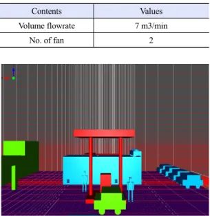
Table 2. Installation specifications of ventilation fan
Contents Values
Volume flowrate 7 m3/min
No. of fan 2
Fig. 1. Grid generation for module packaged hydrogen refuel- ing system
려움을 극복하고자 하고 있다 .
패키지형 수소충전 모델은 수소 압축, 저장, 충전 설비를 콤팩트하게 하나의 패키지 형태로 구성하여 수소자동차에 압축수소를 충전한다 . 일본의 경우 전체의 약 30% 정도가 패키지형 수소충전소로 구 축되어 운영되고 있으며 국내에서도 도입을 적극 추진하고 있다. 이러한 패키지 수소충전시스템은 필요면적을 줄이고 기존 시설에 복합 형태로 수소 충전소를 구성할 때 효과적 방법으로 평가받으며 설치시간을 단축하는 장점을 가지고 있는 반면, 누 출 위험요소들이 밀집한 공간에 배치됨으로써 누출 로 인한 사고 발생시 다른 설비에 영향을 미칠 수 있어 위험요인을 내포하고 있다. 따라서 본 연구에 서는 패키지형 수소충전시스템의 위험요인을 분석 하고 위험을 최소화할 수 있는 방안을 모색하고자 하였다. 상용으로 개발된 3D 위험성 평가 해석 프 로그램을 이용하여 패키지 충전시스템 내부에서 발 생할 수 있는 최악의 사고 시나리오를 구성하여 시 뮬레이션을 수행하고 위험 경감 방안에 대한 효과 를 확인하였다.
2. 수치 해석 모델
본 연구는 패키지형 수소충전시스템의 환기 및 화재·폭발 해석을 위하여 3차원 CFD 해석 툴인 FLACS를 활용하였다. 전산유체역학(CFD)은 편미분 방정식을 수치 해석하여 유체의 유동 현상을 연구, 폭발과정을 예상하는 모델이다
2). FLACS는 화재·폭 발 해석 분야에서 실증과 검증을 통하여 상당한 신 뢰성을 보이는 것으로 알려져 있으며
2,3), 수소분야의 해석에 있어 많은 연구자들에 의해 좋은 분석 결과 를 나타내는 해석 도구로 이용되고 있다
4-6). FLACS 는 3차원 유동장 해석을 위해 Navier-Stokes 방정식 을 수치모델하고 , 난류해석을 위해 k-ε모델을 적용한 다
7,8).
3. 수치 해석 조건
3.1 모듈시스템 모델링
FLACS를 활용한 환기 및 화재·폭발 해석을 위해 Tables 1, 2와 같이 NFPA 2 (>0.3048 Nm
3/min/m
2)와 KGS코드(>0.5 Nm
3/min/m
2)에서 규정하고 있는 실 내 수소설비 환기 조건을 충족하도록 (환기 능력:
0.5879 Nm
3/min/m
2) 수소충전 패키지를 설계하였다.
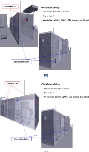
Figs. 1, 2 및 Tables 3, 4에서 패키지형 수소충전시스
템에 대한 수치해석 모델 및 격자생성 방법을 표시
하였다. 두 대의 모델은 공통적으로 측면 상부에 2곳
의 강제환기팬과 측면 하부 2곳의 자연환기구를 가
지며, 측면 상부 1곳 혹은 천정부 1곳의 자연환기구
를 가지도록 하여 환기구 위치에 따라 누출가스의
Table 3. Grid table of ceiling natural ventilation model
Contents (X) (Y) (Z)
No. of control vol. 68 61 57
Min. control vol sizes 0.09 0.08 0.08 Max. control vol sizes 4.71 2.59 3.59
Total no. of cells 236,436
Table 4. Grid table of side natural ventilation model
Contents (X) (Y) (Z)
No. of control vol. 63 61 57
Min. control vol sizes 0.09 0.08 0.08 Max. control vol sizes 4.71 2.59 3.59
Total no. of cells 219,051 (a)
(b)
Fig. 2. Geometry and boundary conditions for module pack- aged hydrogen refueling system. (a) Top side natural ven- tilation, (b) ceiling natural ventilation
잔량이 어떤 차이를 보이는지 알고자 한다 .
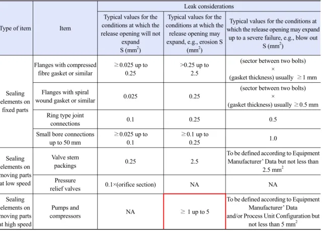
3.2 시뮬레이션 조건시뮬레이션 조건을 선정하기 위해 누출원의 크기 와 누출시간에 대해 아래와 같이 기존의 문헌들을 참고하였다 . 누출원의 크기는 IEC 60079-10-1
9)(KS IEC 60079-10-1
10), KGS GC101
11))에서 권장하는 2차 누출등급에서 누출원의 크기를 참조하였다 (Table 5).
모듈패키지의 경우 고속구동부품류 (압축기)를 포함 하고 있어 누출원의 크기를 1-5 mm
2로, 이 중에서 가장 최악 (worst)의 경우를 가정하여 5 mm
2를 누출 원 크기로 결정하였다 . 누출 지속시간은 모듈패키지 내 수소가스검지기가 설치되므로 , 실험
12)결과를 참 조하였다(Table 6). 실험을 통해 5종류(S1-S4: cata- lytic combustion, range 0-100%, S5: electrochemical, range 0-50,000 ppm)의 응답시간(response time, t
50[s])을 고려, 4초 및 15초로 설정하였다. 폭발 해석을 위한 점화시간 (ignition time)은 가스확산 해석(Run No. 710010~710021) 결과로부터 패키지 내부의 가 스 운 (gas cloud, Q9) 크기에 따라 5단계로 구분하여 점화시간을 설정하였다 . 여기에서 Q9(가중 등가 화 학량론 부피, weighted equivalent stoichiometric vol- ume)는 등가 연소속도와 팽창비율의 영향으로 체적 을 가중시켜 가스농도의 영향을 설명하는 체적측정 법으로 , 다음과 같이 정의된다
13).
Q9 = ∑V×BV×E/(BV×E)stoich (1)
여기에서 V는 가연성 물질 부피, BV는 층류 연소 속도, E는 일정한 공기 압력에서 연소하여 발생하는 부피 팽창량이다 .
4. 수치 해석 결과
4.1 농도장 해석 결과
이상의 시험 조건을 Table 7에서 정리하였으며
Table 5. IEC Recommended leak sizes9)
Type of item Item
Leak considerations Typical values for the
conditions at which the release opening will not
expand S (mm2)
Typical values for the conditions at which the
release opening may expand, e.g., erosion S
(mm2)
Typical values for the conditions at which the release opening may expand
up to a severe failure, e.g., blow out S (mm2)
Sealing elements on
fixed parts
Flanges with compressed fibre gasket or similar
≥0.025 up to 0.25
>0.25 up to 2.5
(sector between two bolts)
×
(gasket thickness) usually ≥1 mm Flanges with spiral
wound gasket or similar 0.025 0.25
(sector between two bolts)
×
(gasket thickness) usually ≥0.5 mm Ring type joint
connections 0.1 0.25 0.5
Small bore connections up to 50 mm
≥0.025 up to 0.1
≥0.1 up to
0.25 1.0
Sealing elements on moving parts at low speed
Valve stem
packings 0.25 2.5
To be defined according to Equipment Manufacturer’ Data but not less than
2.5 mm2 Pressure
relief valves 0.1×(orifice section) NA NA
Sealing elements on moving parts at high speed
Pumps and
compressors NA ≥ 1 up to 5
To be defined according to Equipment Manufacturer’ Data and/or Process Unit Configuration but
not less than 5 mm2
Table 6. Response time of Gas detections13)
S1 S2 S3 S4 S5
t50 (s) 2.3 3.1 3.3 3.8 15.3
Final reading 49% LFL 48.3% LFL 52% LFL 50% LFL 125 mV
Standard gas test (%LFL) 50 50 50 50 50
Figs. 3-5에서 CFD툴을 활용한 시뮬레이션 결과를 보여주었다 .
환기시간에 따른 모듈패키지 내부의 수소농도 분 포(Fig. 3)에서 천정부에 환기구를 설치한 경우(Run No.710011, 710021) 환기시간이 약 220초를 경과하 면 내부의 수소 농도가 50%LFL (2 vol%H2) 이하로 감소하는 반면 측면 벽 상부에 환기구가 설치된 경 우(Run No.710010, 710020)에는 5분이 경과한 후에 도 내부 수소가스의 농도가 여전히 50%LFL을 상회 하는 결과를 보였다.
Fig. 4의 시간에 따른 모듈패키지 내부 Q9 분포를 통해 총 5구간으로 구분, 점화시간에 따른 폭발 영 향을 평가하였다 (5s/73001, 33s/73002, 88s/73003, 180s/73004, 300s/73005). Run No.710020과 710021 을 비교하였을 때 , 측면 환기구가 있는 경우 약 40초 이후에 천정 환기구보다 큰 Q9(가중 등가 화학량론 부피)를 나타내고 있다.
Fig. 5에서 측면 상부 1곳에 자연환기구를 설치한
경우(Fig. 5[a], Run No.710020) 가스누출 이후 5분
경과 후에도 잔존하는 수소가스를 확인할 수 있으며 ,
Fig. 4. Q9 profiles versus ventilation time
Fig. 3. Hydrogen concentration distribution versus ventilation time
(a)
(b)
Fig. 5. Gas dispersion of leaked gas in the module packaged Hydrogen refueling system. (a) Top side natural ventilation (Run No.710020), (b) ceiling natural ventilation (Run No.710021) Table 7. Simulation conditions for module packaged Hydrogen refueling system
Run No.
Leak conditions Ventilation conditions Ignition conditions Leak area
(mm2)
Leak duration (s)
Fan volume flow rate (m3/min)
Natural outlet vent
Ignition time (s)
Ignition position
710010 5.0 4 14.00 Upper side - -
710011 5.0 4 14.00 Ceiling - -
710020 5.0 15 14.00 Upper side - -
710021 5.0 15 14.00 Ceiling - -
730021 5.0 15 14.00 Ceiling 5.1 (9.5, 0.5, 2.9)
730022 5.0 15 14.00 Ceiling 33.1 (9.5, 0.5, 2.9)
730023 5.0 15 14.00 Ceiling 88.1 (9.5, 0.5, 2.9)
730024 5.0 15 14.00 Ceiling 180.1 (9.5, 0.5, 2.9)
730025 5.0 15 14.00 Ceiling 300.1 (9.5, 0.5, 2.9)
820021 5.0 15 14.00 Ceiling 1.1 All monitor region
Table 8. Effect of radiant heat16) Intensity
(kW/m2) Effect
4.0 Feel pain and skin will swell up unless not protected within 20 seconds 12.5 Enough energy to induce ignition of wood or
plastic tubes
37.5 Device and equipment are damaged (a)
(b)
Fig. 6. Jet-fire and heat flux distribution by leaked hydrogen gas. (a) Jet-fire distribution (Run No.820021), (b) heat flux distribution (Run No.820021)
Fig. 7. Overpressure by explosion of module packaged Hydrogen refueling system
천정부에 자연환기구를 설치한 경우 (Fig. 5[b], Run No.710021) 수소가스의 모듈패키지 내 완전 배출을 확인할 수 있다.
4.2 제트화염 해석 결과
모듈패키지 내부의 수소가스 누출시 즉시 점화에 따른(Run No.820021) 제트화염이 발생할 경우
14)패 키지 내부 전체에 형성된 화염을 확인할 수 있다 (Fig. 6). 또한 제트화염 발생시 배관 및 설비 표면에 화염에 의한 고온의 복사열 형성이 확인된다 . Table 8 에 따르면 37.5 kW/m
2이상의 지속적인 복사열 노출 은 배관 및 설비의 파손의 의한 가스누출 및 폭발로 인한 2차 피해 발생 가능성을 나타낸다. 그러므로 패
키지 내부 화재 발생시 즉시 화염을 감지하고 시스 템을 안전하게 차단할 수 있도록 KGS FP217에서 규 정하고 있는 화염감지 및 차단시스템 적용
15)이 적절 함을 확인하였다 .
4.3 폭발 해석 결과
Fig. 4의 결과에 따라 모듈패키지 내 Q9의 크기별
5단계 각각의 폭발 영향 분석을 실시한 결과를 Fig. 7
에 나타내었다 . 내부 누적가스의 폭발로 인해 모듈패
키지 내부의 압력이 상승하게 되어 Run No.730021
의 경우 폭발과압이 10.5797 bar, 730022의 경우
5.3998 bar, 730023의 경우 3.1334 bar, 730024의 경
우 0.5017 bar, 730025의 경우 0.0016 bar로 각각 예
측되었다 . Table 9에 따르면 0.03 bar부터 의미 있는
피해를 보이며 0.6 bar 이상에서 패키지 시스템이 상
당한 피해를 받게 된다.
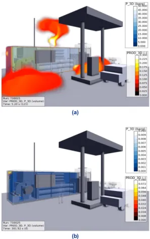
(a)
(b)
Fig. 8. Explosion results of module packaged Hydrogen refu- eling system. (a) Gas explosion (Run No.730021, Ignition af- ter 0.10 s), (b) gas explosion (Run No.730025, Ignition after 1.32 s)
Table 9. Impact of explosion overpressure16)
Pressure (bar) Impact
0.03-0.07 All windows are broken 0.21 Steel structure of the building is damaged
0.48 Trucks are overturned
0.62 Lorries are overturned 0.69 Damage to most buildings and heavy
equipments
Figs. 7, 8에서 점화 시간에 따른 가스폭발 시뮬레 이션 결과를 확인할 수 있다 . 점화 시간이 5분일 때 폭발과압이 0.0016 bar이므로, 5분 동안 환기시스템 이 정상 작동할 경우 누출가스에 의한 폭발피해 방지 가 가능하다 . 따라서 충전소의 긴급차단(emergency shut down) 상황에서도 환기장치는 지속 작동하여야 한 다.
환기가 충분이 이루어지지 못한 상황에서 폭발이 발생할 경우 높은 폭발과압과 화염이 충전기 방향으 로 형성되므로, 모듈패키지 시스템과 충전설비 사이 에는 방호벽 설치를 통해 피해확산을 방지하는 조치 (KGS FP217)가 필요함을 확인하였다.
5. 결 론
본 연구는 밀폐구조의 수소 압축 /저장 패키지 시 스템의 안전성 향상을 위해 3차원 CFD 해석 프로그 램(FLACS)을 활용하여 개선방안을 도출하고 위험 저감 효과를 확인하였다.
패키지 충전시스템의 위험요인인 패키지 내부의 대량 가스누출을 모사하기 위하여 최악의 누출 조건 (IEC60079010-1)을 적용하였고, 환기구의 위치에 따 른 환기 성능과 내부 화재 및 폭발에 따른 피해영향 을 검토하였다. 연구 결과를 요약하면 다음과 같다.
1) 환기구의 위치에 대한 영향 평가에서는 측면 상부에 환기구 설치시 천정부에 수소가스가 잔류하 는 현상이 발생하였고 , 천정부에 환기구를 설치할 경 우 잔류가스 없이 안전하게 환기되는 것을 확인하였 다.
2) 패키지 내부에서 제트화염 발생시 주변 설비에 상당한 피해를 미칠 수 있으며 , 이를 방지하기 위한 화염검지기 및 가스차단장치의 필요성을 확인하였 다.
3) KGS 코드에 따른 강제 환기장치와 천정부의 자연환기구에 의해 적절한 환기가 이루어질 경우 5분 이내에 위험 상황이 해소될 수 있음을 확인하였다 .
4) 완벽한 환기가 이루어지기 이전 상황에서 패키
지 내부에서 폭발이 발생할 경우 폭발압력 및 화염
이 충전설비에 영향을 미칠 수 있어 패키지 시스템
과 충전설비 사이에 방호벽을 설치하도록 하고 있는
현행 기준이 적절함을 확인하였다 .
후 기
본 연구는 산업통상자원부 (MOTIE)와 한국에너지 기술평가원(KETEP)의 지원을 받아 수행한 “패키지 형 수소충전소 플랫폼 모델 개발 및 실증 ” 연구 과제 이다(No.20163010041780).
References
1. J. Park, Y. Huh, and S. KANG, “A Study on Site to Build Hydrogen Multi Energy Filling Station in Domestic LPG Station”, Trans. of the Korean Hydrogen and New Energy Society, Vol. 28, No. 6, 2017, pp. 642-648, doi:
https://doi.org/10.7316/KHNES.2017.28.6.642.
2. P. Middha, O. R. Hansen, and I. E. Storvik, “Validation of CFD model for hydrogen dispersion”, J. of Loss Prevention in the Process Industries, Vol. 22, No. 6, 2009, pp.
1034-1038, doi: https://doi.org/10.1016/j.jlp.2009.07.020.
3. O. R. Hansen, J. Renoult, M. P. Sherman, and S. R. Tieszen,
“Validation of FLACS-hydrogen CFD consequence prediction model against large scale H2 explosion experiments in the FLAME facility”, 2005. Retrieved from https://www.
gexcon.com/us/image/ICHS_Pisa_Hansen_2005.pdf.
4. J. H. Baek, H. J. Lee, and C. B. Jang, “Comparison of H2, LNG and LPG explosion characteristics in a limited space using CFD Simulation”, Journal of the Korean Institute of Gas, Vol. 20, No. 3, 2016, pp. 12-21, doi:
https://doi.org/10.7842/kigas.2016.20.3.12.
5. S. K. Kang, H. J. Bang, and Y. D. Jo, “Consequence Analysis of Hydrogen Blended Natural Gas using 3D CFD Simulation”, Journal of the Korean Institute of Gas, Vol. 17, No. 5, 2013, pp. 15-21, doi: https://doi.org/10.7842/kigas.2013.17.5.15.
6. S. K. Dan, K. J. Park, T. O. Kim, and D. Shin, “Explosion Simulations for the Quantitative Risk Analysis of New Energy Filling Stations”, Journal of the Korean Institute of Gas, Vol. 15, No. 1, 2011, pp. 60-67, doi: https://doi.org/10.7842/
kigas.2011.15.1.060.
7. “FLACS User’s Manual”, GexCon AS, Norway, 2015.
Retrieved from https://www.gexcon.com.
8. D. Y. Pyo and O. T. Lim, “A Study on Explosive Hazardous Areas in Hydrogen Handling Facility”, Trans. of the Korean Hydrogen and New Energy Society, Vol. 30, No. 1, 2019, pp.
29-34, doi: https://doi.org/10.7316/KHNES.2019.30.1.29.
9. IEC 60079-10-1, “Classification of areas - Explosive gas at- mospheres”, International Electrotechnical Commission, 2015.
10. KS C IEC 60079-10-1, “Classification of areas - Explosive gas atmospheres”, Korean Standards Service Network, 2017.
11. KGS GC101, “Classification Code for Explosive Hazardous Area on Gas Facility”, Korea Gas Safety Corporation, 2018.
Retrieved from https://cyber.kgs.or.kr/codesrc/kgscode_
pdf/2018/GC101_180712.pdf.
12. T. Hübert, U. Banach, S. Bouchet, P. Castello, and P. Moretto,
“Safety of Hydrogen as an Energy Carrier – Deliverable D54, Sub-task IP1.2 Gas detection experiments”, HySafe, 2007. Retrieved from https://cordis.europa.eu/docs/
publications/1236/123655741-6_en.pdf.
13. P. Middha and O. R. Hansen, “CFD Simulation Study t o Investigate the Risk from Hydrogen Vehicles in Tunnel s”, International Journal of Hydrogen Energy, Vol. 34, No.
14, 2009, pp. 5875-5886, doi: https://doi.org/10.1016/j.ijhyd
ene.2009.02.004.
14. J. S. Ko and H. Kim, “The Fire Risk Assessment in Compressed Natural Gas Buses & Gas Station”, T. of Korean Institute of Fire Sci. & Eng., Vol. 18, No. 2, 2004, pp. 57-67. Retrieved from http://www.koreascience.or.kr/article/JAKO2004119
22360764.page.
15. KGS FP217, “Facility/Technical/Inspection Code for Vehicles Refueling by Type of Compressed Hydrogen Delivery”, Korea Gas Safety Corporation, 2019. Retrieved from https://cyber.
kgs.or.kr/codesrc/kgscode_pdf/2019/FP217_190614.PDF.
16. Kosha Guide P-102-2013, “Technical guide on accident damage prediction techniques”, Korea Occupational Safety and Health Agency, 2013. Retrieved from http://www.kosha.or.kr/