http://dx.doi.org/10.14316/pmp.2013.24.4.205
Part of this paper has been presented at the 12th Seoul Radiation Oncology Symposium, at Seoul National University, Seoul, Korea, September 13, 2013.
Submitted December 12, 2013, Accepted December 17, 2013 Corresponding Author: Byong Yong Yi, Department of Radiation On- cology, University of Maryland School of Medicine, 22 S Greene Street Baltimore, MD, 21201, USA
Tel: 1-410-328-7165, Fax: 1-410-328-2618 E-mail: [email protected]
Practical Considerations in Preparing an Institutional Procedure of Image Guided Radiation Therapy
Byong Yong Yi
Department of Radiation Oncology, University of Maryland School of Medicine, Baltimore, MD, USA Recent developments of image guided radiation therapy (IGRT), especially the On Board Imaging (OBI) system and the cone beam CT (CBCT), enable the radiation treatment more accurate and reliable. IGRT is widely used in the radiation therapy as a standard of care. Use of IGRT is even expected to increase in the near future.
IGRT is only beneficial to patients when it is used with proper considerations of safety and appropriateness of the techniques. Institutional procedure should be developed based on the clinical need and the deep understanding of the system before applying the new technique to the clinic. Comprehensive QA program should be established before to the clinic and imaging dose should be considered when preparing the departmental practice guidelines for IGRT.
Key Words: IGRT, QA, Institutional procedure
INTRODUCTION
Accurate delivery of radiation, in terms of both geometry and dosimetry, is the one of the most important tasks to ach- ieve successful treatments. Image Guided Radiation Therapy or IGRT has been an important modality for accurate and precise radiation treatment.
1)The concept of image guidance in radia- tion therapy is not new, if we define it as to use of images to determine the target when delineating the targets and deliver- ing the treatments. Historically, use of images starts from the beginning of radiation therapy. Same orthovoltage X-ray was used for both imaging and treatment, in the beginning fol- lowed by gamma and linac grams to determine the beam directions. Many IGRT technologies have been used in the ra- diation therapy field since then. Recent years, new in-room technologies have provided the opportunity for unprecedented
accuracy in radiation therapy delivery. The concomitant ex- panding use of intensity-modulated RT (IMRT) and hypo- fractionated stereotactic techniques has required improved ac- curacy, providing a strong impetus to adopt IGRT.
2)Since mega-voltage imaging technology had been developed, notably electronic portal imaging devices (EPID),
3)in room mounted
4)or gantry mounted kV-imaging systems have been introduced.
5)Recent developments enable the acquisition of volumetric im- ages from MV
6,7)or from kV images.
8-11)Ultra sound
12-14)and optic systems
15)are also introduced to confirm patients’ setup.
Greco et al.
16)defined the definition of IGRT in a broader and more appropriate context. It includes (1) detection and di- agnosis, (2) delineation of target and organs at risk, (3) deter- mining biological attributes, (4) dose distribution design, (5) dose delivery assurance and (6) deciphering treatment response through imaging. That is, the 6 D’s of IGRT. They pointed out that target definition, biological attribute determination, and deciphering treatments response are the most challenging as- pects of IGRT and strategies to advance these areas are need- ed for the benefits of IGRT to be brought to full fruition.
IGRT is one of the major research topics in radiation oncol-
ogy field. Statistics on the topics of scientific presentations of
the 2013 annual conference of the American Association of
Physicists in Medicine or AAPM may represent the research
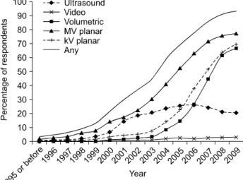
Fig. 1. Use of IGRT in USA. Redrawn from Fig. 5 of reference 2.
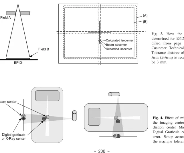
Fig. 2. Typical setup of prostate using CBCT.
trends of this field. Total 650 oral presentations (65 sessions) for this year are presented. Those of the past two years are not much different: 587 oral presentations (64 sessions) for 2012 and 593 presentations (56 sessions) for 2011. More than a quarter of the sessions (26%, 17 sessions) are on the topics of the image guided radiation therapy for this year. It was 22% (14 sessions) and 18% (10 sessions) for 2012 and 2011, respectively. And also 4D issues such as motion management, 4D imaging and 4D dose evaluation are significantly increasing. Number of sessions on the 4D issues is 9 (14%) sessions while it was 5 sessions (8%), last year.
IGRT also is the modality of the standard of care in radia- tion therapy. For example, AAPM Task Group Report 101 states on the SBRT
17)as follows: “For SBRT, image-guided localization techniques shall be used to guarantee the spatial accuracy of the delivered dose distribution with a high con- fidence level.” Simpson
2)recently conducted a nation-wide sur- vey of the use of IGRT in the radiation oncology community in 2009. It is studied how many radiation oncologists currently use these technologies, which technologies are used and to what extent, and how they are being applied. The study sur- veyed randomly selected 1600 of approximately 5000 radiation oncologists who were listed in the 2008 American Society for Radiation Oncology (ASTRO) directory. The proportion of 93.5% of the Radiation oncologists are using IGRT. It was 82.3% when the use of megavoltage (MV) portal imaging was excluded from the definition of IGRT. Overall, 59.1% of IGRT users planned to increase use, and 71.4% of nonusers planned to adopt IGRT in the future. According to the report, the per- centages using ultrasound, video, MV-planar, kilovoltage (kV)- planar, and volumetric technologies are 22.3%, 3.2%, 62.7%,
57.7%, and 58.8%, respectively. Ultrasound and MV-planar- based systems were adopted earliest. The percentage of re- spondents adopting ultrasound peaked in 2006, then declined.
The majority of respondents who were using MV-planar tech- nologies (53.4%) reported having implemented them by 2004.
The adoption of kV-planar-based modalities followed, and the majority of users (54.3%) had adopted them by 2006. Volume- tric-based imaging modalities were implemented more recently, and the majority of users (67.1%) had adopted them by 2007.
Trend of adopting the kV-planar and Volumetric based is in- creasing sharply (Fig. 1).
However, importance of use of new technologies appropri-
ately is often overlooked. Unless otherwise stated, in this ar-
ticle, IGRT means an imaging technique using either an On
Board Imaging (OBI) system or a Cone Beam CT (CBCT)
system, since the OBI and the CBCT are very commonly used
in the clinic (Fig. 2).
1,2,8)This review is to emphasize the importance of proper use of IGRT, to list the items to be prepared in order to develop a departmental guideline for IGRT and to introduce references which suggest details of methods.
CLINICAL APPLICATIONS
Planar X-ray images from an OBI system are useful in pa- tient setup, especially when matching with bony anatomy or with implanted fiducial markers. CBCT is capable not only to perform bony matching but also soft tissue matching. Evalua- tion of the delivered dose distribution is also feasible with CBCT (Fig. 2). It even makes possible to alter treatment fields adaptively during the course of treatments. The treatment of most anatomic sites, such as brain, head and neck, breast, esophagus, liver, prostate, lung, rectum and bladder, directly or indirectly benefit from this technique.
9-11,18,19)Because of these benefits, IGRT is changing practice of radiotherapy signifi- cantly and is slowly becoming standard of care. For example, IGRT is necessary for all SBRT.
17)Yi et al.
20)analyzed the setup difference between the orthog- onal portal imaging and X-ray image using 654 orthogonal sets of daily kV image and weekly MV images of 28 patients;
18 pelvic cases, 5 head and neck cases, and 5 abdominal cases.
An anterior and lateral orthogonal set of images are acquired daily for 3 to 39 fractions (median 25 fractions). The 2D-2D matching based on the bony land marks was used to verify the set up. Overall position change from the skin mark was 3.2 mm, 3.6 mm, 2.9 mm (lateral, anterior-posterior, and inferior- superior direction, respectively). Head & neck (2.5, 3.7, 2.5) and Pelvis (3.0, 3.0, 2.7) case showed similar results, while chest and abdominal (4.6, 4.9, 4.2) cases showed larger. The isocenter difference between the MV imager (EPID system) and the kV imager is less than 1.5 mm. The change of iso- center of both of the OBI and the MV imager for different gantry angles were less than 1 mm. Occasions requiring posi- tion shift from the weekly portal image after the position set up with kV images were very rare. From these finding they concluded that weekly MV portal imaging is not necessary when kV images are used for daily set up purpose since daily setup errors are decreased from 5.6 mm to 1 mm with OBI with regard to bony anatomic land marks and expected im-
provement from additional change of the position from another set of MV images is negligible. Systemic error (SE) is calcu- lated by averaging the difference between the skin marker and the kV images for the first 5 fractions. Random error is calcu- lated as the daily variations between the average and the daily setup. Random error can be reduced to less than 3mm for the most of the cases when akin makers are remarked after 5 fractions. This study was performed after commissioning the new OBI system and indirectly tests the usefulness and the validity of the new technique.
Boda-Heggemann et al.
11)reviewed the clinical applications of CBCT systems with emphasis on the most frequently tar- geted body sites (prostate, lung, head and neck). It is reported that IGRT with soft tissue detection improves set-up accuracy and is currently replacing 2D verification and frame-based ster- eotactic treatments; safety margins are significantly reduced by this IGRT technology. In addition, systematic changes of tu- mor volume and shape and of the normal tissue can be moni- tored allowing for adaptation of radiotherapy. IGRT in combi- nation with conformal treatment planning allows for hypo-frac- tionated dose escalation, which results in improved rates of lo- cal tumor control with low rates of toxicity.
It is evident that a margin reduction and the dose escalation is possible when IGRT. Amount of margin reduction, however, should be determined based on the understanding of the ma- chine limitations and the nature of the patients. For an exam- ple, effect of breathing can be detected from the IGRT, but may not be reduced.
CONSIDERATIONS
Image guidance is only safe and appropriate when using properly. Since significant reduction of the margin is often considered, use of IGRT can be even dangerous if not used properly. The importance of ‘safety and appropriateness’ in IGRT is often overlooked, however. QA, proper image inter- pretation and radiation dose are significant aspects of IGRT.
What we see in the images may not necessarily be what we get, unless IGRT is used properly in the clinic.
1. QA of geometry
The accuracy of IGRT relies on the geometrical coincidence
Fig. 4. Effect of misalignment of the imaging center and the ra- diation center Misalignment of Digital Graticule can lead setup error. Setup accuracy relies on the machine tolerance.
Fig. 3. How the isocenter is determined for EPID system (Mo- dified from page 3 of Varian Customer Technical Bulletine).
23)Tolerance distance of Varian Exact Arm (E-Arm) is recommended to be 3 mm.
between the isocenter of the linac and that of the OBI and/or the CBCT.
21,22)If this coincidence is not confirmed routinely, treatment accuracy cannot be guaranteed. Patient setup limi- tations and associated patient setup margins of a given in- stitution should be determined considering that institution’s li- nac and OBI tolerances. AAPM TG-179 recommends a daily QA coincidence tolerance of 2 mm.
1)Geometrical accuracy be- comes even more critical for SBRT. Figs. 3 and 4 show a principle of determining the isocenter of the system. Geometri- cal uncertainty or difference between the isocenter of imaging device and that of the treatment machine directly propagates to the patient setup uncertainty (Recommended tolerance distance of the Varian E-arm is 3 mm
23)). This parameter should be considered when margin reduction. Patient specific geometrical check is frequently overlooked. Coordinate coincidence be- tween the planning system and the record and verifying system (R&V system) should be checked for each beam and each imaging field. Either isocenter coordinates or DICOM coor-
dinates can be checked. It is desirable to check DICOM coor- dinates, since the definition of isocenter can be different be- tween the planning system and the R&V systems. Part of pa- tient body is often truncated in the CBCT due to geometrical limitation of the maximum field of view of the CBCT. It will create error when CBCT is used to determine the SSD or to calculate the delivered dose.
2. Interpretation of the soft tissue
One of the advantages of CBCT is the capability of soft tis- sue matching. However, pixel values of CBCT are not same as those of planning CT (fan beam CT, FBCT) for same patient.
Unlike FBCT, pixel values of the same tissue may be different
depending upon the surrounding materials. Fig. 6 shows cup-
ping and streaking artifacts due to beam hardening and the
streaking. Both cases are the evidence of affected CT numbers
from surrounding tissues. Special care is needed when de-
termining tissue borders for soft tissue matching.
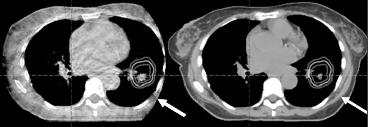
8,11)It is also
Fig. 5. Truncation of CBCT contour (left).
Fig. 7. Different image size of moving target. Free breathing planning CT (a) and. CBCT (b). Size of the target in CBCT is larger, due to volume averaging effect during scanning.
Fig. 6. Artifacts of CBCT images
from surrounding materials: (A
and B) cupping and streaks due
to hardening and scatter. Re-
printed from Figure III-B-1 of re-
ference 4. This figure is recited
from Fig. 7, 8, p. 274, The Modern
Technology of Radiation Oncology,
Volume 2, J. Van Dyk (Ed.) Me-
dical Physics Publishing.
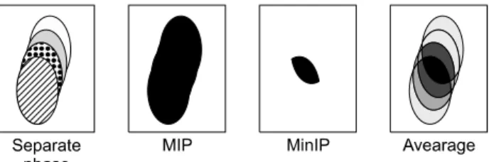
Fig. 8. Different intensity projection protocols of mobile target.
Redrawn from Fig. 1 of reference 24.
important to understand the different effect between the plan- ning CT and the CBCT if the organ is moving. As it is seen in Fig. 7, the size of the organ of the CBCT (Fig. 7b) is larg- er than that of the free breathing planning CT, since the CBCT shows the volume averaging effect. Since both of the artifacts and the volume averaging effects, it is difficult to de- termine setup accuracy with soft tissue. Adjustment of imaging window and level becomes subjective. Two methods are avail- able in determining target boarder of volume averaged imaging of moving organs: (1) average CT and (2) maximum intensity projection (MIP).
24)Fig. 8 shows the principle of the MIP and average. Muirhead showed that MIP image does not match to the union of the 10 phases of 4D CT.
25)Park and his col- leagues even further showed this tendency is dependent to the patient’s breathing cycle.
26)It is also reported that the Internal Target Volume or ITV of the free breathing CBCT is smaller than that from the planning CT when patient breathing pattern is not sinusoidal.
27)3. Imaging dose
The extra dose resulting from imaging is often ignored in the clinic. A dose of 5 (3∼6) cGy per fraction can be ex- pected for each CBCT. This is about 3% of the conventional dose fraction. Daily CBCT for the treatment of 33 fractions will result extra dose of around 1.8 Gy to entire CBCT scan- ning volumes, including the PTV and the normal organs.
28,29)Even higher dose is expected if repeated CTs are acquired.
What is worse is that volume of the imaging dose entire vol- ume, unlike the treatment fields. Wen et al.
28)reported interest- ing asymmetric dosimetry for pelvis. Right hip receives 6∼7 cGy while left hip 10∼11 cGy per CBCT. This asymmetry is due to (1) the kV source always starts from left lateral and ends at left lateral. Gantry rotation gets much slower near the
end but dose rate stays constant; and (2) 10 degree scan over- laps on the left lateral side (start and end). These studies used Varian CBCT. Varian’s CBCT uses a total of 1,320 mAs (660 projections, 2 mAs per projection, 125 kV) while the Synergy system use the total 660 mAs (330 projections) used in at 120 kV. Varian CBCT delivers double the dose to the Elekta.
Also, the lateral dose asymmetry was not reported for the Synergy system.
30)Different machine has different characte- ristics. Frequency of the imaging should be determined based on the clinical need and the machine characteristics.
No consensus has been published whether the imaging dose should be included to the treated dose.
4. Use of CBCT for dose calculation
Use of CBCT for adaptive replanning is a well-known inter- esting concept, which seems to be useful in the clinic. The technique is not yet routinely available for clinical use since the technique is not mature enough. Calculated dose is not re- liable unless the CT numbers of the CBCT images represent the electron density or the mass density, accurately and repr- oducibly. As it is shown in the Fig. 6, inaccurate CT number is technical bottle neck. CT number is not reliable due to arti- facts and severe scattering from the cone beam. Also the trun- cation issue (Fig. 5) is one of the problem sources. Truncation issue only applies to the large patients. Recent papers on tack- ling the CT number issue suggest that it will be very near fu- ture to use CBCT for the adaptive planning using dose evalua- tion. For examples, use of look-up table between the planning CT and the CBCT, Correction of scatter of CBCT and image registration from planning CT.
31,32)Another example is the ef- fort on reducing the scatter components using anti-scatter grid.
33)5. Necessity of institutional procedures
None of the IGRT system is perfect. Understanding the lim-
itation of the system is important. It is also important to share
the information among all of the staffs in the department: phy-
sicians, therapists, dosimetrists and physicists. Geometrical un-
certainty of the IGRT should be reflected in the procedure of
the margin; Use of soft tissue especially when with moving
target should be practiced uniformly in the department; Fre-
quency of the imaging should be applied reasonably.
CONCLUSIONS
IGRT is a useful and powerful tool in radiotherapy only with the proper consideration of safety and appropriateness. A comprehensive QA program of the entire IGRT system is es- sential. The institution’s set up margin needs to be determined considering the institution’s machine tolerances. Variation of pixel number may alter the morphology of the soft tissue in CBCT. Imaging dose is not negligible, and the effect of the additional dose should be considered when determining fre- quency of imaging. It is desirable to practice under the de- partmental IGRT procedures.
REFERENCES
1. Bissonnette JP, Balter PA, Dong L, et al: Quality assur- ance for image-guided radiation therapy utilizing CT-based technologies: A report of the AAPM TG-179. Med Phys 39(4):1946-1963 (2012)
2. Simpson DR, Lawson JL, Nath SK, et al: A survey of im- age-guided radiaton therapy use in United States. Cancer 116 (16):3953-3960 (2010)
3. Lam KS, Partowmah M, Lam WC: An on-line electronic portal imaging system for external beam radiotherapy. Br J Radiol 59:1007-1013 (1986)
4. Adler JR Jr, Murphy MJ, Chang SD, Hancock SL:
Image-guided robotic radiosurgery. Neurosurgery 44(6):1299- 1306 (1999)
5. Sorcini B, Tilikidis A. Clinical application of image-guided radiotherapy (IGRT) on the Varian OBI platform. Cancer Radiother 10(5):252-257 (2006)
6. Mosleh-Shirazi MA, Evans PM, Swindell W, Webb S, Partridge M: A cone-beam megavoltage CT scanner for treatment verification in conformal radiotherapy. Radiother Oncol 48(3):319-328 (1998)
7. Pouliot J, Bani-Hashemi A, Chen J, et al: Low-dose mega- voltage cone-beam CT for radiation therapy. Int J Radiat Oncol Biol Phys 61(2):552-560 (2005)
8. Yin FF, Wong J, Balter J, et al: The Role of In-room kV x-ray Imaging for Patient Setup and Target Localization: Report of AAPM Task Group 104, in AAPM Report, American Associa- tion of Physicists in Medicine, College Park, MD (2009).
9. Guckenberger M, Meyer J, Wilbet J, et al: Cone-beam CT based image-guidance for extracranial stereotactic radio- therapy of intrapulmonary tumors. Acta Oncologica 45(7):897- 906 (2009)
10. Li H, Zhu XR, Zhang L, et al: Comparison of 2D radio- graphic images and 3D cone beam computed tomography for positioning head-and-neck radiaotherapy patients. Int J Radiat Oncol Biol Phys 71(3):916-925 (2008)
11. Boda-Heggemann J, Lohr F, Wenz F, Flentje M, Guc- kenberger M: kV Cone-Beam CT-based IGRT: A clinical Review. Strahlentherapie und Onkologie 187(5):284-291 (2011) 12. Morr J, DiPetrillo T, Tsai JS, Engler M, Wazer DE:
Implementation and utility of a daily ultrasound-based local- ization system with intensity-modulated radiotherapy for prostate cancer. Int J Radiat Oncol Biol Phys 53(5):1124-1129 (2002) 13. Chandra A, Dong L, Huang E, et al: Experience of ultra-
sound-based daily prostate localization. Int J Radiat Oncol Biol Phys 56(2):436-447 (2003)
14. Langen KM, Pouliot J, Anezinos C, et al: Evaluation of ultrasound-based prostate localization for image-guided radio- therapy. Int J Radiat Oncol Biol Phys 57(3):635-644 (2003) 15. Park YK, Son T, Kim H, et al: Development of real-time
motion verification system using in-room optical images for res- piratory-gated radiotherapy. JACMP 14(5):25-42 (2013) 16. Greco C, Ling CC: Broadening the scope of Image-Guided
Radiotherapy (IGRT). Acta Oncologica 47(7):1193-1120 (2008) 17. Benedict SH, Yenice KM, Followill D, et al: Stereotactic body radiation therapy: The report of AAPM Task Group 101.
Med Phys 37(8):4078-4101 (2010)
18. Lamba M, Breneman JC, Warnick RE: Evaluation of im- age-guided positioning for frameless intracranial radiosurgery.
Int J Radiat Oncol Biol Phys 74(3):913-919 (2009)
19. Lerma F, Liu B, Yi B, Amin P, Yu C: Role of image-guided patient repositioning and online planning in localized prostate cancer IMRT. Radiotherapy and Oncology 93(1):18-24 (2009) 20. Yi B, Lerma F, Suntharalingam M: Is weekly megavoltage
image verification necessary after daily kv image guidance? Int J Radiat Oncol Biol Phys 72(1):S571-S572 (2008)
21. Yoo S, Kim GY, Hammoud R, et al: A quality assurance program for the on-board imagers. Med Phys 33(11):4431-4447 (2006)
22. Klein EE, Hanley J, Bayouth J, et al: Task group 142 re- port: Quality assurance of medical accelerators. Med Phys 36(9):4197-4212 (2009)
23. Varian Customer Technical Bulletin, CTB-PV-457a, May 11, 2006.
24. Underberg RWM, Lagerwaald FJ, Slotman BJ, Cuijpers JP, Senan S: Use of maximum intensity projections (MIP) for target volume generation in 4DCT scans for lung cancer. Int J Radiat Oncol Biol Phys 63(1):253-260 (2005)
25. Muirhead R, McNee SG, Featherstone C, Muscat S:
Use of maximum intensity projections (MIPs) for target outlining in 4DCT radiotherapy planning. J Thorac Oncol 3(12):1433–1438 (2008)
26. Park KW, Huang L, Gagne H, Papiez L: Do maximum in- tensity projection images truly capture tumor motion? Int J Radiat Oncol Biol Phys 73(2):618-625 (2009)
27. Vergalasova I, Maurer J, Yin FF: Potential underestimation of the internal target volume (ITV) from free-breathing CBCT.
Med Phys 38(8):4689-4699 (2011)
28. Wen N, Guan H, Hammond R, et al: Dose delivered from Varian’s CBCT to patients receiving IMRT for prostate cancer.
Phys Med Biol 52(8):2267-2276 (2007)
방사선 치료용 영상 장치 지침서 작성을 위한 실용적인 고려사항