for Marine Environmental Engineering
Vol. 13, No. 1. pp. 12-17, February 201012
OWC형 파력발전 공기실의 파랑집중장치의 효과에 대한 수치적인 연구
류 진1·현범수2,†·홍기용3·김길원2
1중국해양대학교 산동성중점해양공학실험실
2한국해양대학교 조선해양시스템공학부
3한국해양연구원 해양시스템안전연구소
Effects of Wave Focusing Device on Performance of OWC Chamber
Zhen Liu1, Beom-soo Hyun2,†, Keyyong Hong3 and Ji-yuan Jin2
1Shandong Province Key Laboratory of Ocean Engineering, Ocean University of China, Qingdao 266-100, China
2College of Ocean Science and Technology, Korea Maritime University, Busan 606-791, Korea
3Maritime and Ocean Engineering Research Institute, KORDI, Daejeon 305-343, Korea
요 약
OWC 파력발전장치는 에너지 변환장치로 널리 사용되고 있고 공기실의 작동성능을 향상시키기 위하여 파랑집중장
치를 고안 하였다. 본 논문에서 사용된 수치조파수조는 two-phase VOF모델을 기반으로 하여 구현되었고 재생된 규칙 입 사파는 공기실까지 전달되어 내부의 왕복 유동장을 형성하게 하였다. 수치조파수조는 연속방정식, Reynolds-averaged Navier-Stokes 방정식, two-phase VOF 법으로 구성 되였고 standard k- 난류모델, 유한체적법, NITA-PISO 알고리즘 그리고 dynamic mesh기능을 채택하였다. OWC 공기실 파랑집중장치의 성능에 대하여 수치적으로 고찰하였다.
Abstract − Oscillating Water Column (OWC) device has been widely employed in the wave energy conversion.
Wave Focusing Device (WFD) is proposed to be helpful for improving the operating performance of OWC cham- ber. In the present paper, a Numerical Wave Tank (NWT) using two-phase VOF model is utilized to simulate the generation and propagation of incident regular waves, water column oscillation inside the chamber. The NWT con- sists of the continuity equation, Reynolds-averaged Navier-Stokes equations and two-phase VOF functions. The standard k- turbulence model, the finite volume method, NITA-PISO algorithm and dynamic mesh technique are employed.
Effects of WFD on the operating performance of OWC chamber are investigated numerically.
Keywords: Wave energy conversion(파력발전변환장치), Oscillating water column(진동수주), Wave Focusing Device(파랑집중장치), Numerical wave tank(수치조파수조)
1. INTRODUCTION
Wave energy is one of the most promising forms of ocean renewable sources because of its high energy density. Oscillat- ing Water Column (OWC) devices have been widely employed in the wave energy conversion. It comprises a partially sub- merged air chamber with an opening in the front skirt, and the water column exposes to the incident wave field through the underwater opening. The air turbine linked to the electric gen- erator is installed in the air duct.
A number of efforts have been made to study the perfor- mance of OWC air chamber. Evans [1982] first developed the analyzing theory of OWC wave energy absorption. Physical model with different bottom slopes was constructed and tested in a wave tank under regular wave conditions by Wang et al. [2002].
Liang et al. [2003] studied the air chamber performance under incident wave heights and nozzle ratios experimentally. Hong et al. [2007] performed an experiment concentrating on the effects of several shape parameters of OWC chamber in wave energy absorbing capability. You [1993] presented a boundary element method to study the influence of coastal topography and the harbor shape on the oscillations of the OWC plant. Jos-
†
Corresponding author: [email protected]
This paper was selected and reviewed for publication from EAWOMEN2009.
VOF model based on the commercial CFD code Fluent V 6.2.16 is utilized to simulate the generation and propagation of incident regular waves, air pressure and air flow rate variation in the chamber-duct system, which have been validated by the corresponding experimental data. Effects of wave focusing device on the operating performance of OWC chamber are investi- gated numerically.
2. NUMERICAL WAVE TANK
The 3D regular incident waves are generated by the piston motion of the wave making plate at one end of the flume. In this study, the fluids are incompressible and immiscible. At the interface of two fluids, no phase change and no-slip between fluids are assumed. The interface tracking between air and water phases is accomplished by the Volume of Fluid (VOF) method (Hirt and Nichols, [1981]).
The continuity equations, Reynolds Averaged Navier-Stokes (RANS) equations and volume fraction equations are employed in the numerical model. The standard k- model, which is widely used in engineering application, is required to close the above system of equations and applied to describe the turbulence phe- nomenon in the water and air dynamic motions.
In addition, the face fluxes through the computational cells are obtained as the geometric reconstruction approach. The interface between two fluids is calculated by the piecewise-linear scheme (Youngs, [1982]), which assumes the linear slope in each cell.
On the opening boundary, the Sommerfeld radiation bound- ary condition (Sommerfeld, [1949]) is used to obtain the rela- tion between the horizontal velocity component and the free surface elevation. The wave absorption can be performed by controlling the motion of the opening boundary within the velocities opposite to the water particles adjacent to the open- ing boundary on the x-direction.
In Fluent, the symmetry definition is applied for the wave making and absorbing boundaries. The bottom and chamber structures are set as the wall boundaries using the standard wall functions. The pressure outlet boundary is taken account for the top boundaries of the computational domain adjacent to the air phase (free in or outflow of air).
The capability of the numerical wave tank on the simulation of wave elevations, air pressure and air flow variation inside the chamber has been proved by Liu et al. [2008a] and Liu et al. [2008b]. The numerical prediction of the operating perfor- mance of the OWC chamber has shown good agreement with the corresponding experimental data.
3. NUMERICAL ANALYSIS ON WAVE FOCUSING DEVICE
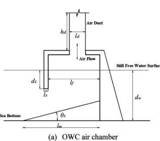
3.1 Wave Focusing Device and OWC chamber The schematic of the OWC air chamber with an cylinder duct installed at the center of the top cover is shown in Fig.
1(a), where lf denotes the chamber width, ds the draft of the chamber skirt, ls the thickness of the chamber skirt, ld the diam- eter of the cylinder duct, hd the length of the duct. The still water depth is dw=16m. The slope angle of bottom θs and the base length of the slope lm are fixed as 26° and 23m, respectively.
The schematic of Wave Focusing Device (WFD) is illustrated in Fig. 1(b). The WFD consists of two symmetrical vertical walls. One side of the vertical walls is connected with one cor- ner of the front skirt of OWC air chamber, and the other end extends to the sea. The two vertical walls show bell-mouthed shape to the incident wave direction. When the incident waves arrive at the facility, the water surface will be enhanced during the propagation because of the effects of wave focusing device.
The standing waves appear in front of the chamber and the amplitudes are evidently higher than the case of the chamber
without WFD.
The expending angles of vertical walls shown in Fig. 1(b) are θw. lw denotes the wall length, lb the chamber width and hw
the projected length of the wall in the incident wave direction.
In order to be convenient for the calculation and analysis, the
vertical walls are connected with sea bed in the present paper.
The top heights equal to that of the air chamber.
Thirteen cases with various test conditions are summarized in Table 1. In all the cases, there are no air turbines installed in the duct and effects of the turbine were not induced in this study yet. The incident waves whose period varies from 3.5s to 8.0s are employed for each case. In the numerical simulation, the OWC chamber is settled at the end of the wave tank, which is opposite to the wave maker plate. 8 to 10 regular waves were simulated and employed after the incident waves arrived the front skirt of the chamber. The corresponding shape parame- ters of OWC chamber is as the follows: lf= 6.0 m, ds=3.0 m, ls=1.0 m, hd=10.0 m and ld=2.0 m. The incident wave height is fixed as 2.0 m.
Fig. 1. Schematic of OWC chamber and Wave Focusing Device Table 1. Testing Case in the Numerical Simulation
Case h
w(m) θ
w(°) Case h
w(m) θ
w(°)
01 0 0 08 4.0 45
02 1.0 30 09 8.0 45
03 2.0 30 10 1.0 60
04 4.0 30 11 2.0 60
05 8.0 30 12 4.0 60
06 1.0 45 13 8.0 60
07 2.0 45
Fig. 2. 3D Instantaneous Snapshot of free water surface inside WFD, Case 09, T=5.0s
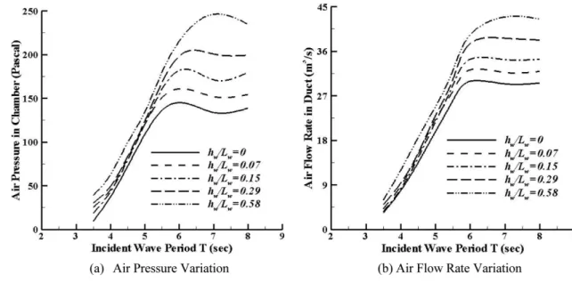
parameter hw/lb is employed in the present paper to demon- strate the effects of length of vertical wall of Wave Focusing
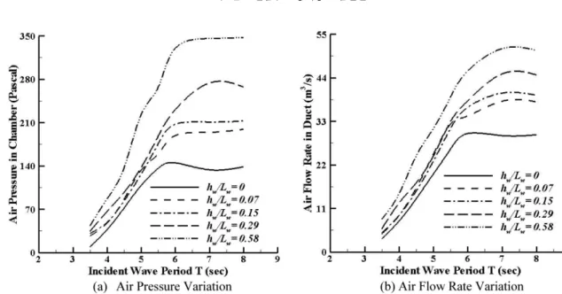
can be observed for expending angles 45° and 60° as shown in Fig. 4-5. The evaluating parameters of OWC air chamber with-
Fig. 3. Effects of WFD wall length on performance of OWC chamber, θ
w=30°.
Fig. 4. Effects of WFD wall length on performance of OWC chamber, θ
w=45°.
out WFD are evidentially smaller than the chamber with WFD. It also can be concluded that the peak value always occurs at the period T=7.0s. In general, the wave energy con- verting efficiency of OWC chamber will increase as the wall lengths increase under the fixed chamber width and expend- ing angles.
The comparison of operating performance of OWC cham- ber within WFD for various expending angles is shown in Fig. 6. The incident wave period investigated here is T=7.0s.
It can be seen that the air pressure and flow rate will increase as the expending angle increases when the length of the WFD is fixed. Furthermore, the WFD with larger expending angles shows better performance than that with smaller angles.
4. CONCLUSIONS
A 3D numerical wave tank based on the commercial CFD software Fluent 6.2.16 using VOF model has been developed to simulate the wave propagation in this paper. The RANS equations, standard turbulence model and dynamic mesh tech- nology were employed in the present model.
The Wave Focusing Devices within bell-mouthed shaped vertical walls are employed to improve the wave energy con- verting efficiency of OWC air chamber. The numerical results indicate that the Wave Focusing Devices has minor effects on the performance of OWC chamber in the short wave period and significant effects on the wave energy absorbing. The oper- ating performance of OWC chamber also will increase as the
Fig. 5. Effects of WFD wall length on performance of OWC chamber, θ
w=60°.
Fig. 6. Effects of WFD expanding angles on performance of OWC chamber, θ
w=45°.
All the support is gratefully acknowledged.
REFERENCES