1. 서 론
Recently, a long-term evolution (LTE) multiple-input multiple- output (MIMO) has been reported to enhance the communication service for transportation such as roadways and railways [1-5]. Furthermore, with the development of wireless communication services requiring broadband characteristics, such as software-defined radio (SDR) and cognitive radio (CR), the demand for broadband antennas has increased.
In order to measure SDR as well as LTE-MIMO, the discone antenna could be utilized for source antenna since the operating frequency band is broad and a 50-Ω feeder cable is connected to the antenna directly [6-7]. Especially,
discone antenna has the omni-directional pattern [8].
A discone antenna was proposed in 1946 [9], which is composed of a disk, cone, and a feeder cable. The disk must be separated from the cone, while a conductive disk is usually thin and flat.
Consequently, the disk is weak, so the disk antenna should be protected by a dielectric material, such as a radome or dielectric cover [10].
In this study, dielectric materials were used to support the disk of a discone antenna, and their effects on the reflection coefficient and gain were examined. The influence of several parameters of the dielectric gap- and side-supports was examined using electromagnetic simulations.
Design and Parametric Study on Discone Antenna for Broadband RF Test Chamber
Soon-Soo Oh*, In-Ryeol Kim*, Dong-Geun Choi**, Wook-Ki Park***
Abstract This paper discusses the characteristics and effects of dielectric inner-supports on discone antenna for broadband RF test chamber, and the verification has been performed by simulation. Several design parameters such as the thickness of the gap support, the position of the side support, and the thickness of the side support has been analyzed. The thickness of the gap support affected the reflection coefficient. An effect of the offset of the side support from the center was slight below 3 GHz and significant above 3 GHz. The thickness of the side support did not affect the reflection coefficient or the gain much. The performance of the fabricated discone antenna was in good agreement with the simulated results. This investigation of a dielectric support effects could be used to design a commercial discone antenna for broadband RF test chamber, focusing on electrical performance and mechanical stability.
Key Words : antenna measurement, dielectric support, discone antenna, RF test chamber
This research was supported by a grant of the 『Research on Evaluation of Radio Frequency through Approach of Electromagnetic Engineering』 fund from RRA (Radio Research Agency) in 2016, and this research was supported by research fund from Chosun University in Korea, 2016.
*Dept. of Electronics Engineering, Chosun University
**National Radio Research Agency
***Corresponding Author : Incheon Economy Industry Information Technopark, Future Industrial Technology Center ([email protected])
Received October 24, 2016 Revised December 12, 2016 Accepted December 26, 2016
2. Antenna Geometry and Simulation
2.1 Antenna Geometry
Figure 1 shows the geometry of a discone antenna with dielectric supports. The cylindrical symmetry is easily imagined, as shown below in a photograph of the fabricated antenna. The antenna is fed with a 50-Ω coaxial-line: its inner conductor is connected to the metallic disk, while its outer conductor is connected to the conductive flared cone. The cone is Hc = 49.8 mm high, and has a bottom diameter of Dc = 51.9 mm and a top diameter of Dg = 5.0 mm.
The disk is Dd = 38.0 mm in diameter and 1.0 mm thick.
Fig. 1. Geometry of a discone antenna with dielectric supports
The disk of a discone antenna should be supported by a dielectric material, such as the gap- and side-supports shown in Fig. 1. The dielectric gap support is placed between the top of the cone and disk. The gap support is Tg = 1.0 mm thick, and its diameter Dg is identical to that of the top of the cone. The dielectric side support is placed around the circumference of the disk at a distance from the center of Rs = 19.5 mm. The side support is cylindrical, with a height of Hc = 39.2 mm and thickness of 1.0
mm. The gap- and side-supports are made of Teflon, which has a permittivity of εr = 2.1 and loss tangent of tanδ = 0.001.
2.2 Simulation Results
As shown in Fig. 1, the gap and size supports are necessary to keep the disk flat.
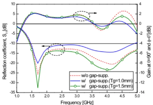
Their effects were investigated by sweeping several parameters. First, the influence of a dielectric gap support was simulated using ANSYS HFSS [11]. The reflection coefficient (S11) and gain at θ = 90° and φ = 0° are shown in Fig. 2. Here, no side support was included in the simulation. The reflection coefficient described in this paper is the ratio of the reflected wave to the incident wave [7-8].
The gain is the multiplication of directivity and efficiency, in which the directivity is how much directive compared to the isotropic pattern [7-8].
The performance of S11 and the gain decreased with a gap support, although the performance was restored when the gap support thickness was increased from Tg = 1.0 to 1.5 mm.
1.0 1.5 2.0 2.5 3.0 3.5 4.0 4.5 5.0
-35 -30 -25 -20 -15 -10 -5 0 5 10
-14 -12 -10 -8 -6 -4 -2 0 2 4
R e fle ct io n c o e ff ic ie n t, S
11[d B ]
Frequency [GHz]
w/o gap-supp.
w/ gap-supp.(Tg=1.0mm) w/ gap-supp.(Tg=1.5mm)
G a in a t q= 9 0
oa n d f =0
o[d B i]
Fig. 2. Reflection coefficient and gain with or without a gap support
Second, the influence of the dielectric side support was examined. The reflection coefficient
(S11) and gain at θ = 90° and φ = 0° are shown in Fig. 3. The simulated model did not include a gap support. With a side support, the performance of S11 and the gain was similar until 3.0 GHz; above 3.0 GHz, it depended on Rs. Interestingly, the gain at 4.0 GHz was about –10 and 0 dBi for Rs = 10 and 19 mm, respectively, so there could be an optimum value. In this paper, Rs was set at 19 mm since the disk was well protected when Rs = Dd/2.
Third, the effect of the thickness of the side support, Ts, was investigated. Three models with different Ts were simulated. The gap support was not included in these simulation models. As Fig. 4 shows, the S11 curve was below –10 dB from 1.5 GHz, while the gain curves differed slightly around 3.5 GHz.
1.0 1.5 2.0 2.5 3.0 3.5 4.0 4.5 5.0
-35 -30 -25 -20 -15 -10 -5 0 5 10
-14 -12 -10 -8 -6 -4 -2 0 2 4
R e fle ct io n c o e ff ic ie n t, S
11[d B ]
Frequency [GHz]
w/o side-supp.
w/ side-supp.(Rs = 3mm) 10mm 19mm
G a in a t q= 9 0
oa n d f =0
o[d B i]
Fig. 3. Reflection coefficient and gain with or without a side support
1.0 1.5 2.0 2.5 3.0 3.5 4.0 4.5 5.0
-35 -30 -25 -20 -15 -10 -5 0 5 10
-14 -12 -10 -8 -6 -4 -2 0 2 4
Reflection coefficient, S11[dB]
Frequency [GHz]
w/ side-supp.(Ts = 0.5mm) 1.0mm 1.5mm
Gain at q=90o and f=0o[dBi]
Fig. 4. Reflection coefficient and gain versus the thickness of the side support
3. Fabricated Results
A discone antenna with gap- and side-supports of the optimum geometry was fabricated and tested. Figure 5 shows the fabricated antenna without and with a side-support. Here, a gap support was inserted to maintain the gap of the fabricated antenna.
(a) (b)
Fig. 5. Photograph of fabricated discone antenna (a) with and (b) without a side-support
1.0 1.5 2.0 2.5 3.0 3.5 4.0 4.5 5.0
-25 -20 -15 -10 -5 0
measured (w/o side-supp.) (w/ side-supp.)
R e fle ct io n c o e ff ic ie n t, S
11[d B ]
Frequency [GHz]
Fig. 6. Measured reflection coefficient with or without a side-support of optimized discone antenna
1.5 2.0 2.5 3.0 3.5 4.0 4.5 5.0
-8 -6 -4 -2 0 2 4
measured (w/o side-supp.) (w/ side-supp.) G a in a t q= 9 0
oa n d f =0
o[d B i]
Frequency [GHz]
Fig. 7. Measured gain with or without a side-support
of optimized discone antenna
Fig. 6 shows the measured reflection coefficient. The measured reflection coefficients with side-support showed the similar results without side-support until about 3.0 GHz; above 3.0 GHz, they differed.
Figure 7 shows the measured gains, both with and without a side support. Here, the gain was achieved at θ = 90° and φ = 0°. The two sets of results showed good agreement. As discussed above, the gain was similar below 3 GHz, but differed above 3 GHz.
4. Conclusion
In this paper, the effects of a dielectric gap- and side-supports on a discone antenna were investigated. These showed that the thickness of the gap support affected the reflection coefficient S11. An offset of the side support from the center also affected S11 and the gain; the effect was slight below 3 GHz and significant above 3 GHz. The thickness of the side support did not affect S11 or the gain much. The results measured with the fabricated antenna were similar to the simulation results. Therefore, dielectric gap-and side-supports can be used to support and protect the disks of discone antennas used in LTE MIMO chamber.
REFERENCES
[1] Lei L., Lu J., Jiang Y., Shen X. S., Li Y., Zhong Z., and Lin C.(2016), “Stochastic Delay Analysis for Train Control Services in Next-Generation High-Speed Railway Communications System,”
IEEE Transactions on Intelligent Transportation Systems
, vol. 17, no. 1, pp.48-64.
[2] Song, J. W., Kim B. H., Jeong R. G., and
Kwak K. S.(2012), “Spatial Coding using Data Information and Antenna Selection Technique in MIMO System,”
The Journal of The Korea Institute of Intelligent Transport Systems
, vol. 11, no. 6, pp. 81-88.[3] Ahn S. K., Jeong G. T., Lee H. C. and Kwak K. S.(2014), “A 4-port MIMO Antenna for LTE Femtocell using Cross Decoupler,”
The Journal of The Korea Institute of Intelligent Transport Systems
, vol. 13, no. 2, pp. 50-56.[4] Vogt-Ardatjew R., van de Beek S., and Leferink F.(2012), “Wide-band antennas for reverberation chambers,”
in International Symposium on Electromagnetic Compatibility
, Pittsburg, USA.[5] Raimundo X., Salous S., and Nasr K.(2012), “ UWB MIMO measurements in reverberation chamber and indoor environment,”
in Proc. Int. Symp.
Signals, Systems, and Electronics
, Potsdam, Germany.[6] Volakis J.(2007),
Antenna Engineering Handbook
, McGraw-Hill, pp. 408-416.[7] Stutzman W. L. and Thiele G. A.(1998),
Antenna Theory and Design
, John Wiley& Sons, pp. 243-245.
[8] Kraus J. D. and Marhefka R. J. (2002),
Antennas for all Applications
, McGraw-Hill, p. 638.[9] Kandoian A. G.(1946), "Three new antenna types and their applications,“
Proc. IRE
, vol. 34, pp. 70W-75W.[10] Persson K., Gustafsson M., Kristensson G., and Widenberg B.(2014), “Radome diagnostics- Source reconstruction of phase objects with an equivalent currents
approach,”
IEEE Trans. on Antennas and Propagation
, vol. 62, no. 4, 2041-2051.[11] High-Frequency Structure Simulator (HFSS), ANSYS.
Author Biography
Soon-Soo Oh
• Aug. 2003: Korea Univeristy, Microwave and Optic Eng., Ph. D.
• Sep. 2003 ~ Apr. 2005:
University of Manitoba, Post-Doc, Fellow
• May 2005 ~ Aug. 2013 : ETRI Senior Researcher
• from Sep. 2013: Chosun University, Electronics Eng., Assistant Professor
• from Sep. 2013: IEEE Senior Member
<Research Interest>
Array antenna analysis and Design, Electromagnetic field measurement, Microwave filter
In-Ryeol Kim
• Aug. 2014: Chosun University, Electroncis Eng., B.S. Degree
• from Sep. 2014: Chosun University, Master Course
<Research Interest>
Array antenna analysis and Design, Radar
Dong-Geun Choi
• Feb. 2003 : Chungbuk University, Information and Comm. Eng., B.S. Degree
• Feb. 2005 : Chungbuk University, Information and Comm. Eng., Master Degree
• Feb. 2016 : Hanyang University, Electrical Eng., Ph. D. Degree
• from Jun. 2006 : Radio Research Agency, Eng.
Officer
<Research Interest>
Wave propagation, SAR evaluation, Electromagnetic Safety, Antenna Design
Wook-Ki Park
![Fig. 3. Reflection coefficient and gain with or without a side support 1.0 1.5 2.0 2.5 3.0 3.5 4.0 4.5 5.0-35-30-25-20-15-10-50510 -14-12-10-8-6-4-2024Reflection coefficient, S11[dB] Frequency [GHz] w/ side-supp.(Ts = 0.5mm)](https://thumb-ap.123doks.com/thumbv2/123dokinfo/5316714.384813/3.892.158.757.368.1011/fig-reflection-coefficient-gain-support-reflection-coefficient-frequency.webp)
