EFFECT OF RESTORATION TYPE ON THE STRESS DISTRIBUTION OF ENDODONTICALLY TREATED MAXILLARY PREMOLARS; THREE-DIMENSIONAL FINITE ELEMENT STUDY
Heun-Sook Jung1, Hyeon-Cheol Kim1, Bock Hur1, Kwang-Hoon Kim2, Kwon Son2, Jeong-Kil Park1*
1Department of Conservative dentistry, School of Dentistry, Pusan National University
2Department of Mechanical design engineering, College of Engineering, Pusan National University
The purpose of this study was to investigate the effects of four restorative materials under various occlusal loading conditions on the stress distribution at the CEJ of buccal, palatal surface and central groove of occlusal surface of endodontically treated maxillary second premolar, using a 3D finte element analysis.
A 3D finite element model of human maxillary second premolar was endodontically treated. After endodontic treatment, access cavity was filled with Amalgam, resin, ceramic or gold of different mechanical properties. A static 500N forces were applied at the buccal (Load-1) and palatal cusp (Load-2) and a static 170N forces were applied at the mesial marginal ridge and palatal cusp simultaneously as centric occlusion (Load-3). Under 3-type Loading condition, the value of tensile stress was analyzed after 4-type restoration at the CEJ of buccal and palatal surface and central groove of occlusal surface
Excessive high tensile stresses were observed along the palatal CEJ in Load-1 case and buccal CEJ in Load-2 in all of the restorations. There was no difference in magnitude of stress in relation to the type of restorations. Heavy tensile stress concentrations were observed around the loading point and along the cen- tral groove of occlusal surface in all of the restorations. There was slight difference in magnitude of stress between different types of restorations. High tensile stress concentrations around the loading points were observed and there was no difference in magnitude of stress between different types of restorations in Load- 3. [J Kor Acad Cons Dent 34(1):8-19, 2009]
Key words: Stress distribution, Finite element analysis, Endodontically treated teeth, Restorative material, Occlusal loading
- Received 2008.10.8., revised 2008.10.27., accepted 2008.10.29-
Ⅰ. Introduction
Restoration of the endodontically treated tooth is a critical final step for successful endodontic therapy.
Many dentists assume that endodontically treated teeth are weakened and more prone to be fractured due to dessication or premature loss of fluids supplied by vital pulps1).
An in vitro study by Panitvisai and Messer2) demonstrated that access preparations result in greater cuspal flexure, increasing the probability of cuspal fracture, because the preparation results in a deep and extended cavity, reducing the amount of dentin to a critical extent3). In general, it was known that the optimal restoration of an endodontically treated posterior tooth should be a cast inlay with cuspal overlays or, if necessary, a full crown. An extracoronal restoration that covers the cusps is the most commonly recommended method for reducing the risk of fracture1,4,5). Other forms of coronal cover- age-including gold, ceramic, or resin composite onlays and cusp-covering silver amalgam restora- ABSTRACT
*Corresponding Author: Jeong-Kil Park Department of Conservative Dentistry
College of Dentistry, Pusan National University 1-10 Ami-dong, Seo-gu, 602-739, Busan, Korea Tel: 051-240-7454
E-mail: [email protected]
tions may also provide endodontic treated teeth with protection against fracture. According to retrospective study6), convincing evidence was reported that 1273 endodontically treated teeth were investigated to identify significant causes of failure and concluded that the presence of cuspal coverage was the only significant restorative variable to predict long-term success.
Hannig et al.1)suggested that endodontic treatment does not cause teeth to become more brittle, and dehydration after endodontic treatment does not weaken the dentinal structure either. A recent study reported that endodontically treated teeth and their contralateral vital pairs exhibited similar biomechan- ical properties, such as punch shear strength, tough- ness, and load required for fracture7).
Reeh et al.3) suggested that endodontic procedures have only a small effect on the tooth, reducing the relative stiffness by 5%. This numerical value was less than that of an occlusal cavity preparation (20%). The largest losses in stiffness were related to the loss of marginal ridge integrity. Mesiooccluso-dis- tal (MOD) cavity preparation resulted in 63% aver- age loss in relative cuspal stiffness, and MOD and endodontic access cavities resulted in 80% loss in cuspal stiffness8). This means that every effort should be made to maintain at least one marginal ridge in the endodontically treated teeth.
When endodontic access can be conservative and proximal tooth structure remains intact, simple restoration of the endodontic access opening may be adequate. It seems as if the bonding ability of restorative systems to cavity walls is more effective on the fracture resistance than other mechanical fea- tures.
In the decreased tooth deflection after restoration with posterior composites and dentinal bonding agents in conservative preparations, tooth movement was similar to that of cusps in the unaltered tooth5).
The ability to predictably restore an endodontically treated tooth to its original strength and the fracture resistance without placement of a full-coverage restoration could provide patients with potential peri- odontal and economic benefits. More recently empha- sis has been placed on intracoronal strengthening of teeth to protect them against fracture9). Dentine
bonded reinforced composites resins and amalgams, adhesive ceramic inlays that provide internal rein- forcement of teeth without occlusal coverage have been advocated1).
Trope et al.4)showed that the resistance to fracture of endodontically treated premolars was significantly increased when the teeth were restored with compos- ite resin placed intracoronally after acid etching.
Recently these findings were confirmed by Reeh et al.5) who found that endodontically treated teeth restored with composite resin after enamel and dentin etching were significantly stronger than those left unrestored and their strength was almost strong same as intact teeth.
Composite resin bonded to enamel and dentine has been found to restore at least part of the stability of the unprepared tooth while exacting less additional preparation8). In terms of fracture resistance, no sig- nificant difference was observed between direct com- posite resin restorations and ceramic inlays10). The frequency of cusp fracture of endodontically treated premolars was investigated in a retrospective study.
After endodontic therapy, the teeth were restored either with a MOD amalgam filling or with enamel bonded MOD resin filling. A very high frequency of cusp fracture was found in premolars restored with amalgam11).
Studies have shown that after endodontic treat- ment, teeth restored with bonded restorations are more resistant to fracture compared with those restored with silver amalgam, but both bonded silver amalgam and bonded cast metal inlays have been advocated for reinforcement of prepared teeth1).
Finite element analysis (FEA) is particularly useful in dentistry since it can readily cope with both the complex geometry of a tooth and its supporting struc- tures along with the large variation in physical prop- erties. FEA studies concerned about MOD restora- tions of endodontically treated maxillary premolars are numerous. But FEA study of conservative bonded access cavity restoration is rare.
The objective of this study was to investigate the effects of four conservative restoration types such as composite resin, amalgam restorations, ceramic and gold inlay restorations on the stress distribution of endodontically treated maxillary second premolar
under various occlusal loading conditions, using 3 dimensional (3D) FEA.
Ⅱ. Materials and Methods 1. Finite element model
To develop a 3D FE model, intact normal extracted human maxillary second premolars were selected in this study. The premolar were scanned serially with Micro-CT (SkyScan 1072; SkyScan, Aartselaar, Belgium) to exposure the tooth sections perpendicu- lar to the long axis of the tooth (58 ㎛ in thickness) and parallel to the occlusal plane. 3D-DOCTOR (Able Software Co., Lexington, MA, USA) image pro- cessing software was employed to detect the bound- aries of enamel, dentin and pulp from the sectioned two dimensional images and to make a three-dimen- sional surface model. Rhino 3D (Robert McNeel &
Assoc., Seattle, WA, USA) was used to reduce use- less nodes from the surface model and ANSYS (Swanson Analysis Systems, Inc., Houston, USA) was used to mesh.
All the vital tissues were presumed linearly elastic, homogeneous and isotropic. The corresponding elastic properties such as Young's modulus and Poisson's ratio were determined according to literature sur- vey12,13)(Table 1).
The periodontal ligament was assumed to be 0.3 mm wide, and the dimensions of surrounding com- pact and cancellous bone were derived from standard texts14,15). The alveolar bone was also generated by growing the outer surface of the tooth model from 2 mm below the CEJ. The pulp region was modeled as being hollow. In these models, the outer surface of
the alveolar bone model was fixed in order to prevent rigid body motion for FEA.
The model was fixed to restrict the mesiodistal movement. In all loading cases, the base nodes of simulated alveolar bone were assumed fixed to pre- vent rigid body motion.
2. Restoration
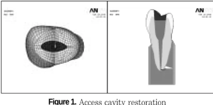
Access cavity was filled with amalgam, composite resin, ceramic, or gold over glass ionomer base (Figure 1). The GIC bases were filled up to ideal cav- ity depth from canal orifice.
The data of material properties such as elastic modulus, Poisson’s ratio used in this study were obtained by literature review12) (Table 2). Z100 (3M Dental Products, St. Paul, MN, USA) was used as representatives of hybrid resin. The interface between materials were set as complete bonding
3. Loading conditions
In order to determine the load conditions such as Table 1.Mechanical properties of the tooth and sup-
porting structure used in the study
Materials Mechanical properties Young's modulus (MPa) Poisson's ratio(υ)
Enamel 84000a 0.33a
Dentin 18000a 0.31a
PDL 0.667b 0.49b
Cancellous bone 13700b 0.38b
Cortical bone 34000b 0.26b
a: Katona TR and Winkler MM.12) b: Geramy A and Sharafoddin F.13)
Figure 1.Access cavity restoration
(light brown; GI base, dark brown: restorative material).
Table 2. Mechanical properties of the materials used in the study
Materials Mechanical properties Young’s modulus (GPa) Poisson’s ratio(υ)
Amalgam 50a 0.24a
Z 100 15.2b 0.28b
Ceramic 69a 0.25a
Gold 93c 0.39c
Glass ionomer 10.8d 0.3d
a: Couegnat et al.16), b: Katona et al.12), c: Suansuwan et al.17), d: Ichim et al.18)
magnitudes, directions, occlusal contacts (i.e., point or surface, centric or eccentric), preliminary investi- gation was performed using the data gathered by lit- erature review19). Based upon these data, 170 N was assumed as the chewing force for premolars and 500 N was assumed as the heavy parafunctional load of bruxism and traumatic occlusion.
A Static force was applied for the following loading conditions (Figure 2). The eccentric heavy occlusion was simulated with two loading conditions. Load-1 represented the perpendicular load of 500 N at the restored surface of upper third of palatal incline of buccal cusp. Load-2 represented the perpendicular load at the restored surface of upper third of buccal incline of palatal cusp. And physiologic centric occlu- sion was simulated with Load-3. Load-3 represented a unit load distributed at the two points correspond- ing to centric occlusion (perpendicular load of 100 N on the upper third of buccal slope of palatal cusp and perpendicular load of 70 N on the center of mesial marginal ridge).
4. Maximum principal stress analysis
The maximum principal stresses of each restoration under Load-1, 2 and 3 were evaluated. The values of maximum principal stress along the CEJ of the buc- cal and palatal surface and central groove of occlusal surface were analyzed.
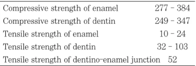
The data of ultimate strength of enamel and dentin
are cited from the report of Litonjua et al.20)(Table 3).
Ⅲ. Results 1. Load-1
1) Buccal CEJ (1)Stress patterns
The difference of stress pattern was not observed along the CEJ of all of the four types of restorations (Figure 3).
(2) Maximum principal stress analysis
Stress of 5.3 MPa was shown at the mesial point area (Node 2) and an even higher tensile stress of 7.4 MPa was shown at the distal point area (Node 8), but compressive stress also manifested in the rest of the areas. There were no differences in magnitude of stresses among the four types of restorations (Figure 4).
Figure 2.Three load conditions of 3D FE model.
Load-1: loading at A point (500 N) Load-2: loading at B point (500 N)
Load-3: simultaneous loading at B point (100 N) and C point (70 N)
Table 3.Mechanical properties of teeth (MPa) Compressive strength of enamel 277 - 384 Compressive strength of dentin 249 - 347 Tensile strength of enamel 10 - 24 Tensile strength of dentin 32 - 103 Tensile strength of dentino-enamel junction 52
Figure 3. The buccal view of maximum principal stress distribution under Load-1.
Amalgam Ceramic
Gold Composite resin
2) Palatal CEJ (1) Stress patterns
Maximum principal stress was distributed along the CEJ and the highest tensile stress was concen- trated at the area a little to the distal from the mid- palatal. There were no differences in the pattern of stress distributions among the four types of restora- tions (Figure 5).
(2) Maximum principal stress analysis
Overall, high tensile stress of over 50 MPa resulted along the CEJ with no difference in magnitude of stresses among the four types of restorations. The tensile stress of mesial point area (Node 9) was 55.3 MPa and a peak tensile stress of 144.1 MPa was exhibited at the point little to the distal from the
mid-palatal (Node 4) while tensile stress at the dis- tal point area (Node 1) registered 73.4 MPa (Figure 6).
3) Occlusal Central groove (1) Stress patterns
The maximum principal stress was concentrated around the buccal loading point and along the central groove of occlusal surface in a different way among the four types of restorations (Figure 7).
(2) Maximum principal stress analysis
There were differences in stress value among the four types of restorations along the central groove.
Figure 4.The maximum principal stress distribution along the buccal CEJ under Load-1.
Figure 5. The palatal view of maximum principal stress distribution under Load-1.
Amalgam Ceramic
Gold Composite resin
Figure 7.Different stress patterns of occlusal surface under Load-1.
Amalgam Ceramic
Gold Composite resin
Figure 6.The maximum principal stress of CEJ of palatal surface under Load-1.
Load-1 Buccal
Amalgam Ceramic Gold Resin
Mesial Mid-Buccal Distal
MPa Load-1 Palatal
Amalgam Ceramic Gold Resin
Distal Mid-Palatal Mesial
MPa
High tensile stress was concentrated at the mesial (Node 2) and distal (Node 6) marginal ridges. Peak tensile stress of 57.3 MPa was detected at the distal marginal ridge (Node 6) in the case of composite resin restoration and magnitude of stress value was followed by amalgam, ceramic and cast gold restora- tion (Figure 8).
2. Load-2
1) Buccal CEJ (1) Stress pattern
Maximum principal stress was distributed along the CEJ and the highest tensile stress was concen- trated at the area a little to the mesial from the mid- buccal. There were no differences in the pattern of stress distributions among the four types of restora- tions (Figure 9).
(2) Maximum principal stress analysis
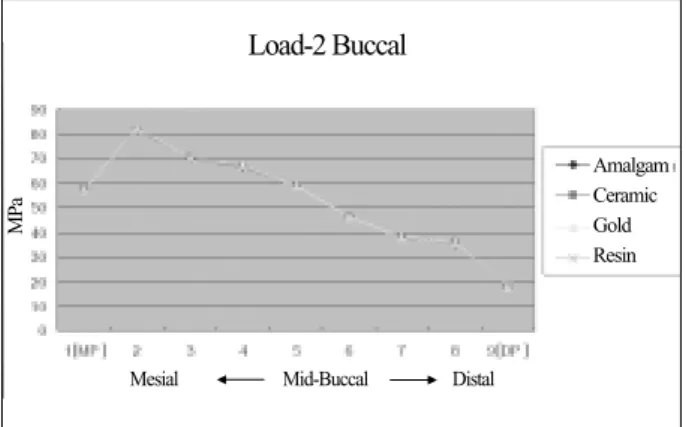
There were no difference in magnitude of stress among the four types of restorations and tensile stress at the mesial point area (Node 1) registered 56.6 MPa. The highest tensile stress of 80.8 MPa was concentrated at mesiobuccal area (Node 2) and stress value was decreased to the distal point area.
The lowest tensile stress of 18.1 MPa was concen- trated at distal point area (Node 9) (figure 10).
.
2) Palatal CEJ (1) Stress pattern
Maximum principal stress distribution was not detected along the CEJ and there was no difference in the pattern of stress distribution among the four types of restorations (Figure 11).
(2) Maximum principal stress analysis
The weak compressive stress was observed along the palatal CEJ except for distal point area (Figure 12).
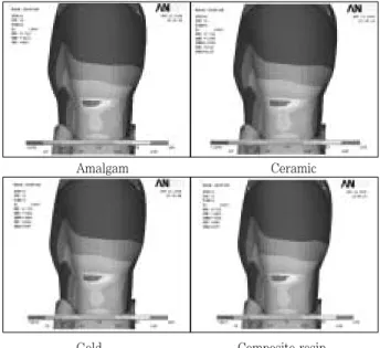
Figure 9. The buccal view of maximum principal stress distribution under Load-2.
Amalgam Ceramic
Gold Composite resin
Figure 8. The maximum principal stress distribution along the central groove of occlusal surface under Load-1.
Figure 10.The maximum principal stress distribution along the CEJ of buccal surface under Load-2.
Load-1 Occlusal
Amalgam Ceramic Gold Resin
Mesial Mid-Occlusal Distal
MPa
Load-2 Buccal
Amalgam Ceramic Gold Resin
Mesial Mid-Buccal Distal
MPa
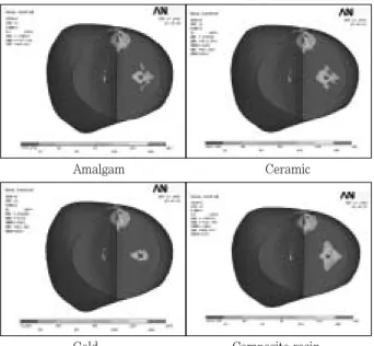
3) Occlusal (1)Stress pattern
There were differences in the patterns of stress dis- tribution around the loading point and along the cen- tral groove among the four types of restorations.
There was no stress distribution on the composite resin restoration (Figure 13).
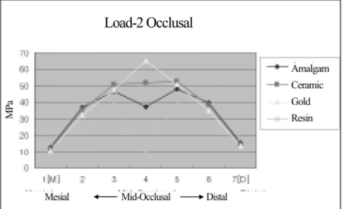
(2) Maximum principal stress analysis
There were differences in stress value among the four types of restorations along the central groove.
High tensile stress was concentrated at the mesial (Node 2) and distal (Node 6) marginal ridges. Peak tensile stress of 44.0 MPa was detected at the distal marginal ridge (Node 6) in the case of composite
resin restoration and magnitude of stress value was followed by amalgam, ceramic and cast gold restora- tion (Figure 14).
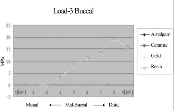
3. Load-3 1) Buccal CEJ (1) Stress pattern
Maximum principal stress did not appear except at distal CEJ and there was no difference among the four types of restorations (Figure 15).
(2) Maximum principal stress analysis
Peak tensile stress (19.1 MPa) was concentrated at the distal point area (Node 8) and there was no differ- ence among the four types of restorations (Figure 16).
Figure 11.The palatal view of maximum principal stress distribution under Load-2.
Amalgam Ceramic
Gold Composite resin
Figure 12.The maximum principal stress distribution along the palatal CEJ under Load-2.
Figure 13. The occlusal view of maximum principal stress distribution under Load-2.
Amalgam Ceramic
Gold Composite resin
Figure 14. The maximum principal stress analysis stress distribution along central groove of occlusal groove under Load-2.
Load-2 Palatal
Amalgam Ceramic Gold Resin
Mesial Mid-Palatal Distal
MPa
Load-2 Occlusal
Amalgam Ceramic Gold Resin
Mesial Mid-Occlusal Distal
MPa
2) Palatal CEJ
(1) Maximum principal stress pattern
There was no difference in stress pattern among the four types of restorations (Figure 17).
(2) Maximum principal stress analysis
Peak tensile stress (4.0 MPa) was observed at the distal point area, however the overall magnitude of tensile stress was smaller than the buccal CEJ.
Compressive stress was observed at both the mid- palatal and mesial areas (Figure 18).
3) Occlusal (1) Stress pattern
Similar stress pattern were present at the loading point C, but there were differences in the pattern around the loading point B among the four types of restorations (Figure 19).
(2) Maximum principal stress analysis
Peak tensile stress (171.9 MPa) was observed around the mesial loading point and there was no difference among the four types of restorations (Figure 20).
Figure 15. The Buccal view of maximum principal stress distribution under Load-3.
Amalgam Ceramic
Gold Composite resin
Figure 16.The maximum principal stress distribution along the Buccal CEJ under Load-3.
Figure 17. The palatal view of maximum principal stress distribution under Load-3,
Amalgam Ceramic
Gold Composite resin
Figure 18.The maximum principal stress distribution along the palatal CEJ under Load-3.
Load-3 Buccal
Amalgam Ceramic Gold Resin
Mesial Mid-Buccal Distal
MPa
Load-3 Palatal
Amalgam Ceramic Gold Resin
Distal Mid-Palatal Mesial
MPa
Ⅳ. Discussion
In sound posterior teeth, buccal and lingual cusps are interconnected by the occlusal enamel and the marginal ridges. As these stabilizing elements are removed during cavity preparation, the cusps are more easily deformed and forced apart during occlusal loading and become more susceptible to cusp or crown fracture8,11,21).
Since dentinal hardness and moisture content in the pulpless teeth are similar to those in the vital teeth1,22), the susceptibility to fracture is believed to be increased due to the cumulative loss of tooth structure during restorative and endodontic proce- dures5), not the effect of endodontic treatment itself.
Hardness measurements of endodontic treated tooth that were treated up to 10 years previously indicated no difference in hardness between endodon- tically treated and vital teeth3). Similiarly, punch shear testing on endodontically treated teeth showed only a small (although statistically significant) reduction in strength of 14%. This suggests that the total effect of endodontic procedures is not great and is in fact comparable to an occlusal cavity prepara-
tion3,22). Lewinstein and Grajower22) in their study of
16 vital and 32 root-filled teeth which had been extracted, indicated that root canal therapy did not affect vickers hardness of dentine, even after periods of 5-10 years.
Endodontic access cavity, and to a greater extent a MOD cavity, can increase this tendency to deflection under mechanical forces. Repeated stresses can greatly reduce the resistance to fracture, causing the tooth to be broken even if the force is far below the loading force required to break a healthy tooth21). Marginal ridges should be preserved and conservative cavity designs and access to the root canals for endodontic treatment will decrease the frequency of fracture in tooth or restoration5).
Ideal final restoration for an endodontically treated tooth should be restored to a certain level of the orig- inal tooth stiffness, so as to decrease the mechanical fatigue of the residual cusps. It should also restore its function and esthetics, protect the remaining tooth structure, and resist marginal microleakage.
The objective of this study was to investigate the possibility of success of bonded intracoronal restora- tion of four restorative materials by the tensile stress analysis of endodontically treated maxillary second premolar under various occlusal loading conditions using a 3D FEA. In this study, conservative endodontic access cavities were simulated with the standard contours (i.e. oval for upper premolars) with sound marginal ridge.
Stress analysis was focused at the CEJ area of buc- cal and palatal surface based on the reports of many FEA studies12,23-25). Kuroe et al.26) also confirmed by the photoelastic method that a vertical force loaded on the tooth causes stress concentration at the cervi- cal line. Nothing but the tensile stress was observed in this study, because enamel and dentin are less Figure 19.The occlusal view of maximum principal stress
distribution under Load-3.
Amalgam Ceramic
Gold Composite resin
Figure 20.The maximum principal stress distribution along the central groove of occlusal surface under Load-3.
Load-3 Occlusal
Amalgam Ceramic Gold Resin
Mesial Mid-Occlusal Distal
MPa
resistant to tensile stress than compressive stress.
In tensile stress analysis of the CEJ of buccal and palatal surface, high stress distribution over the fail- ure range was observed at the midpalatal CEJ under Load-1 and mesiobuccal CEJ under Load-2 in all of the restorations. The peak tensile stress of 144.1 MPa was concentrated at the Node 4 a little to the distal from the mid-palatal under Load-1. The high- est tensile stress of mesiobuccal CEJ under Load-2 was 80.8 MPa. Tensile stress of palatal CEJ under Load-1 was higher than tensile stress of buccal CEJ under Load-2. These results revealed a strong asso- ciation between loading forces of Load-1 and the pos- sibility of failure of enamel and dentin of the mid- palatal cervical area by tensile stress.
In the occlusal surface, the tensile stress at the marginal ridges under Load-1 was slightly higher than under Load-2. All of the stress values at the CEJ and marginal ridge were over the limit of mechanical properties of the tooth. Therefore, the Load-1 is considered as the major factor to jeopardize the restoration durability and palatal cusp fracture than Load-2. In these instances of eccentric heavy occlusion, vertical fracture may occur along central groove because tensile stress was shown in the mar- ginal ridge. Milicich et al.27) suggested that vertical fracturing in the contact point area of the peripheral rim can occur when cusps are placed under tension loads.
Trope et al.4) concluded that when loaded to frac- ture, teeth restored with amalgam or with a cavity preparation alone tended to fracture from the base of the cavity preparation to the cervical area. In the result of another study28) the fractures of lingual cusps occurred in the 55 teeth out of 60.
The fact that lingual cusp fractures occur more often than buccal cusp fractures may be ascribed to tooth weakening during cavity preparations because of the inclination of the tooth and/ or the location of the central fossa, which is usually closer to the lin- gual wall. Lingual cusp fractures ended more fre- quently above or at the gingival crest in teeth with vital pulps, and in non-vital teeth, fractures ended more frequently below the crest.
It has also been reported that in vivo fractures of palatal cusps of maxillary premolars occur more fre-
quently than fractures of those of the buccal cusps29). The frequency of cuspal fracture and its relationship to tooth anatomy has been investigated by Khera et al.30) Their results showed that the functional cusps were significantly wider than the nonfunctional ones, although maxillary premolars had smaller functional cusps.
Because of the special risk of the fracture of palatal cusps of maxillary premolars revealed by the results of this study, full cuspal coverage was recommended and partial-veneer ceramic crowns covering the palatal but not the buccal cusp also recommended as an alternative approach. This type of restoration would also offer esthetic advantages compared with partial-veneer crowns with buccal-cusp1).
In comparison to the Load-1 and Load-2, the stress distribution of the Load-3 showed no difference in magnitude of stress between four types of restora- tions. This result suggests that in physiologic centric occlusion such as Load-3, four types of restoration were restorable without full cuspal coverage. The small size of the cavity preparation and the types of restorations in teeth with small preparations did not appear to produce a concentration of stresses high enough to weaken the teeth significantly.
Ⅴ. Conclusions
Within the limits of this study, following conclu- sions can be drawn:
1. Excessive high tensile stresses were observed along the palatal CEJ in Load 1 case and buccal CEJ in Load 2 case in all of the restorations.
There was no difference in magnitude of stress in relation to the type of restorations.
2. Heavy tensile stress concentrations were observed around the loading point and along the central groove of occlusal surface in all of the restorations. There was slight difference in mag- nitude of stress between different types of restorations.
3. High tensile stress concentrations around the loading points were observed and there was no difference in magnitude of stress between differ- ent types of restorations in Load 3 case.
References
1. Hannig C, Westphal C, Becker K, Attin T. Fracture resistance of endodontically treated maxillary premo- lars restored with CAD/CAM ceramic inlays. J Prosthet Dent 94:342-349, 2005.
2. Panitvisai P, Messer HH. Cuspal deflection in molars in relation to endodontic and restorative procedures. J Endod 21:57-61, 1995.
3. Reeh ES, Messer HH, Douglas WH. Reduction in tooth stiffness as a result of endodontic and restorative pro- cedures. J Endod 15:512-516, 1989.
4. Trope M, Langer I, Maltz D, Tronstad L. Resistance to fracture of restored endodontically treated premolars.
Endod Dent Traumatol 2:35-38. 1986.
5. Reeh ES, Douglas WH, Messer HH. Stiffness of endodontically-treated teeth related to restoration technique. J Dent Res 68:1540-1544, 1989.
6. Sorensen JA, Martinoff JT. Intracoronal reinforcement and coronal coverage: a study of endodontically treated teeth. J Prosthet Dent 51:780-784, 1984.
7. Sedgley CM, Messer HH. Are endodontically treated teeth more brittle? J Endod 18:332-335, 1992.
8. Hofmann N, Just N, Haller B, Hugo B, Klaiber B. The effect of glass ionomer cement or composite resin bases on restoration of cuspal stiffness of endodontically treated premolars in vitro. Clin Oral Investig 2:77-83, 1998.
9. Hernandez R, Bader S, Boston D, Trope M. Resistance to fracture of endodontically treated premolars restored with new generation dentine bonding systems. Int Endod J 27:281-284, 1994.
10. Santos MJ, Bezerra RB. Fracture Resistance of Maxillary Premolars Restored with Direct and Indirect Adhesive Techniques. J Can Dent Assoc 71:585a-585d, 2005.
11. Hansen EK. In vivo cusp fracture of endodontically treated premolars restored with MOD amalgam or MOD resin fillings. Dent Mater 4:169-173, 1998.
12. Katona TR, Winkler MM. Stress analysis of a bulk- filled Class V light-cured composite restoration. J Dent Res 73:1470-1477, 1974.
13. Geramy A, Sharafoddin F. Abfraction: 3D analysis by means of the finite element method. Quintessence Int 34:526-533, 2003.
14. Lindehe J, Karring T. The anatomy of the periodon- tium. In:Schluger S, Yuodelis R, Page RC, Johnson RH, eds. Textbook of Clinical Periodontology, 2nd edi- tion, Munksgaard, Copenhagen, p19-69, 1989.
15. Schroeder HE, Page RC. The normal periodontium. In:
Schluger S, Yuodelis R, Page RC, Johnson RH, des.
Periodontal Diseases, 2nd edition, Lea & Fabiger, Philadelphia, p3-52, 1990.
16. Couegnat G, Fok SL, Cooper JE, Qualtrough AJ.
Structural optimization of dental restorations using the principle of adaptive growth. Dent Mater 22:3-12, 2006.
17. Suansuwan S, Swain M. New approach for evaluating metal-porcelain interfacial bonding. Int J Prosthodont 12:547-552, 1999.
18. Ichim I, Schmidlin PR, Kieser JA, Swain MV.
Mechanical evaluation of cervical glass-ionomer restorations: 3D finite element study. J Dent 35:28- 35, 2007.
19. Widmalm SE, Ericsson SG. Maximal bite force with centric and eccentric load. J Oral Rehabil 9:445-450, 1982.
20. Litonjua LA, Andreana S, Patra AK, Cohen RE. An assessment of stress analyses in the theory of abfrac- tion. Biomed Mater Eng 14:311-321, 2004.
21. Lee HM, Hur B, Kim HC, Woo SG, Kim KH, Son K, Park JK. Effects of occlusal load on the cervical stress distribution : A three-dimensional finite element study. J Kor Acad Cons Dent 31:427-436, 2006.
22. Lewinstein I, Grajower R. Root dentin hardness of endodontically treated teeth. J Endod 7:421-422, 1981.
23. Yettram AL, Wright KW, Pickard HM. Finite element stress analysis of the crowns of normal and restored teeth. J Dent Res 55:1004-1011, 1976.
24. Park JK, Hur B, Kim SK. Stress distribution of class V composite resin restorations: A three-dimensional finite element study. J Kor Acad Cons Dent 33:36-46, 2008..
25. Park JK Hur B Kim SK. The influence of combining composite resins with different elastic modulus on the stress distribution of class V restoration : A three- dimensional finite element study. J Kor Acad Cons Dent 33:184-197, 2008.
26. Kuroe T, Itoh H, Caputo AA, Nakahara H. Potential for load-induced cervical stress concentration as a function of periodontal support. J Esthet Dent 11:215- 222, 1999.
27. Milicich G, Rainey JT. Clinical presentations of stress distribution in teeth and the significance in operative dentistry. Pract Periodontics Aesthet Dent 12:695- 700, 2000.
28. Ortega VL, Pegoraro LF, Conti PC, do Valle AL, Bonfante G. evaluation of fracture resistance of endodontically treated maxillary premolars, restored with ceromer or heat-pressed ceramic inlays and fixed with dual-resin cements. J Oral Rehabil 31:393-397, 2004.
30. Khera SC, Carpenter CW, Vetter JD, Staley RN.
Anatomy of cusps of posterior teeth and their fracture potential. J Prosthet Dent 64:139-147, 1990.
수복물의 종류가 근관치료된 상악 제2소구치의 응력분포에 미치는 영향: 3차원 유한요소법적 연구
정현숙1∙김현철1∙허 복1∙김광훈2∙손 권2∙박정길1*
1부산대학교 치의학전문대학원 치과보존학교실, 2부산대학교 공과대학 기계설계공학과
본 연구의 목적은 다양한 교합하중 조건하에서 아말감, 복합레진, 세라믹 인레이, 그리고 금 인레이로 수복한 근관치 료된 상악 제2소구치의 응력분포를 3차원 유한요소법으로 분석하는 것이다.
발치된 상악 제2소구치를 이용하여 근관치료된 3차원 유한요소모형을 제작하였다. 제작된 소구치 모형의 근관와동을 위 4가지 재료로 각각 수복한 후, 협측교두 (Load-1) 또는 설측교두 (Load-2)에 500 N의 하중을, 설측교두와 근심변 연에 총 170 N의 하중 (Load-3)을 가하였다. 세 가지의 하중조건 하에서 각 수복물에 따른 협측과 설측의 치경부 그리 고 교합면의 정중구에서 나타나는 인장응력의 분포양상을 ANSYS 프로그램으로 분석하여 다음과 같은 결과를 얻었다.
1. 모든 수복물의 경우에서 Load-1에서는 설측의 치경부, Load-2에서는 협측의 치경부에서 높은 응력이 관찰되었고 수복물 종류에 따른 차이는 관찰되지 않았다.
2. 모든 수복물의 경우에서 교합면의 하중점 근처 와 정중구를 따라 높은 응력이 관찰되었고 수복물 종류에 따라 약간 의 차이가 관찰되었다.
3. 모든 수복물의 경우에서 Load-3에서는 하중점 근처에서 높은 응력이 관찰되었고 수복물 종류에 따른 차이는 관찰 되지 않았다.
주요단어 : 응력분포, 유한요소분석법, 근관치료된 치아, 수복재료, 교합력 국문초록