1. INTRODUCTION
GPS is a constellation of 32 orbiting satellites, which has function of navigation and position measurements. That radio signals are broadcasted from 32 satellites over wireless channels enables GPS receiver on the earth to calculate the exact position, velocity, and time (PVT solutions) re- gardless of weather conditions. GPS consists of three parts, including the collection of orbiting sat- ellites in the space, GPS receivers and six ground stations on the earth. Nowadays, GPS system is widely used for both military and civilian purposes, as everyone can easily gain access to GPS signal
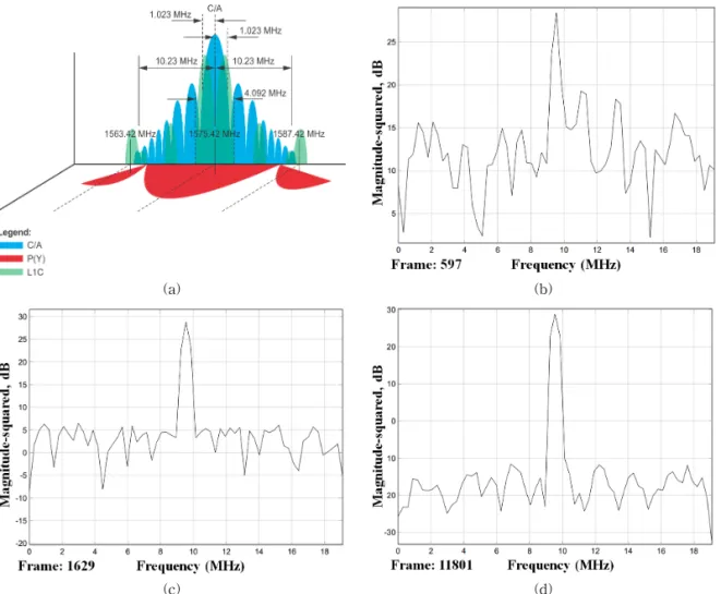
with GPS receiver from anywhere. The GPS com- prises two types of Pseudo Random Noise (PRN) code, including Coarse/Acquisition (C/A) code and Precision (P) code. While C/A code is used by ci- vilian users and is easily attainable to the com- munity, the controlled Precision (P) code com- monly used for military applications. In this study, we focuses only civilian users particularly drone applications and security such as interference de- tection and mitigation, and review only the C/A code. The C/A code are modulated onto the same L1 carrier frequency (1575.42 MHz), which repeats every 1023 bits with a period of one millisecond and modulates at 1.023 megabits per seconds
Anti-interference Methods using Vector-based GPS Receiver Model
Hoan Nguyen Viet
†, Suk-Hwan Lee
††, Ki-Ryong Kwon
†††ABSTRACT
The Global Positioning System (GPS) has become popular and widely used in many fields from military to civilian applications. However, GPS signals are suffered from interference due to its weak signal over wireless channel. There are many types of interference, such as jamming, blocking multipath, and spoofing, which can mislead the operation of GPS receiver. In this paper, vector-based tracking loop model with integrity check is proposed to detect and mitigate the harmful effect of interference on GPS receiver operation. The suggested methods are implemented in the tracking loop of GPS receiver. As a first method, integrity check with carrier-to-noise ratio (C/No) monitoring technique is applied to detect the presence of interference and prevent contaminated channels out of tracking channels to calculate position. As a second method, a vector-based tracking loop using Extended Kalman Filter with adaptive noise covariance according to C/No monitoring results. The proposed methods have been implemented on simulated dataset.
The results demonstrates that the suggested methods significantly mitigate interference of Additive White Gaussian Noise (AWGN) and improve position calculation by 44%.
Key words: GPS, Interference, Vector-based GPS Receiver, Tracking Loop, Carrier-to-Noise Monitoring, Integrity Check, Mitigation
※ Corresponding Author : Ki-Ryong Kwon, Address:
(608-737) 599-1, 45 Yongso-ro, Namgu, Busan, Korea, TEL : +82-51-629-6257, FAX : +82-51-629-6230, E-mail : [email protected]
Receipt date : Nov. 6, 2017, Revision date : Mar. 30, 2018 Approval date : Apr. 14, 2018
†
Dept. of IT Convergence and Application Engineering, Pukyong National University
(E-mail : [email protected])
s†††
Dept. of Information Security, Tongmyong University (E-mail : [email protected])
†††
Dept. of IT Convergence and Application Engineering, Pukyong National University
※ This work was supported by a Research Grant of
Pukyong National University (2017 year)’
(Mbits/s). Each satellite of 32 satellites has a unique PRN code (or C/A code), and every PRN code does not correlate with any other satellite’s PRN code. The GPS follows a form of Code Division Multiple Access (CDMA), which permits the receiver to identify multiple satellites on the same frequency. Apart from the PRN codes, GPS receivers needs to obtain detailed information about each satellite’s position. These information is extracted from navigation message, which is al- so modulated onto the L1 carrier providing in- formation about the satellite’s orbit, their clock corrections. The navigation message has three parts. The first part contains the GPS date and time, plus the satellite’s status and an indication of its health. The second part consists orbital in- formation called ephemeris data, which enables the receiver to calculate the position of the satellite.
The third part, named the almanac, includes in- formation and status concerning all the satellites, their locations and PRN numbers.
In addition, GPS signals are endangered by in- band interferences due to its weak signal over wireless channels. Thus, even a low-power inter- ference such as blocking, jamming, and spoofing can simply mislead GPS receivers. The harmful ef- fect of these interference is not only to prevent po- sition lock (blocking and jamming), but also to de- ceive the receiver false information (spoofing). As
the results of spoofing attacks, the GPS receiver computes an erroneous position, velocity and time solutions (PVT). Generally, when blocking and jamming is occurred, GPS receivers suffers from a loss of signal so they are well-aware. However, the spoofing attack is more menacing than jam- ming because it is unaware [1]. In order to mislead the GPS receiver with counterfeit signal, the spoofing signal is very similar to the authentic GPS signal. The spoofing effects can mitigate with sev- eral techniques in the receiver. Spoofing is hidden attack, thus it is more harmful than both blocking and jamming. Spoofing distorts the C/A code mod- ulations, which enables the counterfeit spoofing signal entering the navigation solution processor [2]. Moreover, as the GPS signal structure is public access, the implementation of an attacker with dis- ruptive capability is not complex. In recent years, the implementation of software-based receiver-in- terference has become more feasible and less cost- ly due to the advances in the Software Defined Radio (SDR) technology. Therefore, anti-interfer- ence techniques on GPS has become a serious is- sue to security and safety of GPS applications [3].
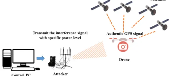
In this study, we focuses on security of GPS appli- cations, and appropriate techniques for interference detection, and mitigation in the GPS receiver as shown in Fig. 1.
This paper presents two approaches based on
Fig. 1. A software-based interference signal generation.
integrity check to detect the presence of interfer- ence and vector-based tracking loop architecture with adaptive noise covariance of Extended Kal- man filter to mitigate the signal outage and the harmful effect on navigation solution measurement.
The remaining part of this paper is organized as follows. Section 2 presents a brief summary on dif- ferent methods of defense against interference. The proposed approaches for interference detection and mitigation in GPS is introduced in Section 3.
Section 4 discusses the experiment setup and re- sults on simulated dataset. Finally, concluding re- marks are given in section 5.
2. RELATED WORKS
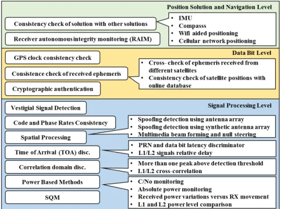
In recent years, several approaches have been proposed for detection and mitigation of interfer- ence [4-9]. Fig. 2 shows a brief summary of inter- ference defense methods in a multilayer layer of GPS functions, including signal processing, data bit and navigation solution [9].
For example, in data bit level, several studies of cryptographic authentication presented their pro- posed implementations considering basic changes to the original GPS signal structure [10, 11]. In case of signal processing level, power-based methods are employed to characterize the received signal quality. Particularly, in normal sky environment, only satellite movement and ionosphere variations contribute to changes in the received signal power.
However, in [6,7], the authors stated that when a much more powerful spoofing signal is injected, C/No monitoring may experience a sudden change which indicate the present of interference. For ex- ample, C/No may reduce by 22 dB-Hz in [8].
Attacker are feasible to be detected, mitigated at any of previous mentioned levels. In additions, a combination of several countermeasure from dif- ferent layers can be developed as cross-level meth- od to combat the sophisticated spoofing attacks.
In [9], the authors presented a summary of sev- eral techniques to counter interference and jam- ming, namely IMU/GPS aiding, spatial, and time-
Fig. 2. Multilayer approach to anti-interference technique.
frequency filtering, and vector tracking loops.
Particularly, IMU/GPS aiding and vector tracking loops approaches can make the GPS to operate in lower C/No levelor within the effect of relatively strong interference in acquisition and tracking loops stage. Another approach is to suppress the interference signals before proceeding by the re- ceivers, which applied in the spatial and time-fil- tering method. These mentioned methods are fea- sibly employed separately or corporately to provide counter measurement to interference of GPS re- ceiver.
3. PROPOSED ANTI-INTERFERENCE METHOD The motivation of this work is to present an an- ti-interference method for a vector-based tracking (VTL) GPS receiver based on power based method (monitoring) for interference detection and miti- gation. Based on monitoring analysis, interference detection method is proposed which is continuously checking the status of multiple tracking loops and look for any irregular variation that can be a trace of interference. If any unusual variation of among multiple tracking channels is detected, an interfer- ence is flagged and the tracking mode of GPS re- ceiver is switched from scalar tracking to vector tracking. The integrity checking is set some iso- lation threshold based on pseudo-range, and pseu- do-range errors and values to exclude the chan- nel’s discriminator output measurements. Vector tracking mode can suppress the effect of signal outage and keep tracking while the Extended Kalman Filter of the vector tracking receiver ig- nores measurement of those tracking channels by integrity check results and mitigated the effect of interference signal by adjust adaptive process noise covariance matrix based on status. When the integrity check detects that interference is moved away, the vector-based receiver switches back to estimate the measurement of the discarded track- ing loops.
In details, the proposed VTL has several mod- ifications, (1) the adaptive switching mode with VTL assisted STL is carried out by integrity check, (2) power-based method for interference detection are equipped into tracking loops as Variance Summing Method algorithm in order to C/N
0mon- itoring and (3) a noise covariance matrix is calcu- lated as a function of C/N
0make Extended Kalman Filter (EKF) more robust against interference.
Particularly, the proposed VTL is implemented as vector delay/frequency lock loop (VDFLL) in non- coherent architecture in a software GPS receiver as shown in Fig. 3.
This section covers the detail of vector tracking loop workflow and implementation. Each channel contains code phase/ carrier frequency discrim- inator and code/ carrier numerical controls oscil- lators (NCOs). The correlation output of I and Q prompt channels is passed to the C/N
0estimation algorithm and code phase/carrier frequency dis- criminator. The discriminator outputs are used to generate code phase error (pseudo-range error) and carrier frequency error (pseudo-range rate)
Fig. 3. The proposed vector tracking loops VDLL/VFLL
architecture.
measurements. Then these error measurements are fed to the EKF to correct its state vector. After the pseudo-range error and pseudo-range rate er- ror are predicted by using the updated state vector.
Finally, the updated code phase error and carrier frequency error are fed back into the code and car- rier (NCO).
There are two important parts of this proposed non-coherent VTL, namely the discriminator algo- rithms and Extended Kalman Filter. Once ini- tialized, VTL begins to (1) generate local replicas and correlate them with the incoming signal by discriminator algorithm, (2) estimate the errors and correct the predictions and start over again to form a closed loop by Extended Kalman Filter. In details, for a measurement of the carrier frequency error, the four-quadrant arctangent FLL discriminator is used.
(1) (2) (3) I
p(k), Q
p(k) are in-phase prompt and quadrature prompt correlator outputs at time k, I
p(k+1), Q
p(k+1) are in-phase prompt and quadrature prompt correlator outputs at time k+1. The pseudo-range rate errors of each channel can be calculated by (4) where f
cfis the carrier frequency. For code tracking, a non-coherent early minus late discriminator is used to calculate the code phase error.
(5)
I
E, Q
E, I
L, Q
Lare in-phase early, quadrature ear- ly, in-phase late, quadrature late correlator outputs respectively. The pseudo-range errors of each channel can be calculated by
(6) where f
C/Ais the nominal frequency of C/A code.
3.1 Interference Detection with C/No Monitoring and Integrity Check
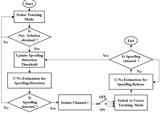
As you can see from the Fig. 4, the integrity check implemented in this works focuses on the tracking loops to counter problems of interference or GPS signal outages and the coupling channel
Fig. 4. Integrity check workflow.
failures ‘s disadvantage of VTL. The performance of general tracking loops is deeply dependent on the integrity check. If a failure, error and interfer- ence is detected in one channel, the working mode of tracking loop is switched from STL to VTL.
However, the previous normal state of STL navi- gation solution results are used to initialize the VTL. Moreover, the integrity check is also applied to counter coupling fault channeling. If errors are detected in several channels, then these channels are isolated from navigation solutions estimation.
As the results, integrity check helps VTL system to prevent the failure of tracking in one channel affecting the entire vector. The integrity checking is set some isolation threshold to exclude the chan- nel’s discriminator outputs, like pseudo-range, pseudo-range rate errors measurement. Moreover, it is feasible of using a vector receiver enables code and carrier tracking during GPS outages of single channel as long as there are four channels for cal- culating a position, velocity and time solution.
A part from pseudo-range, pseudo-range rates isolation threshold, a carrier-to-noise ratio (C/No) estimation based integrity check method is im- plemented to detect sudden signal outages, which can indicate the interference attack. The measure of C/No is fundamental to determine the tracking loop status. For instance, in case of low C/No like 30 dB-Hz, conventional tracking loops experience a rapid increase of tracking errors, or even lose locked of satellite signal [10]. To estimate C/N
0, the Variance Summing Method (VSM) algorithm is applied. The VSM method is described in [11], and is based on computing the mean and variance of the tracked in-phase (I) and quadrature (Q) sig- nal components, from which noise and signal pow- er levels are estimated, and the C/N
0is computed.
Each accumulated I and Q values in 1ms interval are used to calculate the time series Z
kwith mean
and variance
(7)
(8) (9) where K is the number of samples. The average carrier power is calculated by
(10) where N is the number of samples in the time ser- ies Z, and A is the signal amplitude at the front- end output. For the noisy part of I and Q, the noise variance is defined as follows.
(11) In summary, the integrity checking is set some isolation threshold to exclude the channel’s dis- criminator outputs. Pseudo-range measurements are rejected if they exceed ±150 m and pseu- do-range rate measurements are rejected if they exceed ±10 m/s. These thresholds are based on the operating ranges of the discriminators. Measure- ments are also rejected from a channel if its esti- mated C/N
0ratio is below 25 dB-Hz.
3.1 Interference Mitigation with Extended Kalman Filter
The errors of position, velocity, clock bias and drift are chosen as the states of Kalman filter
(12) where the symbol δ represents an error in a state, x, y, and z are the receiver’s Cartesian coordinates position, “.” dot above value represent its time de- rivative, is clock bias and clock drift re- spectively. The discrete-time Markov process equation as follows
(13)
where the matrices
, T is the time du-
ration between the kth and k+1th epoch, and proc-
ess covariance matrix is defined as follows
(14) Discriminator outputs of all satellites are input into Kalman filter as measurements. The measure- ment states of the EKF are the pseudo-ranges and pseudo-range rates residuals of all satellites in view:
(15) where j is the number of tracked channels or visi- ble satellites. As for Kalman filter correction stage, the corrected state estimate equation as follows
(16) where the corrected covariance matrix is denoted as
(17) Kalman gain
(18) Measurement function
(19)
where the terms a
x,m, a
y,mand a
z,mare the elements of the line-of-sight unit vector from the receiver’s position to the mth satellite.
Q
kand R
kis the covariance matrices for process and measurement noises respectively.
In order to update measurement estimation, the measurement vector z are included in the correc- tion step in EKF. In a Kalman filter, the process and measurement noise covariance matrices are the most important parameters determining the performance of the filter. In the proposed VTL, the Q matrix represents the uncertainty in the dynam- ics of the user and the R matrix represents the noise terms in the discriminator output. The co- variance matrix of process noise W
kis denoted as Q
k[12].
(20) where Q
dyncorresponds to the three-axis user dy- namics and Q
clkcorresponds to the equivalent dy-
namics caused by clock errors.
(21) where Q
11is the clock bias noise term and Q
22is the clock drift error term. The measurement noise matrices R
kcontains pseudo-range δρ and pseu- do-range rate residuals δρ˙ of the discriminator output, which is calculated as a function of C/No [13].
(22)
(23)
(24) where T is the integration interval used to generate discriminator outputs (20 ms), ρ
eis pseudo-range error (meters), β is PRN chip length (293,3 meters for C/A code) and R(ρ
e)= , and the variance summing method algorithm in Section 3.1 is used to estimate C/No.
4. SIMULATION RESULTS
In this section, the benefits of carrier-to-noise ratio estimation algorithm VSM for detecting in- terference (e.g., Additive White Gaussian Noise (AWGN)) are justified. In addition, the ability of VDFLL to operate at low C/N
0and momentary blockage are investigated and also verified.
4.1 Simulation Setup
The software-defined GPS receiver is imple- mented in MATLAB environment based on [14,15].
In order to investigate the behavior of the proposed
VDFLL, simulated data is generated by Simulink
GPS signal simulator. The generated digital IF da-
ta comparable to a real GPS RF-front end is con-
figured at an intermediate frequency of 9.548 MHz
and sampling frequency of 38.192 MHz. Resulting
digital IF data is processed in a reconfigurable
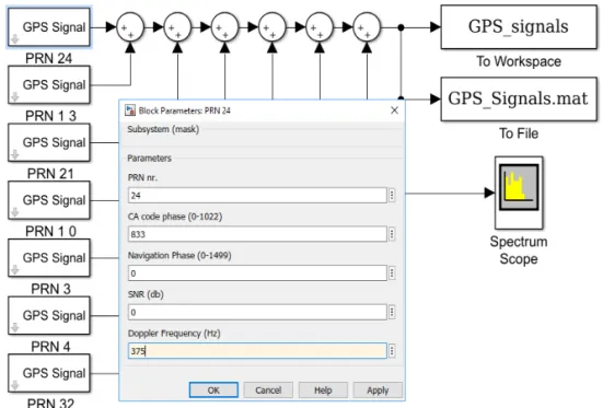
tracking algorithms. Tracking algorithms like stand- ard scalar tracking and vector tracking (VDFLL) algorithms are simulated and compared. For this work, seven GPS satellites (PRN number 24, 13, 10, 21, 3, 4, and 32) are visible as shown in Fig. 5.
Each of the satellites has different values of PRN (range from 1 to 32), C/A code phase (Range from 0 to 1022), Navigation Phase (Range from 0 to 1499), Doppler frequency (Hz), and SNR (dB) are adjusted by changing the values in subsystem mask. The VCO of C/A code generator is con- figured with intermediate frequency (IF) and sam- pling frequency at 9.548 MHz and 38.192 MHz respectively. In case of C/A code generator, the in- itial phase is set to 0, while the initial phase for P(Y) code generator is set to π/2. Seven GPS satel- lites (PRN number 24, 13, 10, 21, 3, 4, and 32) was generated with configuration of code phase, Doppler frequency in Table 1.
4.2 Experimental Measurements
To verify the GPS signal generation is correct, the spectrum of digitized IF data, acquisition re-
sults and C/No monitoring results are presented.
GPS signal strength is an important parameter to describe the performance, determine the status of tracking and control of a GPS receiver. There are two types of display GPS signal strength, namely signal-to-noise ratio (SNR) and carrier-to-noise density ratio (C/No). For this work, the noise gen- erator can configure different SNR level by adding Additive White Gaussian Noise (AWGN) into digi- tal IF signal. Fig. 6 shows the result of GPS signal spectrum scope compared to the reference with a
Fig. 5. SIMULINK Model of GPS Signal Generator with 7 satellites.
Table 1. Satellites configuration in term of code phase and Doppler frequency
GPS signal generator setup PRN(Satellite)
Number Code Phase
(chips) Doppler
Frequency (Hz)
24 833 375
13 926 1661
10 129 3720
21 934 -2739
3 646 -3765
4 99 3658
32 284 -117
different SNR level. The frequency spectrum of generated GPS IF signal is centered and sym- metrical with respect to the carrier frequency 9.548MHz as the result of summing of two BPSK modulated signals having a carrier frequency of 9.548MHz. Thus, this spectrum clearly classifies the correctness of simulated GPS IF signal.
The performance of the acquisition module in a software GPS receiver is tested for 7 visible satel- lites (13, 24, 21, 10, 3, 4 and 22) used in the GPS signal generation. The acquisition results of PRN- 24, and 10 plotted in Fig. 7 show distinct peaks and their corresponding code phase are exactly match- ed with the values used in signal generation as shown in Table 1. Particularly, the peak of PRN 24 occurs at C/A code phase = 833 chips and fre-
quency = 9.5484 MHz (Doppler frequency = 375 Hz) and the peak of PRN 10 occurs at C/A code phase
= 129 chips and frequency = 9.5517 MHz (Doppler frequency = 3720 Hz).
All 7 satellite signal powers remain constant at about 45 dB-Hz until 50s, then 4 satellites are add- ed (Additive White Gaussian Noise) AWGN inter- ference. In details, PRN21’s signal power is drop- ped down to about 20 dB-Hz for 20s duration and back to 45db-Hz, while PRN 3, 4, and 32 after being down to 20db-Hz remain signal power varies in range of 20 dB-Hz to 30 dB-Hz. Particularly, the power of the signal from satellite 21, 3, 4, 32 is atte- nuated rapidly after 50s. The signal power of satel- lites 21 reduces for about 10 seconds and after that the signal returned to its previous level, however
(a) (b)
(c) (d)
Fig. 6. The reference GPS L1 spread spectrum (a) and the simulated IF GPS signal spread spectrum with different
SNR, (b) SNR=0 dB, (c) SNR=10 dB, and (d) SNR=30 dB.
the signal power of satellite 3, 4, 32 remain at low C/N
0levels. To illustrate, the C/N
0estimation re- sults from only two satellites PRN 21 and 3 are shown in Fig. 8. After 50 s, the C/N
0drops below the threshold 25 dB-Hz, the integrity check is flag- ged to switch the tracking mode from STL to VTL, or VTL is assisted STL. The diagonal terms of the measurement noise covariance matrix of EKF is adjust based on C/N
0, thus VTL provides sufficient accurate estimation to keep tracking of VTL and STL from 40 s to 100 s are demonstrated in Fig.
8a.
The channel PRN 3, 4, 5 are contaminated chan-
nel, its tracking performance degrades leading to tracking errors and causing coupling fault channel (or the tracking error propagates throughout the VTL). Tracking result deterioration in these chan- nels may lead to complete loss of lock. The in- tegrity check bases on C/No monitoring results of these channels to exclude these channels from navigation solutions estimation and prevent the spreading of error into the rest of the VTL. At ap- proximately 70 s in the simulation power of 3 satel- lites 3, 4, 5 are attenuated to 19 dB-Hz below the isolation threshold, which are omitted from navi- gation solutions processing. Therefore, only 4 sat-
(a) (b)
Fig. 7. Acquisition results of (a) PRN 24, and (b) PRN 10.
(a) (b)
Fig. 8. Carrier-to-noise ratio estimation results (a) PRN 21 with interference 20s, and (b) PRN 3 with interference
50s.
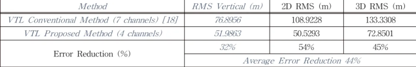
ellites are available for calculation of the navigation solution. The navigation results are plotted in East, North, Up (ENU) coordinate. To verify the pro- posed vector tracking loops’ performance over con- ventional method, the results of navigation estima- tion in ENU coordinates are demonstrated from 50s to 100s. From the Fig. 9, it can be seen that the proposed VDFLL (4 channels) provides less errors of navigation solutions over conventional VDFLL (7 channels).
In addition to visually demonstration, RMS er- rors are compared between conventional and pro- posed methods, which proved that proposed meth- od can reduce the navigation solution estimation error by 44% as in Table 2. Let ΔE
i, ΔN
i, and ΔU
ithe errors in the East, North, and Up (Vertical) components of the ith position estimation sample, RMS vertical error, 2D RMS and 3D RMS error are defined as follow.
(25)
(26) (27) 5. CONCLUSION
In this paper, a GPS receiver architecture based on the vector tracking loops for detection and miti- gation of interference is presented. Among various advantages of vector tracking loop, we focuses on the feasibility of vector tracking loop to operate in harsh conditions such as low C/No levels, high dy- namics and to bridge partial signal outages due to interference of Additive White Gaussian Noise.
Moreover, the proposed vector delay/frequency lock loop (VDFLL) also introduces a solution to channel fault coupling’s drawback of conventional vector tracking loop. For this purpose, C/No esti- mation algorithm is applied to detect the interfer- ence and the possible error in each channel to pre- vent the failure of tracking in one channel may af-
55 60 65 70 75 80 85 90 95 100
-150 -100 -50 0 50 100 150
Coordinates variations in UTM system
Times (sec)
Variations (m)
E VTL Conventional Method N VTL Conventional Method U VTL Conventional Method
(a)
55 60 65 70 75 80 85 90 95 100
-100 -80 -60 -40 -20 0 20 40 60
Coordinates variations in UTM system
Times (sec)
Variations (m)
E VTL Proposed Method N VTL Proposed Method U VTL Proposed Method