*1 Received on July 9, 2010; accepted on August 30, 2010
*2 Div. of Wood Engineering, Dept. of Forest Resources Utilization, Korea Forest Research Institute, Seoul 130-712, Korea
† Corresponding author : Kweonhwan Hwang (e-mail: [email protected])
Shear Performance of Hybrid Post and Beam Wall System Infilled with Structural Insulation Panel (SIP)*1
Kug-Bo Shim*2, Kweonhwan Hwang*2†, Joo-Saeng Park*2, and Moon-Jae Park*2 ABSTRACT
A hybrid post and beam shear wall system with structural insulation panel (SIP) infill was developed as a part of a green home ‘Han-green’ project through post and beam construction for contemporary life style. This project is on-going at the Korea Forest Research Institute to develop a new building system which improves Korean traditional wet-type building system and stimulates industrialized wood con- struction practice with pre-cut system. Compared to the traditional wet-type infill wall components, the hybrid wall system has benefits, such as, higher structural capacity, better thermal insulation performance, and shorter construction term due to the dry-type construction. To build up the hybrid wall system, in previous, SIP infill wall components can be manufactured at factory, and then inserted and nailed with helically threaded nails into the post and beam members at site. Shear performance of the hybrid wall system was evaluated through horizontal shear tests. The SIP hybrid wall system showed higher maximum shear strength, initial stiffness, ductility, yield strength, specified strength, and the specified allowable strength than those of post and beam with light-frame wall system. In addition to this, the hybrid wall system can provide speedy construction and structural and functional advantages including energy effi- ciency in the building system.
Keywords : post and beam shear wall, structural insulation panel, pre-cut, infill wall, horizontal shear test, shear strength
1. INTRODUCTION
Recently, wooden constructions have been in- creasing steadily. To meet the needs for specific Korean wooden dwellings, the effective utilization of domestic wood as structural members on tim- ber construction has issued, and several studies have been conducted to compete with the re-
quests[1]. The structural members applied to tra- ditional houses were excessively over-sized enough to resist the high dead load of roofing tiles. The infill wall of the house is consisted of mud (soil) with some supporters and binders inside of the post-beam frame. But, it is inevitable to pay much time and cost for the wall structuring with the traditional components each other, up to com-
pletion of a traditional wooden house. Komatsu et al.[2] suggested a desirable application meth- od with a pre-fabricated mud wall and test re- sults for a modernized mud wall system. Therefore, for the establishment of modernized construction system, it is necessary to shorten and save the member processing and construction time. For the modernization and mass production, tech- nologies of machine pre-cut and pre-fabrication of structural members, post, beam, wall ele- ments etc., should be applied into the wood construction.
Considering the amount and proportion of do- mestic Japanese larch (Larix kaempferi), fol- lowed by Korean red pine (Pinus densiflora), it is much more reasonable to use these wood species as structural members, post and beam, with full size in the circular or rectangular forms with a specific consideration of high effective lumber yields preferentially and as engineered wood products such as glued laminated timber (glulam) for the next choice. However, the use of big-sized solid wood as structural members is apt to be led to a bit much higher costs by dry- ing process, where moisture content should be fit to at least 18% over all inside of the mem- bers evenly. On the contrary to this, for the per- fect (even) drying, much more cost and time than dimension lumber are needed. Big-sized log or timber can be checked or deformed dur- ing drying as well, which lowers the wood quality, the visual lumber grade and the wood strength.
As a solution for above reviews, dried solid wood and glulam as structural members should be used onto wooden house. In addition, for the infill wall components, light-frame construction and structural insulated panels (SIP) can be applied. In the general wooden building in Korea, the structural oriented strand board (OSB) is used widely. SIP is a sandwich panel manufac- tured by adhering two OSBs on both sides as
surfaces with an expanded polystyrene (EPS) panel as the core. It is one of the hybrid com- posites to compete with structural and insulation functions.
In addition, nail connections might be adopt- ed for the sheathing of infill wall as the sim- plest jointing skill. All the structural members would be pre-cut for rapid, modular, and mass production. In this system, post-beam frame structure is in charge of vertical load and infill wall component be in horizontal one. To exam- ine the combination (hybrid) effects of the wall systems, horizontal shear tests should be con- ducted to ensure the safety and reliability of a wooden house.
In this study, horizontal shear tests for the hybrid shear walls, post-beam frame and infill shear walls with light-frame and SIP, were con- ducted and their shear properties were examined.
2. MATERIALS and METHODS
Basically, all the structural members’ jointing for post-beam frame and sheathing were ori- ented to the construction of modernized wooden housing, which leads to the intersection of mod- ern and traditional wooden construction.
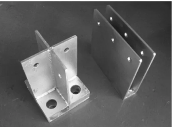
Post and beam members were processed by machine pre-cut. Drift-pin connection for the post base and beam end joints, and nailed con- nection for the infill wall components were adopted. Drift-pin connection is one of the sim- plest jointing methods to build up the heavy timber structures easily. In addition, if the pin- ned holes would be plugged up with a wood piece, the connected parts, mainly steel con- nectors, of the connection could be invisible from outside of the infill shear wall structure, which could exhibit natural wood figures and give aesthetical and natural stability on the whole structures.
Fig. 1. Used connectors (t = 6 mm), post base (L) &
beam end (R).
2.1. Materials and Jointing
The structural members were Japanese larch structural glulam, 10S-30B grade, followed by the Korea Standard[3]. Generally, moisture con- tents of each lamination for glulam were below 15%.
Drift-pins in 16 mm diameter were inserted into each machine pre-cut pinholes on the mem- bers with each connector as shown in Fig. 1. The thickness of steel plates for each connector, was 6 mm to strengthen the previous connector with 4.5 mm[1]. The clearance was 1 mm for the pinholes on connectors and above 2 mm for the slot on post and beam members. The frame specimen was built up by inserting each con- nector into the slotted parts on the members, then four drift-pins were inserted into the post-base connections and three pins were into the beam end connections. Finally, beam mem- ber was inserted onto the post, where the beam end connectors were set up already. For the shear wall specimens, the sheathing panels and studs were nailed, where nails were galvanized helically threaded nails with 3.2 mm diameter and 80 mm length.
For the shear wall specimens, frame working was the same as frame specimen and then OSB
or SIP was sheathed with driving galvanized helically threaded nails into the stud and plates.
The nails are openly used for most of wooden construction sites, in Korea[1]. For the NSW specimen, OSBs were sheathed at both sides of studs with stud interval of full width (about 1200 mm) of the OSB, because of the compar- ison with SIP specimen’s stud space. Also, the nailing pitch was 150 mm around sheathing panels’ outside. In the same manner, SIP shear wall was built up. But, considering the structure of SIP, the SIP unit was inserted into the stud, and then nailed. For both shear wall specimens, the top plate was nailed onto the beam member and bottom plate and sill were nailed finally. In the real construction, all the post and beam members are settled down onto foundation or on sill member, then the wall sheathing is conducted. In the case of SIP shear wall, the last SIP panel should be sheathed with the same manner of NSW specimen’s built-up.
2.2. Test Specification
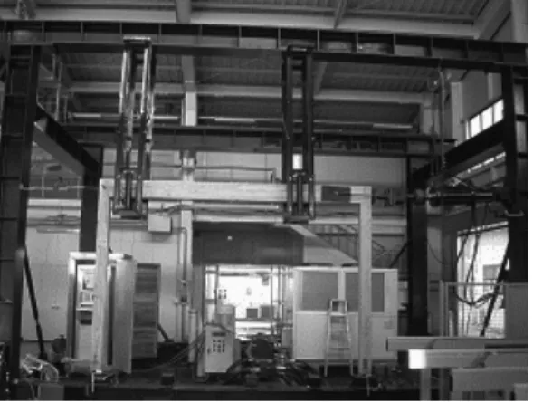
All the dimensions of tested specimens are 3.600 mm span and 2,490 mm height as shown in Fig. 2. The full stroke of oil-jackie was ± 100 mm attached with 150 kN capacity of load cell.
In the Figs. 2 and 3, tested specimens, frame and shear walls, were guided by rollers on both sides and at two points of beam not to occur eccentricity during tests. For the shear wall speci- mens, the eccentricity-proof guiders were equip- ped from bottom steel frame to top steel frame entirely.
2.3. Test Methods
Horizontal shear tests, based on the Korean Standard (KS) for frame and wall structures, were conducted[4]. Other standards[5,6] were referenced as well for the precise test. Lateral loads were imposed cyclically to the neutral axe
Fig. 2. Post-beam frame.
Fig. 3. Hybrid shear wall.
of the tested specimen’s beam, the loading was regulated in the order of 5, 10, 20, 30, 40, 50, 60, 80, and 100 mm displacement. Following the test method, five cycles, 10, 20, 30, 40 and 50 mm, were conducted three times under the same cyclic condition. To measure precise de- formation angle of each specimen, LVDTs were installed at post base joint for the uplift and horizontal displacement of both posts, at beam end joint for the horizontal displacement of beam, and at sheathed oriented strand board (OSB) for the slip of adjoining OSB. Shear load and each deformation data were measured by a data acquisition system simultaneously and the
loading was controlled by computer-controlled system over all the test processes. The static loading speed was 1 mm/sec.
2.4. Evaluation of Shear Properties
For the lateral test of shear wall system and the evaluation of relationship between shear strength and deformation, the present standard [4] is only able to be applied for light frame construction. To meet with the needs, new test- ing method for the post-beam structure should be examined. Equation (1) presents the calcu- lation of specific shear strengths by the present standard.
' Φ
max' u
3 2 1
b a d G P
b S P
b h
×
=
=
− −
=δ δ δ
(1)
where Φ = shear deformation, Su = maximum shear strength, G = shear rigidity, δ1 = horizon- tal pure displacement at the loading point (m), δ2 = horizontal pure displacement at the bot- tom (m), δ3 = vertical pure displacement (m), h = distance between measuring point for hori- zontal displacement (m), b = distance between measuring point for vertical displacement (m), Pmax = maximum shear load or load at 50 mm of displacement (N), b' = width of shear wall (m), P = a third of Pmax (N), a = height of shear wall (m), d = total displacement (mm).
According to the present standard[4], if the maximum shear load could not obtained by shear test, it is permitted to substitute the max- imum shear strength with the load at 50 mm displacement. The load is about the load level of 50 rad. for the tested specimens in this study.
To consider the seismic design or traditional
Notes: Pmax: maximum load, Py: yield load, Pu: maximum load by bi-linear analysis, m: ductility factor, Ds: structural factor, S: absorbed energy, K: initial stiffness, δy: deformation at the Py, δv: deformation at the beginning of Pu, δu: deformation at 0.8 Pmax
Fig. 4. Bi-linear analysis[7].
post-beam structures, further test for the whole load-deformation relations should be conducted on the shear wall. Progressive and aggressive suggestions are needed to the revision or estab- lishment of new test method for the various types of shear wall tests and to get more load-deformation relations. In Japan[2,7], they obtain 80% of maximum load (Pmax) for the evaluation of shear load factor and allowable shear strength. In this study, shear tests were conducted up to the maximum capacity of actuator.
Basically, as given in Fig. 4, the evaluations for the shear load-deformation relationships of the shear walls were conducted by the present Korean standard, and the Japanese method[4,7]
was referenced to obtain allowable shear strengths for each tested specimen.
The processing of bi-linear evaluation was: at first, an envelope curve should be obtained from tested results of load-deformation relations.
Using 0.1, 0.4, and 0.9 Pmax, a yield load Py
and stiffness K are determined. An ultimate strength Pu is determined so as to make the tra- pezoid area surrounded by line ④, ⑤, and δu
equivalent to that of S surrounded by envelope curve. The ductility factor m is defined as δu/ δv. A factor Ds, which characterizes equivalent strength of the structure in the aspect of energy dissipation, is also determined as Ds = 1/(2m-1)0.5. From these characterized values and a specific shear strength at 1/120 rad., the minimized al- lowable shear strength can be induced.
In addition, for the selection of allowable shear strength of a shear wall, the minimum strength should be chosen by Equation (2), based on the AIJ method[7].
⎪⎪
⎪
⎭
⎪⎪
⎪
⎬
⎫
⎪⎪
⎪
⎩
⎪⎪
⎪
⎨
⎧
=
s u y
D P P
P P
P
2 . 0 3 2 (min)
120 max 0
(2)
where Po: standard allowable shear strength, Py: yield strength, Pmax: maximum strength, P120: shear strength at 1/120 rad., Ds: structural factor, Pu: maximum load by bi-linear.
AIJ method[4] was developed to design more efficiently for the wooden construction. The shear deformations of the heavy timber con- struction are more ductile than steel and RC constructions. From the specific characteristics of the wooden structure, the ductility is mainly affecting on the determination of allowable shear strength.
3. RESULTS and DISCUSSIONS
3.1. Frame Specimen
Fig. 5 gives the curve of shear force and de- formation angle for the frame specimen. Also, specific loads (yield shear load and load at 1/120 rad.), stiffness, and characterized ultimate load for the energy dissipation, are drawn in the
Fig. 5. Shear properties of frame specimen. Fig. 6. Shear properties of light-frame infill wall.
Fig. 7. Shear properties of SIP infill wall.
graph. The frame specimen gives good deforma- tion properties, enduring continuous load in- crease for the whole loading schedule and max- imum capacity of machine stroke. Also, the ma- chine set-up was changed to get maximum shear load and further deformations. But, it was un- able to get the maximum load within machine full stroke (100 mm). The post base joint was a little uplifted and deformed with continuous shear deformation of full frame; beam end joint wasn’t deformed so much.
3.2. Hybrid Shear Walls
3.2.1. Infill of Light-frame
For the useful shear properties of light frame structure, effects of stud spacing, sheathing ma- terial and so on were reported by a domestic re- searcher[8]. Basically, it is well known that the number of sheathing nails is the main factor for the shear strength of the light frame construction.
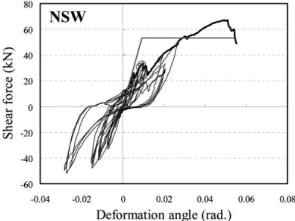
Fig. 6 gives the relationships of shear force and shear deformation angle for the shear wall specimen infilled with light-frame (NSW). Con- trary to the frame specimen’s shear character- istics, NSW specimen had much higher stiffness and load capacity. Although some failures were shown in the early stages, the entire shear wall
system endured after the failures with good load capacities.
3.2.2. Infill of Structural Insulated Panels
Fig. 7 gives the relationships of shear force and shear deformation angle for the shear wall specimen infilled with structural insulated panels (SIP). Contrary to the frame and NSW speci- mens’ shear characteristics, SIP shear wall had much higher stiffness and load capacity without significant early failures. The entire shear wall system endured after the failures with better load capacities than the NSW specimen. From this
Fig. 8. Shear properties of infill wall with structural insulated panels.
Table 1. Shear strengths of each specimen (unit : kN/m) Specimen Pmax Py P120 PS Pas K
(kN/rad.) Frame 3.2 1.9 0.8 1.0 0.5 303
NSW 18.6 9.1 8.5 7.2 3.8 3,458 SIP 19.7 12.2 11.6 8.6 4.6 4,874 Note: Pmax: maximum load, Py: yield load, P120: load at 1/120 rad., PS: load determined by the bi-linear method[6], Pas: short-term allowance shear load, K:
initial stiffness
result, it is clear that the SIP infill wall system have a good structural property. Even though the same nails were driven into the both infill walls, NSW and SIP specimens, the further strength increase of shear performance in SIP specimen seemed to be induced by the bonding effect of EPS core and two sheets of OSBs.
3.3. Shear Strengths
3.3.1. Envelope Curves
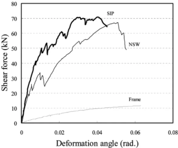
Fig. 8 is the curves of enveloped values for the whole tested specimens in a graph. From the entire cyclic curves for each specimen, the maximum load was extracted from the curves within push loading, positive loading from zero to 80% maximum load after failure. As men- tioned previously, it was impossible to obtain 80% maximum load beyond failure for the frame specimen.
From the view of energy dissipation, the shear performance of SIP seemed to be lower than that of NSW. But, if the real deformation would be considered on design level, i.e. 0.02 (1/50) rad. (about 50 mm deformation), the shear performance of SIP is much higher than that of
NSW specimen. As the strength of the light-frame system can be shown by the nail connections, the maximum loads were almost same each oth- er for NSW and SIP specimens.
3.3.2. Shear Strengths
Table 1 gives the specified shear strengths of the whole tested specimens. Shear strengths were characterized by the present standard[4].
The minimum loads were selected for the calcu- lation of allowable short-term strengths, where the two-thirds of maximum strength, yield strength, strength at 1/120 rad. and specific strength con- sidered deformation capacity, were used.
The shear strengths of SIP specimen showed better than NSW specimen and much higher than frame specimen. Also, the initial stiffness of SIP had much better performance than strengths of NSW’s. From these results, it can be said that SIP had much more strength increase in the early stage of the shear performance. This phe- nomenon might be induced by the effects of bonding layer between styrofoam (EPS) core and OSBs. To summarize above results, SIP can act efficiently on the infill shear wall than light-frame construction. In addition, the SIP composite has insulation function with structural performance, which saves labours and times to construct the entire wall system with parted segments’ const- ruction. In this view, the SIP infill shear wall
Fig. 9. Frame specimen.
Fig. 10. Buckling failure of NSW specimen during test.
system will be a good alternative of Korean tra- ditional timber construction.
The traditional Korean buildings and houses were built-up on the foundation stone without any connections and heavy floor-heat system and roof loads. Due to the big-sized members, the vertical load can be restrained easily, but the examination of horizontal load are left still.
Considering these points, for the combination of traditional timber structures and modern infill wall components, the post base joint should be fixed and beam end joint might be connected just not to fail against the vertical load. So, the beam end can be connected by dove-tail joint, because the whole shear strength of a shear wall system is apt to be affected on the infill wall components which is nailed with frame members.
3.4. Failures
3.4.1. Frame Specimen
Fig. 9 shows the failure figures of the frame specimen after test. Entirely, the frame had not any significant failures to affect any decrease of the shear strength.
As shown in Fig. 9, posts were split above slot by the resisting of crossed steel plate on the post base connector whereas beam end con- nection was parted between post and beam.
Also, the bottom of post base connector jointed with base plate (foundation or sill) was uplifted by the rotation of post. Although some failures were observed in post base part, the whole frame system had still a good shear performance.
3.4.2. NSW Specimen
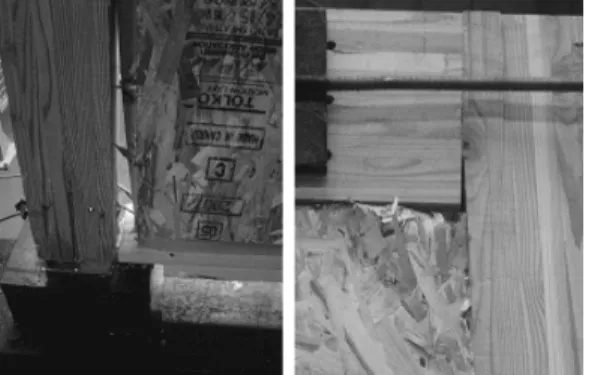
Fig. 10 shows the failure figures of the NSW specimen after test. Even though the frame in the whole wall had not any significant failures, buckling of OSB happened to during test. As in- sufficient studs were installed inside of a both-sided OSB, the shear forces seemed to be rushed into the buckling of the panels. In addi- tion, from the specific characteristics of infill wall system, more severe shear force was loaded into the panels, which could occur collapse of the panels in the corner of the infilled OSB.
Most of the driven nails were remained on the studs. Considering the real condition, NSW will not applied into light-frame construction or in- fill wall system. NSW specification was just ap- plied to this study as a control of SIP system.
3.4.3. SIP Specimen
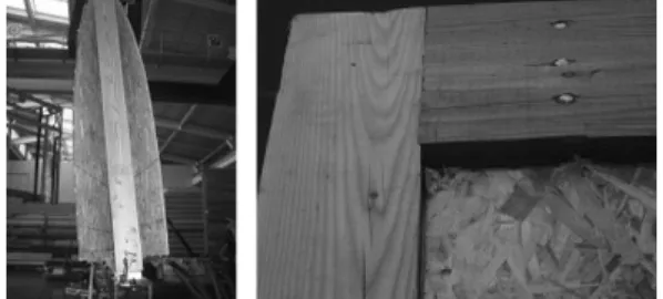
Fig. 11 shows failures of the SIP specimen af- ter test. The entire failure mode was not so dif- ferent with NSW specimen’s, but no buckling of OSB. The collapses in the corner (right in the Fig.) and the gap (left in the Fig.) between post and SIP were observed. Due to the top plate, connected to the beam member, there was not so big gap between post and beam connection.
Fig. 11. Failures of SIP specimen.
4. CONCLUSION
Hybrid wall systems with post-beam frame and SIP infill were developed as a part of a green home project. To meet the needs of tradi- tional post and beam structure with modern housing style, an upgraded building system with industrialized wood construction practice that can be induced by pre-cut of structural heavy timber members, was suggested. For the mod- ernized Korean style housing, infill wall compo- nents instead of the traditional mud wall con- struction, wet-type, the hybrid wall system (dry- type) has lots of benefits, higher structural ca- pacity, better thermal insulation performance, and shorter construction term. To build up the hybrid wall system, SIP infill wall components can be firstly manufactured at factory, and then inserted and nailed with nails into the post and beam members at site. Shear performance of the hybrid wall system was evaluated through hori- zontal shear tests. The SIP hybrid wall system
showed better shear performances than those of light-frame infill wall system. In addition to this, the hybrid wall system can provide speedy construction and structural and functional ad- vantages including energy efficiency in the building system.
REFERENCES
1. Hwang, K., J. Park, and M. Park. 2007. Shear performance of post and beam construction by pre-cut process. Mokchae Konghak 35(6): 1∼12.
2. Komatsu, K., S. Takino, K. Hwang, T. Mori, and Y. Kataoka. 2004. Lateral shear performance of the wooden post & beam structure with pre- fabricated small mud shear walls. Proceedings of the 8th World Conference on Timber Engineering (WCTE2004): 159∼164.
3. KS 2005. Structural glued laminated timber. KS F 3021, Korean Standards Association.
4. KS 2001. Method of shear (racking) resistance test for light-frame wood shear walls. KS F 2154, Korean Standards Association.
5. American Society for Testing and Materials.
2001. Standard Practice for Static Load Test for Shear Resistance of Framed Walls for Buildings.
ASTM E 564-00.
6. International Organization for Standardization. 2003.
Timber structures - Joints made with mechanical fasteners - Quasi-static reversed-cyclic test method.
ISO 16670.
7. Architectural Institute of Japan. 2002. New esti- mation method for shear wall performance. Stan- dard for Structural Design of Timber Structure.
8. Jang, S. 2002. Effects of stud spacing, sheathing material and aspect-ratio on racking resistance of shear walls. Mokchae Konghak 30(3): 97∼103.
![Fig. 4. Bi-linear analysis[7].](https://thumb-ap.123doks.com/thumbv2/123dokinfo/4830534.525403/5.808.96.386.140.350/fig-bi-linear-analysis.webp)