Vol. 31, No. 4 (2021)
209
Co-Precipitation Synthesis and Characterization of Strontium Lanthanum Vanadate Nanoparticles
Huynh Thanh-Nam 1 , Hayk Hacob Nersisyan 2 , Soon-Jik Hong 3 and Jong-Hyeon Lee 1,2,4†
1Graduate school of Materials Science and Engineering Chungnam National University, Daejeon, Republic of Korea
2Rapidly Solidified Materials Research Center, Chungnam National University, Daejeon, Republic of Korea
3Division of Advanced Materials Engineering, Kongju National University, Cheonan, Chungnam, Republic of Korea
4Graduate school of Energy Science and Technology, Chungnam National University, Daejeon, Republic of Korea
(Received March 11, 2021 : Revised March 23, 2021 : Accepted March 24, 2021)
Abstract
Strontium lanthanum vanadate La1-xSrxVO3 (LSVO) is a promising anode material for electrochemical devices, especially for solid oxide fuel cells, thanks to its irregular electrical conductivity. However, the known synthesis methods are incapable of producing well-dispersed LSVO nanoparticles (NPs) with homogeneous size distribution, which partly impedes the applicability of the material. Thus, a new approach to synthesize LSVO NPs with such characteristics is of paramount importance. In the present work, we successfully prepare LSVO NPs with a high dispersion degree and homogeneous size distribution via a modified co-precipitation pathway, followed by hydrogen reduction at a temperature as low as 700oC. The prepared LSVO NPs display uniform sizes in the range of 50 ~ 100 nm and do not contain any secondary phases, according to XRD analysis. The chemical mechanism of reactions that occur to form the LSVO is thoroughly highlighted. The work functions of NPs measured by the UPS analysis are in the 2.13 ~ 3.62 eV range, making the LSVO powders promising for use in thermionic devices. An explanation of the role of Sr substitution in work function values of LSVO is also proposed.Key words
strontium lanthanum vanadate, co-precipitation, perovskite, well-dispersed nanoparticle, work function.1. Introduction
Strontium lanthanum vanadate with the general formula of La
1-xSr
xVO
3(LSVO) (0 ≤ x ≤ 1) is a perovskite-based material that possesses interesting electrical properties.
LSVO exhibits an insulator-to-metal transition with increasing dopant concentration. Plenty of studies have been carried out to probe this unusual conductivity.
1-11)The transition occurs when the Sr content surpasses 0.178; since then, LSVO exhibits p-type metallic behavior with significantly high electrical conductivity. Liu et al.
12)reported the conductivity in H
2atmosphere of the metal- like La
1-xSr
xVO
3of 300 ~ 400 S·cm
−1, which was two orders larger than pure LaVO
3and doubled the values of SrVO
3. In the forms of thin films, La
2/3Sr
1/3VO
3had an electrical conductivity of up to 742.3 ~ 872.3 S·cm
−1at room condition.
13)To explain this transition, Mott et al.
14)and Dougier and Hagenmuller
2)proposed that the metallic behavior stemmed from the Anderson transition induced
by the random distribution of Sr
2+and La
3+ions.
Meanwhile, A. V. Mahajan and colleagues argued that the transition originated from electron correlation effects.
6)LSVO has been widely investigated for applications in solid oxide fuel cell (SOFC) electrodes thanks to its metal-like electrical conductivity and its stability in tough conditions of SOFCs at 800 ~ 1,000
oC.
12,15-22)Renewed interest in LSVO has grown in the last few years since several strategies were implemented to seek novel applications. The p-type La
2/3Sr
1/3VO
3thin films were reported to have high conductivity and high transmission in the visible range, which could be applicable as a high figure of merit transparent conducting oxide.
13)Remarkably, p-type La
2/3Sr
1/3VO
3was also suggested to form a novel type of Schottky diodes when establishing a heterostructure with n-type TiO
2.
23)A Schottky contact is fundamentally realized by a disparity in work functions between a metal and a semiconductor. Thus, to maximize the performance of LSVO-based Schottky contacts, an understanding of
†
Corresponding author
E-Mail : [email protected] (J.-H. Lee, Chungnam Nat'l Univ.)
© Materials Research Society of Korea, All rights reserved.
This is an Open-Access article distributed under the terms of the Creative Commons Attribution Non-Commercial License (http://creative-
commons.org/licenses/by-nc/3.0) which permits unrestricted non-commercial use, distribution, and reproduction in any medium, provided the
original work is properly cited.
the material’s work function is essential.
So far, the method of choice for the production of LSVO powder has been the solid-state reaction (SSR).
SSR was selected not because of its simplicity and mass production capability but because of limitations when synthesizing by wet chemical route due to remarkable solubility of Sr(OH)
2in water. In fact, SSR usually brings about several disadvantages. First, the heat treatment temperatures in SSR are in the range of 1,000 ~ 1,500
o
C,
3,4,12,21,22)which results in a high degree of agglomeration.
Second, since precursor particle sizes vary, the resulting powder is often inhomogeneous in terms of shape, size, and element distribution. The SSR process is also incapable of producing LSVO powder with small particle size and large surface area, which is one of the reasons for the postponement in research on LSVO for SOFCs in recent years. In 2019, Liu
24)proposed a hydrothermal route to produce La
0.7Sr
0.3VO
3, which reduced the heat treatment temperature to as low as 800
oC. In the study, LSVO NPs with good crystallinity and high densification were prepared.
The electrical conductivity of hydrothermally produced LSVO NPs was marginally higher than that obtained from SSR. However, some drawbacks of the hydrothermal process, such as a complicated experimental procedure or a high pressure of gas in the reaction chamber, make it less effective. Therefore, a facile and effective method to synthesize LSVO nanoparticles is still in demand.
Among the nanoparticle production methods, our attention was paid to the co-precipitation method, which is relatively simple and can be adapted to produce high- quality LSVO NPs. Also, it can be scaled up for large- scale production purposes. Therefore, the present work was conducted with a major purpose: to evaluate the feasibility of using a co-precipitation pathway to fabricate well-dispersed single-phase LSVO NPs. To overcome the solubility issue of Sr(OH)
2, the slurry containing hydroxide phases was cooled at 10
oC and then was purified with cooled water. The goal was achieved as LSVO NPs were successfully obtained. The NPs’ morphologies and their formation mechanism are demonstrated. Additionally, we investigated the work function of the collected powders and suggested potential implementations.
2. Experimental Procedure 2.1 Synthesis procedure
For co-precipitation synthesis, La
2O
3(Samchun, 99.9
%), SrCO
3(Samchun, 95 %), V
2O
5(Samchun, 99 %), HCl 36 % (Samchun), and NaOH were used as precursor materials. In the first step, La
2O
3, SrCO
3, and V
2O
5powders in stoichiometric proportions corresponding to 0.1 mol of LSVO were dissolved in 100 ml concentrated HCl at 110
oC. The as-obtained solution was cooled down
to ambient temperature. For precipitation, the solution was treated with NaOH 1M solution under the stirring condition. Then, the slurry was cooled down by immersing the beaker in water at 10
oC in 1 h. This step aimed to reduce significantly the solubility of Sr(OH)
2in water.
Next, the slurry was washed several times with deionized water and acetone and then was dried at 70
oC for 24 h.
The precursor was ground into a fine powder and prepared for the hydrogen treatment, where V
5+in V
2O
5was reduced to lower valence states existing in LSVO. For this, the precursor was loosely filled in an alumina boat and heat-treated in a reducing atmosphere consisting of 90 % N
2and 10 % H
2. Since the hydrothermal route could produce LSVO at a hydrogen reduction temperature of 800
oC, the co-precipitation method was expected to reduce the temperature further. Hence, a temperature range of 500 to 700
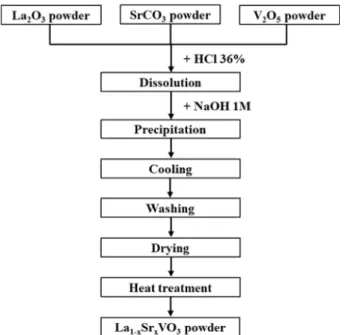
oC was applied in this step to examine the optimized temperature for LSVO heat treatment as well as investigate the effect of heat treatment temperature on the characteristics of LSVO NPs. A flow chart summa- rizing the synthesis procedure is illustrated in Fig. 1.
Also, a La
0.4Sr
0.6VO
3(LSVO-0.6) sample was synthesized by the SSR method as a reference. Here, a mixture containing stoichiometric amounts of La
2O
3, SrCO
3, and V
2O
5was prepared by ball-milling and heat-treated at 1300
oC in 5 h under the reducing atmosphere.
2.2 Characterization methods
The crystal structures and morphologies of LSVO nanoparticles were characterized through XRD analysis (PANalytical X’Pert PRO X-ray diffractometer operated
Fig. 1. Synthesis procedure of LSVO NPs by co-precipitation
method.
with a CuKα radiation (k = 1.5406 Å) source, the Netherlands) and a field-emission scanning electron microscope (JEOL JSM-6700F, Japan). The TEM analysis (Tecnai G2F30 S-TWIN, Thermo Fisher Scientific, USA) was conducted to examine the morphological features of NPs and the elemental distribution in the complex oxide.
For measuring the work function, LSVO NPs were dispersed in ethanol, and the suspension was drop-casted on a Cu substrate to form a film. UPS spectra were taken with a He I emission lamp (hν = 21.2 eV) using K- Alpha+ (Thermo Fisher Scientific). The Fermi level was calibrated by referring to the Fermi level of Cu substrate, and a bias voltage of -10 V was applied.
3. Results and Discussion
3.1 XRD analysis of LSVO powders
La
0.4Sr
0.6VO
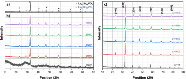
3(LSVO-0.6) composition was chosen to investigate the effect of heat treatment temperature on the characteristics of LSVO NPs. The XRD patterns of powders prepared by SSR and co-precipitation methods are shown in Fig. 2(a) and (b). The product prepared by SSR [Fig. 2(a)] shows the characteristic peaks of La
0.4Sr
0.6VO
3. The peaks are located at 2θ of 23.08, 32.90, 40.60, 47.13, 58.58, 68.78 and 78.24, corresponding to the (101), (002), (220), (202), (222), (123), and (004) planes, respectively. Additional peaks detected on XRD patterns at 28.88 and 31.81 are associated with the La
0.4Sr
0.6VO
4phase.
The main phase in LSVO-06 powders prepared by co- precipitation method and heat-treated at 500 ~ 700
oC is La
0.4Sr
0.6VO
3[Fig. 2(b)]. At a temperature of as low as 500
oC, although peaks of the La
0.4Sr
0.6VO
3phase can be detected, the powder remains amorphous, and peaks of the oxidized La
0.4Sr
0.6VO
4phase are still observed. With
the increasing temperature, the desired phase La
0.4Sr
0.6VO
3becomes more dominant, whereas the peaks accounting for the oxidized phase at 28.88, 31.81, 43.53, and 49.29 show a declining tendency in intensity, indicating a decrease in its concentration. The second phase can barely be recognized in the XRD pattern at 650
oC, and it completely disappears at 700
oC. These results indicate that the LSVO powders can be produced at a heat treatment temperature of as low as 700
oC. This temperature is 100
o
C lower than that of the hydrothermal process and almost half of the SSR temperature.
Furthermore, from Fig. 2(a) and (b), it can be seen that the solid-state reacted powder has sharper diffraction peaks compared to those derived from the co-precipitation method, suggesting the latter method can fabricate particles with smaller crystallite size. Also, there is almost no significant variation in the width of XRD peaks shown in Fig. 2(b) as the temperature increases. This implies that the increment in temperature from 500 to 700
oC does not heavily affect the crystallite size of the products.
A series of La
1-xSr
xVO
3powders with x increases from 0 to 0.8 were then prepared by the co-precipitation method at 700
oC. The XRD patterns of these powders are shown in Fig. 2(c). Characteristic diffraction peaks corresponding to (101), (002), (220), (202), (123), (004), and (323) planes of LSVO are clearly detected, and traces of additional phases is hardly observed, indicating that single-phase LSVO powders are successfully synthesized.
It is noticed that with increasing x, the peaks gradually shift towards higher positions. For example, the peak corresponding to (002) plane is centered at around 22.55 for x = 0, and increases to 22.86, 22.91, 23.08, for x = 0.2, 0.4, 0.6, respectively, and before reaching 23.17 for x = 0.8. This signifies the monotonic change of lattice parameters within the series, i.e., the structural transition
Fig. 2. XRD patterns of: (a) La
0.4Sr
0.6VO
3prepared by SSR, (b) La
0.4Sr
0.6VO
3prepared by co-precipitation method and heat treated at
different reduction temperatures; (c) La
1-xSr
xVO
3with x = 0 – 0.8 prepared by co-precipitation method at 700
oC.
from the orthorhombic phase of LaVO
3to the cubic phase of SrVO
3. Also, it is recognized that the peaks become broadened as x increases from 0 to 0.6 before being narrowed at x = 0.8. This observation is similar to those reported by Liu and colleagues,
24)when they examined the XRD patterns of La
1-xSr
xVO
3(x = 0, 0.1, 0.3, 0.5, 0.7, and 1). The origin of the shifted and broadened peaks is attributed to the random occupations of La and Sr at A-sites in the ABO
3perovskite structure, causing a wide distribution of lattice parameters.
3.2 Dispersity of LSVO powders prepared by co- precipitation method
3.2.1 SEM analysis
Fig. 3(a-d) show the SEM images of LSVO powders prepared by the co-precipitation method. As seen from the figures, the examined samples are similar in morphology.
All powders are composed of fine particles, and no
aggregated cluster can be found. This indicates that LSVO powders synthesized through the co-precipitation pathway have a high degree of dispersion. High-resolution SEM images of the representative La
0.8Sr
0.2VO
3sample are demonstrated in Fig. 3(c) and d to analyze further the morphology of the collected NPs. These particles are rod-like in shape with dimensions below 100 nm. The shape is probably the result of primary particles’ sintering at 700
oC.
To examine the distribution of elements in the prepared La
1-xSr
xVO
3(x = 0.2 - 0.8), EDS analysis was also performed in the areas shown in Fig. 3(a-d). The estimated percentages of elements and the atomic La/Sr ratios obtained from EDS are tabulated in Table 1. To determine whether the elements are uniformly distributed, we focus on the relative ratio between the atomic percentage of La and Sr because the amounts of V were fixed during the synthesis process, and the computed
Fig. 3. (a-d) Morphologies of LSVO powders prepared by co-precipitation pathway; (e,f) High resolution SEM images (×30,000 and
x50000, respectively) of the representative La
0.8Sr
0.2VO
3powder.
contents shown in Table 1 are likely to equal to the sum of La and Sr (with an immaterial degree of variation).
The oxygen contents are not taken into account since the computed values are considered somewhat inaccurate due to the EDS’s limitation when measuring light elements.
In all samples, the La/Sr ratios are almost close to the stoichiometrically desired values, albeit with slight Sr deficiencies. The two with low contents of Sr have better stoichiometry compared to the others. The La
0.8Sr
0.2VO
3has almost the exact stoichiometric composition. The variation is about 0.01 in the sample with x = 0.4, while the differences are 0.02 and 0.03 in the samples with x = 0.6 and 0.8, respectively. The differences, however, can
be neglectable because they are just 5 % or less varied from the desired ones. The slight deficiency of the Sr dopant can be interpreted based on the dissolution behaviors of Sr(OH)
2during the precipitation and washing stages. Although the cooling temperature was reduced to as low as 10
oC, there can still be a limited amount of Sr(OH)
2precipitate dissolving into the solution. The amount of dissolved Sr(OH)
2increases with increasing Sr content in LSVO. This explains the larger variation in the La/Sr ratios with increasing x.
To check the compositional homogeneity of NPs, the elements’ distributions at various points in the LSVO-0.6 prepared by the SSR and co-precipitation methods were analyzed by SEM/EDS. The results are presented in Fig.
4 and Table 2. LSVO NPs prepared by the co-precipitation method show the La/Sr ratios of 0.39/0.61 and 0.41/0.59, which slightly fluctuate around the stoichiometric value.
Meanwhile, points taken in the SSR product show significant variations, as the ratios are 0.46/0.54 and 0.53/0.47.
3.2.2 TEM analysis
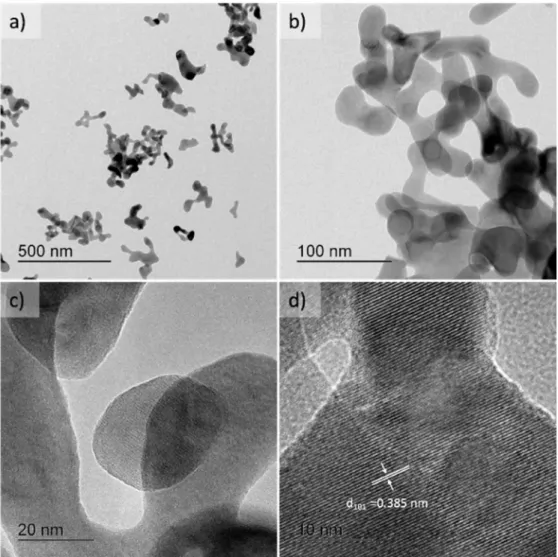
TEM analysis was performed for the LSVO-0.6 sample to investigate further the morphology of the material.
Fig. 4. EDS spectra at certain points in La
0.4Sr
0.6VO
3samples prepared by (a) co-precipitation and (b) SSR methods.
Table 1. Elemental distribution in LSVO samples measured by SEM/EDS.
Atomic%
La
0.8Sr
0.2VO
3La
0.6Sr
0.4VO
3La
0.4Sr
0.6VO
3La
0.2Sr
0.8VO
3O 51.45 54.46 48.20 53.21
V 23.98 22.19 25.67 23.54
Sr 4.87 9.17 15.15 17.83
La 19.70 14.18 10.98 5.42
La/Sr 0.80/0.20 0.61/0.39 0.42/0.58 0.23/0.77
Fig. 5 shows the TEM images of the sample at different magnifications. Fig. 5(a) and (b) depict LSVO-0.6 NPs in the form of rods with lengths of around 100 nm and widths of 50 nm or less. These particles are relatively consistent in shape and size, which is in agreement with the SEM observation. Besides, small aggregated clusters with dimensions of about 100 × 200 nm can also be seen.
The rod-like shapes might be developed due to the
agglomeration of primary particles at 700
oC. A typical LSVO-0.6 primary particle possesses a spherical shape with dimensions around 20 nm [Fig. 5(c)]. The crystallinity of the particle is reflected in Fig. 5(d). Clear lattice fringes with an interplanar spacing of 0.385 nm, corresponding to (101) plane as detected from XRD pattern, are found.
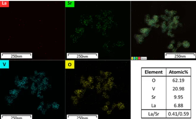
Again, for compositional homogeneity investigation, TEM/EDS was scanned over a small cluster of LSVO- 0.6 nanoparticles. The elemental maps and composition are displayed in Fig. 6. All elements are distributed universally without any localization within the examined cluster. The La/Sr ratio is about 0.41/0.59, which is close the values reported in the previous section.
In short, we can conclude that our co-precipitation pathway is capable of producing LSVO NPs with better dispersity and compositional homogeneity compared to the SSR. This improvement is thanks to the enhanced diffusion processes in the precipitate and precursors. On the other hand, the large particle sizes of raw materials in the SSR route impede such a diffusion. The as-discussed Table 2. Elemental distribution in La
0.4Sr
0.6VO
3samples prepare by
co-precipitation (spectrum 1 & 2) and by SSR (spectrum 3 & 4).
Atomic%
Spectrum 1 Spectrum 2 Spectrum 3 Spectrum 4
O 59.38 57.61 49.68 55.07
V 19.83 20.80 24.37 21.11
Sr 12.63 12.67 14.12 11.26
La 8.16 8.92 11.84 12.57
La/Sr 0.39/0.61 0.41/0.59 0.46/0.54 0.53/0.47
Fig. 5. TEM images at different magnifications of La
0.4Sr
0.6VO
3prepared by co-precipitation method.
inhomogeneity appears as a result of the diffusion- induced mechanism of phase formation.
3.3 Chemistry of Synthesis Procedure
The dissolution of lanthanum oxide (La
2O
3), strontium carbonate (SrCO
3), and vanadium oxide (V
2O
5) mixture in concentrated hydrochloric acid (HCl) at 110
oC produced a blue color solution, which was due to the V
5+to V
4+reduction resulting in stable vanadyl VO
2+ions
25,26)[Eq. (7)]. The solubility data for hydroxide phases are shown in Table 3.
The addition of the blue solution into NaOH produced a dark brown precipitate. The pH of the solution was controlled at around 12 to complete the reaction process.
According to Table 3, a high pH value was required for the formation of Sr(OH)
2precipitate. The gel-like precipitate of La(OH)
3was formed at pH around 8 and remained stable at higher pH values, while the case for VO(OH)
2was slightly more complicated. The insoluble hydroxide form VO(OH)
2was described to form at an acidic pH of
5.6.
27)As pH increased, this precipitate reportedly converted into soluble complexes,
28,29)as expressed in Eq. (1) and (2).
2VO(OH)
2+ OH
−= [(VO)
2(OH)
5]
−(1) [(VO)
2(OH)
5]
−+ OH
−= 2[VO(OH)
3]
−(2) However, also in ref. 28, the pH range in which VO(OH)
2was stable was lengthened when the concen- tration of vanadium increased. In their study, the hydroxide with a concentration of 10
−3M was maintained in the pH range from about 4.6 to 10. In our experiments, the concentration of vanadium was about 10
−1M; therefore, we believe that the pH-induced conversion of VO(OH)
2into soluble forms did not occur even at a pH of 12. We also exclude the possibility of forming an insoluble sodium vanadate Na(VO)(OH), as stated by Britton and Welford,
30)since no trace of Na is reflected in XRD patterns of the obtained powders (see Fig. 2). Because La(OH)
3and Sr(OH)
2were developed in the appearance of white precipitates, the dark brown color observed was attributed to the formation of VO(OH)
2in high pH medium.
Besides, oxidation of V
4+-based ions to ionized forms of V
5+was predicted from the literature
31,32)as followed:
O
2+ 2VO
32-+ 2H
2O = 2VO
3-+ 2OH
-+ H
2O
2(3) H
2O
2+ 2VO
32-= VO
3−+ 2OH
-(4) Fig. 6. TEM/EDS elemental maps of La
0.4Sr
0.6VO
3samples prepared by co-precipitation method and the computed composition.
Table 3. Solubility product constants (K
sp) and formation pH of hydroxides.
K
sppK
sppH
La(OH)
324)2 × 10
−2120.7 7.97
Sr(OH)
224)1.5 × 10
−43.8 12
VO(OH)
28)6.6 × 10
−2322.2 5.6
However, these reactions were unlikely to occur because, as Dean and Herringshaw stated, the kinetics of reactions depended heavily on the diffusion rate of oxygen and the concentration of vanadium in the solution.
32)A relatively short interval of interaction and a high V
4+concentration of approximately 10
−1M inhibited the expected oxidation process. In short, co-precipitation of La(OH)
3, Sr(OH)
2, and VO(OH)
2were obtained by the proper control of the metal ion concentration and the pH value.
The cooling of precipitates in 10
oC water was the most critical step to synthesize LSVO with high stoichiometry. This step aimed to minimize the solubility of strontium hydroxide and thereby maintain the amount of strontium hydroxide. To be specific, the solubility of Sr(OH)
2in water was identified to be 218.3 g/L at 100
o
C. This value dropped drastically to 17.7 g/L at 40
oC and 4.1 g/L at 0
oC.
33)Also, a high concentration of hydroxide component OH
−at high pH played a role in dynamically hindering the dissolution of Sr(OH)
2.
Under the air-drying condition, the V
4+to V
5+oxidation due to aerial oxygen occurred, resulting in the production of V
2O
5powder [Eq. (13)]. For the other hydroxides, the dehydrations happened to generate respective oxides. The co-precipitation method gave oxides with small particle sizes and excellent dispersion. Accordingly, La
1-xSr
xVO
4was easily produced at low temperatures, as detected in XRD patterns in Fig. 2(b). This observation is different from Liu’s work,
24)where several components, such as La
2O
3, V
2O
5, SrO, and LaVO
4, were detected in the
diffraction patterns of hydrothermally synthesized powders at the temperature range of 500 ~ 700
oC. The formation of a single-phase La
1-xSr
xVO
4made it easier to produce La
1-xSr
xVO
3and played a vital role in reducing the heat treatment temperature to 700
oC.
Eq. (5) ~ (15) below represent the chemical mechanism of LSVO NPs formation in the co-precipitation pathway.
La
2O
3+ 6HCl = 2LaCl
3+ 3H
2O (5) SrCO
3+ 2HCl = SrCl
2+ H
2O + CO
2(6) V
2O
5+ 6HCl = 2VOCl
2+ Cl
2+ 5H
2O (7) LaCl
3+ 3NaOH = La(OH)
3+ 3NaCl (8) SrCl
2+ 2NaOH = Sr(OH)
2+ 2NaCl (9) VOCl
2+ 2NaOH = VO(OH)
2+ 2NaCl (10) La(OH)
3= La
2O
3+ H
2O (11)
Sr(OH)
2= SrO + H
2O (12)
4VO(OH)
2+ O
2= 2V
2O
5+ 4H
2O (13) (1-x) La
2O
3+ 2x SrO + V
2O
5= 2La
1-xSr
xVO
4(14) La
1-xSr
xVO
4+ H
2= La
1-xSr
xVO
3+ H
2O (15) 3.4 Work Function of LSVO Prepared by Co- precipitation Method
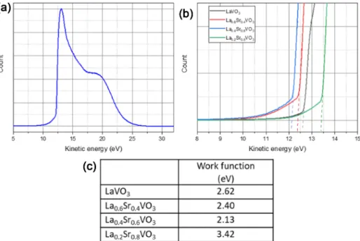
Work function of the LSVO samples were measured by ultraviolet photoemission spectroscopy (UPS). UPS results are presented in Fig. 7(a-b) and the work function
Fig. 7. (a) UPS spectrum of the La
0.4Sr
0.6VO
3sample; (b) The secondary electron cut-off levels of examined samples; (c) Work function
values of LSVO samples.
values, calculated from the formula: ϕ
LSVO= hν − (31.22
− KE
cutoff), are tabulated in Fig. 7(c).
It can be seen that the LaVO
3sample possesses a relatively low work function (2.62 eV). The work function decreases with the increasing Sr content. Particularly, the La
0.6Sr
0.4VO
3has a value of 2.40 eV, and the La
0.4Sr
0.6VO
3has the lowest value of 2.13 eV. Noticeably, the work function of La
0.2Sr
0.8VO
3increases to 3.64 eV, outweighing the value of the pure material. Sayer et al.
34)reported the work function value of La
0.3Sr
0.7VO
3at 2.40 eV, which lies between our values for x = 0.6 and x = 0.8. Thus, the present data is in good agreement with Sayer’s work.
Recently, the work function of La
2/3Sr
1/3VO
3film in contact with anatase TiO
2was recorded to be 5.01 eV,
22)which is much higher than our values. This may be due to the strong influence of the high work function TiO
2.
The dependence of work function value on the dopant content can be explained based on the structural transfor- mation with the participation of Sr dopant. The incorporation of Sr
2+in place of La
3+has two opposing effects. Due to the larger ionic radius of Sr
2+, the formation of Sr-O bonds increases the size of the surface dipole and reduces the work function. On the other hand, because of the lower valence state of Sr
2+, the substitution tends to depolarize the surface dipole, resulting in an increased work function. When the charge of La
3+still plays a role at low concentrations of Sr dopant, the former effect is expected to dominate, whereas the latter effect becomes more pronounced when much of La
3+is replaced by Sr
2+. The intrinsically low work function values of LSVO, especially of La
0.4Sr
0.6VO
3, could be essential for the material to be used in new applications. We assume that using La
0.4Sr
0.6VO
3instead of La
2/3Sr
1/3VO
3would improve the performance of p-LSVO/n-TiO
2Schottky diodes.
Also, the Schottky barrier height can be modulated by selecting the LSVO material with an appropriate work function. Furthermore, the LSVO material can be utilized in thermionic energy converters and vacuum cathodes for high power microwave sources. In addition, based on the influence of Sr addition on work function, we anticipate that the Ba-doped LaVO
3could also be a potential candidate for low work function material thanks to the larger ionic radius of the isovalent Ba
2+compared to Sr
2+.
4. Conclusion
In this study, well-dispersed and compositionally homogeneous LSVO NPs were synthesized successfully by a co-precipitation pathway. The co-precipitation route lowered the synthesis temperature to 700
oC and simplified the preparation steps. Regarding the morphology of the powders, the method not only decreased the particle
dimensions but also improved their structural and chemical uniformity. The compositional homogeneity of the synthesized LSVO NPs, verified by both SEM and TEM, is the first to be experimentally realized and reported. In addition, UPS measurements revealed the influence of Sr
2+substitution on LSVO’s work functions, with La
0.4Sr
0.6VO
3having the lowest value. Our work could pave the way for improved performance of existing applications as well as new potential utilization for the LSVO materials.
Acknowledgments
This work was supported by the Basic Research Laboratory Program through the Ministry of Education of the Republic of Korea (2019R1A4A1026125).
References
1. P. Dougier and A. Casalot, J. Solid State Chem., 2, 396 (1970).
2. P. Dougier and P. Hagenmuller, J. Solid State Chem., 15, 158 (1975).
3. M. Sayer, P. Chen, R. Fletcher and A. Mansingh, J. Phys.
C: Solid State Phys., 8, 2059 (1975).
4. J. B. Webb and M. Sayer, J. Phys. C: Solid State Phys., 9, 4151 (1976).
5. R. G. Egdell, M. R. Harrison, M. D. Hill, L. Porte and G. Wall, J. Phys. C: Solid State Phys., 17, 2889 (1984).
6. A. V. Mahajan, D. C. Johnston, D. R. Torgeson and F.
Borsa, Phys. Rev. B, 46, 10973 (1992).
7. F. Inaba, T. Arima, T. Ishikawa, T. Katsufuji and Y.
Tokura, Phys. Rev. B, 52, R2221 (1995).
8. S. Miyasaka, T. Okuda and Y. Tokura, Phys. Rev. Lett., 85, 5388 (2000).
9. I. C. Lekshmi, A. Gayen and M. S. Hegde, J. Phys.
Chem. Solids, 66, 1647 (2005).
10. J. Fujioka, S. Miyasaka and Y. Tokura, Phys. Rev. Lett., 97, 196401 (2006).
11. T. M. Dao, P. S. Mondal, Y. Takamura, E. Arenholz and J. Lee, Appl. Phys. Lett., 99, 112111 (2011).
12. C. Y. Liu, S. Y. Tsai, C. T. Ni and K. Z. Fung, J.
Electron. Mater., 46 2301 (2017).
13. L. Hu, R. Wei, J. Yan, D. Wang, X. Tang, X. Luo, W.
Song, J. Dai, X. Zhu, C. Zhang and Y. Sun, Adv.
Electron. Mater., 4, 1700476 (2018).
14. N. F. Mott, M. Pepper, S. Pollitt, R. H. Wallis and C. J.
Adkins, Proc. Math. Phys. Eng. Sci., 345, 169 (1975).
15. K. Tamm, P. Möller, G. Nurk and E. Lust, J. Electrochem.
Soc., 163, F586 (2016).
16. S. H. Song, S. E. Yoon, J. Choi, B. K. Kim and J. S.
Park, Int. J. Hydrogen Energy, 39 16534 (2014).
17. K. Tamm, R. Raudsepp, R. Kanarbik, P. Möller, G. Nurk and E. Lust, ECS Trans., 57, 1185 (2013).
18. J. S. Park, I. D. Hasson, M. D. Gross, C. Chen, J. M.
Vohs and R. J. Gorte, J. Power Sources, 196, 7488 (2011).
19. A. Parveen, N. K. Gaur and A. K. Nigam, AIP Conference Proc., 1536, 1137 (2013).
20. X. M. Ge and S. H. Chan, J. Electrochem. Soc., 156, B386 (2009).
21. C. Y. Liu, S. Y. Tsai, C. T. Ni and K. Z. Fung, J. Aust.
Ceram. Soc., 55, 97 (2019).
22. N. M. Vo and M. D. Gross, J. Electrochem. Soc., 159, B641 (2012).
23. D. H. Jung, Y. J. Oh, W. S. Park and H. Lee, Curr. Appl.
Phys., 20, 1453 (2020).
24. C. Y. Liu, S. Y. Tsai, C. T. Ni, K. Z. Fung and C. Y. Cho, Jpn. J. Appl. Phys., 58, SDDG03 (2019).
25. D. C. Crans, J. J. Smee, E. Gaidamauskas and L. Yang, Chem. Rev., 104, 849 (2004).
26. Y. Ma, X. Wang, S. Stopic, M. Wang, D. Kremer, H.
Wotruba and B. Friedrich, Metals, 8, 994 (2018).
27. J. Francavilla and N. D. Chasteen, Inorg. Chem., 14 2860 (1975).
28. A. Komura, M. Hayashi and H. Imanaga, Bull. Chem.
Soc. Jpn., 50, 2927 (1977).
29. M. M. Iannuzzi and P. H. Rieger, Inorg. Chem., 14, 2895 (1975).
30. H. T. S. Britton and G. Welford, J. Chem. Soc., 758 (1940).
31. J. Selbin, Chem. Rev., 65, 153 (1965).
32. G. A. Dean and J. F. Herringshaw, Talanta, 10, 793 (1963).
33. P. Patnaik, Handbook of inorganic chemicals, 1st ed., p.
887, McGraw-Hill, New York, USA (2002).
34. M. Sayer. U.S. Patent No. US3944866A (1974).