한국재난관리표준악회 논문집 2008년 6월
저11 권 저12호I pp. 61-66 £/;、 f! 극째납 E 흩|표즌획외
.원」/ Korean s。ciety。fScεietal Security
USN을 이용한 사면거동 탐지
장기태 · Albert Ho · 정천석 · 정 훈
SI。pe
Movement
Detecti。nusing Ubiquitous
Sens。r Netw。rk K.T. Chang*, Albert H。**, Chun-Suk Jung***, and H。。n Jung***접수일자 2008년 4월 30일/심사완료일 2008년 5월 29일
요 약 국토의 70% 이상이 산지로 구성되어 있어서 도로와 철도 건설을 위해 절토사면이 필연적으로 발생한다 우기, 동절기 서 리로 인한 지반융기, 그리고 해빙은 암석 탈락과 사면붕괴의 원인이 되며 매년 사면붕괴에 의한 차량파손과 인명피해가 증가하고 있다. 인명과 재산을 보호하기 위해 사연붕괴를 조기에 탐지할 수 있는 실시간 모니터링 시스템이 필요하다 GMG사에서 개발한 병진·회전·침하(TRS) 센서를 사면 내에 설치하여 실시간으로 사면을 모니터링을 할 수 있도록 했으나, 시스템의 데이터 획득체계가 취약하여 순간적인 낙뢰에 의해 전체 시스템이 손상될 수 있다 따라서 저자들은 USN(Ubiquitous Sensor Network)을 제시하여 낙뢰 에 의한 손상을 최소화시키고 신뢰도 높은 사면 변형 모니터링 체계를 구축했다
액심용어 절토사면, 실시간 모니터링 스시템, USN
ABSTRACT More than 70% of Korea consists of mountainous area and during the consπuction of roads and railroads many cut-slopes are inevitably formed. A number of environmental factors, such as the rainy season and frost heave during winter/thaw during spring, can result in rock falls and landslides. The failure of slopes is increasing every year and can cause damage to vehicles, personal l미 ury and even 옮tality. In order to help protect people and property, there is a need for real- time monitoring systems to detect the early stages of slope failures. In this respect, the GMG has been using Translation Rotation Settlement (TRS) sensor units installed on slopes to monitor movement in real-time. However, the data lines of this system are vulnerable and the whole system can be damaged by a single lightning strike. In order to overcome this, GMG have proposed the use of Ubiquitous Sensor Networks (USN). The adoption of a USN system in lieu of data cables can help to minimize the risk of lightning damage and improve the reliability of slope monitoring systems.
KEYWORDS cut-slopes, real-time monitoring system, USN
1. lntr。duction
Approximately 70% of Korea comprises mountainous terrain and a number of m갱or roads, highways and rail- roads, with associated slope cuttings, have been formed within these areas. The climatic conditions affecting these cut slopes include heavy precipitation between June to August, when most of the annual mean precipitation falls,
•p「。fess。「, Dept. 。f Civil Engineering, Kum。h Nati。nal Unive「sity
of Techn 。 logy, S/K。rea(E-mail: ktchang@kum。h.ac.kr)
**Ass。ciate Director, Ove Arup & Partne「S Hong K。ng Ltd
***University of Ulsan/Electrical Engineering, Ulsan, K。 rea
61
in addition to frost heave during winter and thaw during spring. Such conditions result in a high possibility for rock falls and landslides. According to statistics from the Minis- try of Consσuction & Transpoπation, there have been 326 recorded sites with rock falls or landslides in the past 7 years and this number is increasing annually. The above fail따es have caused damage to 45 C없s, 벼ured 9 people and resulted in 4 fatalities (Son, 2003).
To protect lives and property it is necess없y to have real- time monitoring systems which are capable of detecting the early stages of slope failures. In order to help achieve this,
the GMG have developed a Slope Maintenance System which is able to monitor slope behaviour in real-time. With their accumulated data and long term know-how, they have also derived a model to help predict the onset of the final stages of slope failure.
The Slope Maintenance System comprises a series of TRS sensor units and a data logger. The TRS sensors mea- sure the translation, rotation and settlement of the slope.
The data logger collects and saves the data from the sensors and sends the data regul때y to the monitoring database usmg CDMA communication modems (Han 뻐d Jang 2005; Woo and Jung, 2006).
As the sensors are connected to the data logger by cabled data lines, the system is vulnerable to lightning strikes and a single lightning strike could potentially damage the whole system. Given the mountainous terrain in which most of the monitoring slopes are located, the potential for lightning strikes is high.
In order to minimize the risk of lightning induced dam- age to the system, a wireless USN system has been adopted between the sensors and the data logger. The adopted USN mote is based on the IEEE 802.15.4 data transfer mecha- nism. Through the use of a wireless ad-hoc network sys- tem, the lightning’s effective range will diminish (Segen and Pingali, 1996; Masoud and Papanikolopuos, 2001;
Habit; Redwood) and the USN mote system will protect the remaining P없t of the system and ensure continuous moni- toring data is gathered for the slope.
2. MATHEMATICAL MODEL
The choice of an appropriate mathematical model is very important for the prediction of landslides. This is because fitting and prediction are totally different concepts. Fitting well means interpolation 뻐d estimation well. But it would be groun띠ess to extend such interpolation into future prac- tice. In order to achieve better prediction it is necess없y to
rrst understand the mechanisms and behaviour of landslide movement, including for example, line따ity tendency, peri- odical fluctuation, season transform, growing, and effi- ciently proved differential equations.
In order to achieve this, it is necessary to observe and analyse the real-time measured time series for actual fail-
효댁재난관리표준학회 논문집 제 1권제2호
25 20
Ol' -15 E lfJ 트
10 5
500
느릉재
1αXJ 1500 2000 2500
시간(h。ur)
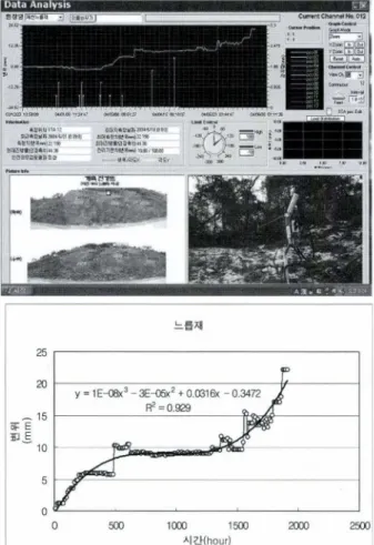
Fig. 1 Measured data and analyzed model of Nerupjae
ures and derive a reasonable mathematical model for the prediction of landslide initiation based upon these datasets.
In our experience of such works, the general failure charac- teristics of a landslide can be sub-divided into hνo main parts.
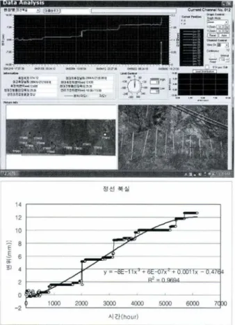
까1e rrst of these is the polynomial model (Straightfor- ward accelerated failure) as seen in Figure 1, whilst the sec- ond comprises a growth model, as presented in Figure 2.
Long-term real-time monitoring of slope displacεment
has been carried out using TRS sensor units installed on slopes at Nerupjae and B따sil, using the sensor unit config- uration shown in Figure 3. Each TRS sensor unit incorpo- rates four sensors, including two clinometers, one inclinometer and one tension wire. The nνo clinometers measure the tilt movement of along the X, Y 없is, effec- tively acting as a bi-axial tiltmeter, the inclinometer mea- sures the tilt along the Z axis and the tension wire is used to calculate the movement of the sensor unit relative to the ini- tial position of the sensor. Based on 뻐alysis of the above
USN을 이용한 사면거동 탐지 63
14
12
10
;::: 8
E
-E 6
Cl' lfJ 4
2 0
정선북실
1αm 2αm 3αm 4000 5000 6000 7000
시간(h。ur)
Fig. 2. Measured data and analyzed model 。fBuksil.
Fig. 3. TRS (Translation Rotati。nSettlement) sens。runit
data from a number of sensors along the slope profile, the overall movement of the slope can be analysed.
3. SYSTEM CONFIGURATION
Figure 4 shows the configuration of the entire real-time monitoring system. This system includes the database server, CDMA communication modems, the data logger,
Serve「Computer
←一 월
CDMA
c。mmunicati。n
Sensor Netw。rk
월를·→흩를
←--*를·를룰
I∼
뭘.뭘.
l
뿔.Fig. 4. Entire System Configuration
and the monitoring sensor networks, which comprise the USN modules and the TRS sensors.
The USN module receives the data from the TRS sensors and establishes an ad-hoc or mesh network by itself. The USN module then converts analog data to digital data using its 바1erent AID converter. Data is transmitted from one USN module to another until it reaches the ID zero USN module, where it is then saved to the data logger. Data from the entire sensor network is saved every minute and the data logger uses CDMA communication to transmit data pack- ages to the main server. The server then sorts the data by the slope’s name, analyses it and uploads the results to the respective slopes webpage. This enables checking of the slopes behaviour in real-time, provided that the Engineer has internet accessibility.
The USN module comprises a TIP 810CM platform that can utilize various sensors and realize sensor network appli- cation as a device node to compose sensor network to 正EE
802.15.4 based on TinyOS. TIP810CM offers a number of rntegrated user frequencies in the 2.4 GHz band. It also sup- ports ultra low power, Multi-hop network with IEEE 802.15.4 and is based on the TinyOS (TIP810CM).
Figure 5 shows a block diagram of the TIP8 l OCM.
This has MSP430 which uses very low current consump- tion and has 7 AID converter with 12 bit resolution (MSP430). This facilitates the use of many sensors with high resolution ability, which is an essential function given that slope displacement can sometimes be very slow. With CC2420, TIP810CM uses the 2.4 GHz and forms the multi-hop or Ad hoc network themselves.
‘bαnal of The Korean Society of Societal Secunty, Vol. 1, No. 2
MSI'·ιIOF1111 16어 Mier야om에.
Fig. 5. Block diag 「am of the TIP810CM.
바.,아~Jixim
I 6 I 1
~
...
r~ fdO d~
I
뺑I
~ |뾰|율Ox11 Ol08 야@ ; 짜F I o.;; 겨.JD ll<lE I lllOO Des빼liin
110'.'Ei I I 1s I
”
-』3띄뜨-
훌
|
. . . 얘|
뼈l 땐뼈 I lllOO깅 |때
”
| | 뼈 δ 그한m 뼈 u : 뼈 v I~c
용 t뾰-”
}‘ a""'""*) s...,1 JI l6 lill<6D ll<~ 이에 @μ
Fig. 6. Data packet format (USN to USN)
CC2420 uses DSSS (Direct Sequence Spread Spectrum) transceiver and 0-QPSK modulation. It can transmit 250 kbytes per second at maximum (CC2420).
The data format used is presented in Figure 6, which shows the data structure from USN mote to USN mote. The mote uses the RF power with 10 mW. Field testing of the mote’s communication reliability identified a maximum reliable communication r뻐ge in LOS (Line-of-Sight) of approximately 70 m.
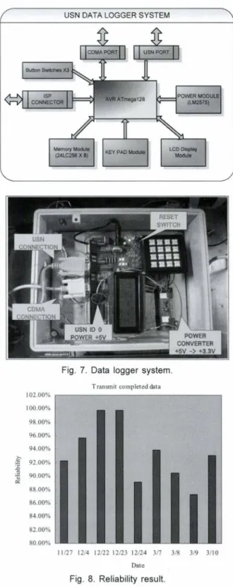
The data logger incorporates the USN module, Real- time clock (DS12C887), Serial EEPROM (24LC256*8), LCD module, key pad module, and CDMA communi- cation modem with micro-controller (Atmegal28). As shown in Figure 7, the main micro-controller in the data logger is Atmegal28, which was programmed to manage the whole system and perform the various tasks as shown below.
흔F국재난관리표준학회 논문집 제 1권 제2호
USN DATA L。GGERSYSTEM
Fig. 7. Data logger system.
Transmit completed data
I 02.00%
100.00%
98.00% 96.00%
94.00%
ξ 92.00%
i」공~ 90.00%
88.00%
86.00% 84.00% 82.00%
80.00%
11121 1214 12122 12123 12124 Jn 318 319 311 o Date
Fig. 8. Reliability result
The ID zero USN module in the data logger receives data from the other USN modules at one minute intervals using the RS-232C interface. When the data from every USN module has been received, it is saved in the Serial EEPROM with the date and time as its name (2008_03_10_11_23) in ASCII code. The data format is shown in Figure 8. The micro-controller changes the data format from the format
USN을 이용한 사면거동 탐지 65
shown in Figure 6 to that indicated in Figure 8.
The status of the data logger is displayed in the LCD and data packages are sent from the host server between the modems by using CDMA communication at a fixed time interval (every 10 minute). CRC (Cyclic redundancy checks)
Sσearn Data Error Check Method is used to check for any
eπors rn the data packages received. The algorithm for the data format change and CDl\ιA communication is pre- sented below:
3JI II usmo R«oi”r ‘•'"""'''~""'"""
331 iι .. ....,t 1usuro_oxc1 wid""'"-"-‘’,, ..
‘.,
ll21 lD '" ' --“”·‘·ι.,
334,.,, ... _‘'"-''…‘∞, """"'-‘'"-'"'''~' //쭈~ill의 ,I에등 ,,양껴f서 <I ~E/f •le! .예· /!~;/U n; n‘tu.1•UCSlOl;
Di"'''"'"·
mu""‘” ‘ ‘’'"'""-"뼈 | ,ω”-""''"'ι떼'"'""'"
DI I
lll r‘-“”""”-”_ ... ,, .... .,
J«I ‘l l”” -- -‘uO••RXBtrffllSIZIO’ ” • ‘""'"'·
341 “ “”‘ '~ιuOulXBUJ’llSIZIOl - -343 | "'-"'얘,
. ‘ "
h”
er OTtrtlowO•l,% ’-
-
341 뼈,.
///////////////////////// Cα” DA..TIRIC'rzm 3'91’
li) #d•f~/lllTZlfGC!I:
훌1 #Ucfme WA1111'fG CC뻐m
:i;1 ""'""'WAIT!κ ll.II.I
E ""'“% /fOCARRIIR
g ’/
Iii ,,,_,,,. • .., .. ,!),
?ii II '"-"'"fl'"'1nκ'."" ),
'1ilml<>l""'°""CDIUJ 3!il I
El ,_,때”001
:Ill I
~ ‘’(Ci cuα flahtr••O)if써씨 .. ‘0‘)CICHICK ----…,
Ji2
‘
llCE 떼-luabtr n l’
J;:l '" ' " ' ” ’"'
J;4 I
]!; C>Kl C-•~•~ Srnw • lι
JO "'""' .... '"' ‘ ’mm om,
"£/ aαJO:liabcr•O;
J;8 ,,ι'""'",‘”
J;lj "'-'""’‘"CH!’lZ9 OK "),
Jiii J
l1l Jbmk;
l11 ,_co뻐ICTIJlllCIDJ
ll3 I
p
‘
UICH CHIα ''"'"' "Olilldm •• 'O'ICH αIα Rι'"” ,//olu""""""'아π"31'; UICHCBIα 11\abu n l )U(dat‘ ·· ‘ l')CRC!llα lh.alhtrH,//tlH0/00α κ,.,,.π0, Iκ if(CHCRIα ll"Ullbtr .. 2)
'Jl1 UI‘.at••• ’B‘l
3111 I
319 OCSW•O>얘.
JI) .,, ... ”-
:ii U<SIIC•O>O
‘
JJ1 llHllB•O>OO,
El '"'"' ..
"”
l1<
4. SYSTEM EVALUATION & TEST
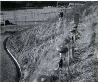
To confirm the formation of the system’s ad-hoc or mesh network and evaluate the overall performance of the sys- tem, a full scale field test was carried out at Gumi, with the test system installed within GMG’s test bed. The test bed comprises a 40 degree slope with an area in the order of30 m2.
The installed system components consisted of a data log-
geι four TRS sensor modules, the CD!\ι4 communication modems and the seπer computer. The TRS sensor units were mounted on piles which were drilled to 10 m depth and at 7 m spacing from each other. The TRS sensor mod-
Fig. 9. The system in the test bed 。fGMG.
ules were completely sealed withjn 뻐 alumiillum case and the data logger and CDMA comrnurucation module were also housed within weather proof enclosures. Figure 9 shows the general layout of the system installed in the test bed.
In order to analyze the system’s reliability, more than I 0,000 data packages were collected from the server com- puter and data logger. The retrieved data indicates that the USN motes successfully developed an ad-hoc or mesh net- work.
The overall reliabil따 of the system, in terms of the prob- ability of successful σansmission of data from the server computer to the web server, is presented in Figure 8. The results indicate the reliabil 때 to V없y between 87% and I 00%, with an average successful data transmission fre- quency 93% of the time.
5. CONCLUSION
This paper presents details of a real-time slope monitor- ing system fitted with a Ubiquitous Sensor Network. The system has been field tested and the res비ts examined to check the reliability of the system. During in the course of the field test it was found that the ad-hoc or mesh networks between the various nodes were well fonned and that data was transferred between them with a rugh degree of reliabil- ity. Additionally, whilst data transfer between the seπer
computer and web server was not seamless, the overall sys- tem performance was good enough for use as a real-time slope monitoring system.
bαnal of The Korean Society of Societal Secuity, Vd. 1, No. 2
The discussed system has now been in operation for more than 4 months and, based upon the evaluation of the results received, the real-time slope monitoring system with USN can monitor slopes with minimal risk of h맹tning damage.
This work was suppoπ.ed by 2008 Research Fund of GMG corporation.
REFERENCES
Son J. (2003) Installation 뻐d operation of real-time monitoring system for Landslide-prone slopes, Road maintenance Divi- sion Ministry of Consσuction & Transportation.
Han, H.-S., Jang, K.-T. (2005) Predicting the failure of slope by mathematical model, Journal Of The Korean Geotechnical Society, 21(2), pp.145-150.
Woo, J.-W., Jung, C. (2006) Design of a CDMA-based real-time
효F국재난관리표준학회 논문집 제 1권 제2호
remote monitoring system, Journal of The Institute of Elec- tronics Engineers of Korea, 43(1 ), pp.7-11.
Segen, J., Pingali, S. (1996) A camera-based system for σacking
people in real time. IEEE Proc. Of Int. Conj Paπern Recog- nition. 3, 63-67.
Masoud, 0., Papanikolopoulos, N. P. (2001) A novel method for tracking and counting pedestrians in real time using a single camera. IEEE Trans. on Vehicular Tech. 50, 1267-1278.
Habit monitoring on Great Duck Island, http://www.greatduck- island.net.
Redwood rese앙ch, http://ib.berkeley.edu/labs/dawson/research _ redwood.php.
TIP8 l OCM Datasheet, http://www.maxfor.co.kr/sub5 _ 2 _ l .htn디.
MSP43ιDatasheet, http;νwww.focus.ti.com/lit/ds/symlink/msp
430fll0la.pdf.
CC2420 Datasheet, http://www.focus.ti.com/docs/prod/folders/
print/cc2420.때f