미세접촉인쇄기법의 설계와 다중스케일해석
김정엽† · 김재현* · 최병익**
Design and Multi-scale Analysis of Micro Contact Printing
Jung-Yup Kim, Jae-Hyun Kim, Byung-Ik Choi
Key Words : Finite element method(유한요소법), Micro contact printing(미세접촉인쇄기법), Multi- scale analysis(다중스케일해석), Slip-link model(슬립링크모델)
Abstract
Nanometer-sized structures are being applied to many fields including micro/nano electronics, optoelectronics, quantum computing, biosensors, etc. Micro contact printing is one of the most promising methods for manufacturing the nanometer-sized structures. The crucial element for the micro contact printing is the nano-resolution printing technique using polymeric stamps. In this study, a multi-scale analysis scheme for simulating the micro contact printing process is proposed and some useful analysis results are presented.
Using the slip-link model [1], the dependency of viscoelasticity on molecular weight of polymer stamp is predicted. Deformation behaviors of polymeric stamps are analyzed using finite element method based upon the predicted viscoelastic properties.
1. 서 론
최근 전자기술의 빠른 발전으로 인하여 나노 미터 크기의 패턴을 제작할수 있는 공정기술의 필요성이 크게 증가하고 있다. 이러한 공정기술 은 전자소자, 바이오센서, 양자컴퓨터소자, 광전 자소자등 여러곳에 필요하다. 무어의 법칙에 의 하면 전자소자의 크기는 수년내에 수십나노미터 의 크기로 줄어들 것이다. 기존의 리소그래피기 술은 0.1μm 가 기술적 한계로 알려져있다. 이러 한 0.1μm 이상의 패턴을 구현할수 있는 기술로 는 X 선 리소그래피, 이온빔 리소그래피와 같은 것이 있으나 비용이 많이 들고 양산에 문제점이 있다. 선폭문제, 비용, 양산성을 모두 만족시키는 방법으로 나노임프린트(nano imprint)가 있다. 이 러한 방법은 전자빔 리소그래피나 X 선 리소그래
피를 이용하여 패턴이 가공된 마스터(master)를 만들고 만들어진 마스터를 직접 이용하거나 몰드 (mold)를 만들어서 원하는 나노패턴을 인쇄한다.
인쇄된 패턴은 식각과정을 통하여 마스터와 동일 한 패턴을 제작할 수 있다. 나노임프린트기술에 서 사용하는 폴리머는 기계적, 광적, 전기적 물성 이 아주 우수하다. 좋은 해상도(resolution)와 대 비도(contrast)를 얻기위해서는 적절하게 폴리머요 소를 설계하여야 한다. 나노임프린트 기술은 여 러가지가 있으며 핫엠보싱(hot embossing), 몰드어 시스티드 리소그래피(mold-assisted lithography), 미 세접촉인쇄기법(micro contact printing)과 같이 크 게 3 가지로 나뉠 수 있다. 핫엠보싱은 1995 년에 Chou[4]에 의해 소개되었으며 고온 고압의 환경 에서 마스터를 직접 눌러서 폴리머에 패턴을 만 드는 방법이다. 몰드어시스티드 리소그래피는 1996 년 haisma[5]에 의해 제안되었으며 여기에서 는 UV curing 을 사용하며 비교적 저온 저압의 환 경이다. 미세접촉인쇄기법은 1993 년 Kumar 와 Whitesides 에 의해 소개되었으며 폴리머 스탬프 를 사용하며 SAM(Self Assembled Monolayer)을 만 든다. 본 연구에서는 이들 방법중 미세접촉인쇄
† 한국기계연구원 마이크로응용역학그룹 E-mail : [email protected]
TEL : (042)868-7889 FAX : (042)868-7884 * 한국기계연구원 마이크로응용역학그룹
** 한국기계연구원 마이크로응용역학그룹
기법에만 관심을 두었다. 즉, 미세접촉인쇄기법 에 사용되는 스탬프의 해석을 위하여 연속체 길 이스케일(continuum length scale)과 폴리머체인 길 이스케일(polymer chain length scale)을 연결하는 다 중스케일해석(multi scale analysis)을 하였으며 이를 통하여 폴리머 스탬프 설계에 기여하고자 하였다.
2. 미세접촉인쇄기법
2.1 개 요
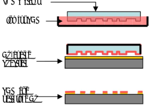
미세접촉인쇄기법(micro contact printing)의 특징 은 대면적이고 평탄하지 않은 substrate 에 적용가 능하다는 것이다. 여기에서는 폴리머 스탬프를 이 용하여 substrate 위에 SAM 을 만든다. Fig. 1 에 미 세접촉인쇄기법의 공정도를 나타내었다. 스탬프에 침수를 통하여 잉크를 묻히고 이것을 금이 코팅된 substrate 에 놓고 가압한다. 이렇게 하면 잉크는 몇초안에 두께 1-3nm 의 SAM 을 형성하게 되고 이것이 식각공정중에 보호막으로 작용하게 되어 원하는 패턴을 얻을 수 있게 된다.[3,6]
Fig. 1 Schematic of micro-contact printing;
(a) immersing stamp into ink, (b) pressing stamp on Au-coated substrate, (c) utilizing SAM as an etch mask of Au.
2.2 미세접촉인쇄에서의 문제점과 해석이슈 미세접촉인쇄기법에서는 폴리머 스탬프를 사용 하기에 폴리머가 갖는 장단점을 그대로 가지고 있 다. 강성이 낮고 유연성이 좋은 반면 그 거동이 비선형이며 점탄성의 성질을 갖고 있고 종횡비 (aspect ratio)를 크게 할 수 없는 단점이 있다[3].
폴리머 스탬프는 다른 요소와는 달리 직접적으 로 패턴형성에 관여하기에 본 연구에서 집중적인 관심을 두었다. 보고된 폴리머 스탬프의 실패모드 는 다음과 같이 1) self-adhesion, 2) collapse, 3) blur (or roundedness) 4) sagging 이다. Self-adhesion 은 adhesion force 에 의해 인접한 스탬프의 패턴이 달 라붙어 원하는 패턴이 형성되지 않는 현상이다.
이것은 폴리머의 탄성계수, 표면에너지, 종횡비,
거리와 관계가 있다. Collapse 는 높은 종횡비를 가 진 패턴이 가해진 압력 또는 자중을 받을 때 생긴 다. Blur(or roundedness)는 낮은 종횡비를 가진 패턴 에서 종종 발견되며 이는 표면장력 때문에 생긴다.
Sagging 은 패턴사이의 거리가 클 때 나타나며 결 국 원하지 않는 패턴을 형성하게 된다.
이러한 문제를 해결하기 위해서는 폴리머 스탬 프의 변형을 해석하고 낮은 선폭을 가진 패턴에 대한 설계지침을 만들어야 한다. 폴리머 스탬프의 기계적성질은 폴리머의 분자량조절, 보강재, 이종 재료사용등으로 바뀔수 있다. 본 연구에서는 다양 한 분자량을 가진 PDMS (polydimethylsiloxane) 스 탬프의 점탄성 거동을 예측하고 또 다양한 기하학 적형상과 하중조건에서 스탬프의 변형을 계산하고 자 한다.
Fig. 2 Failures of polymeric stamps
3. 시뮬레이션모델 및 다중스케일해석
폴리머 스탬프의 해석을 위해서 두가지의 서로 다른 시뮬레이션 모델이 사용되었다. 폴리머 재료 의 점탄성특성을 예측하기위하여 Takimoto 등의 슬립링크모델(slip-link model)을 사용하였다[1]. 그 리고 여기서 계산된 폴리머의 점탄성결과를 가지 고 유한요소모델을 이용하여 폴리머 스탬프의 변 형과 응력을 계산하였다. 이러한 두가지 시뮬레이 션 모델은 스케일과 적용이론 측면에서 다르지만 본 해석에서는 서로 연결되었다.
3.1 시뮬레이션 모델
폴리머 스탬프의 해석을 위해서 Takimoto 등의 슬립링크모델(slip-link model)을 사용하였다[1]. 슬 립링크모델은 기존의 튜브모델(tube model)[7]을 확 장하여 통계적 방법(stochastic simulation method)을 적용시킨 것이다. 슬립링크모델에 관한 자세한 내용은 [1,5]에 나와있으며 여기에서는 간략한 소 개만을 기술한다.
슬립링크모델에서는 폴리머체인이 primitive path (a) Self-adhesion (b) Collapse
(c) Blur (or roundedness) (d) Sagging PDMS Stamp
Ink for SAM
Au-coated Substrate
SAM and patterned Au
와 slip-link 에 의해서 표현된다. 모델은 무수히 많 은 체인으로 구성되어 있으며 slip-link 에 의해 서 로 연결되어 있다. 통계적 시뮬레이션의 매 스텝 마다 다음의 4 가지 사항이 고려된다. 1) 모든 primitive path 는 시스템의 거시적 변형에 따라 똑 같이 변형된다. 2) primitive path 의 길이는 Langevin Eq.에 따라서 계산된다. 3) 각 primitive path 는 확 산에 의해 랜덤하게 움직인다. 4) 3 의 결과로서 slip-link 는 primitive path 의 움직임에 따라 생성되 거나 없어진다.
연속체방정식을 풀기 위하여 유한요소법을 사 용하였다. 유한요소모델은 4 절점 평면변형요소로 구성되었다. 해석시에는 대변형성과 비선형성을 고려하였으며 점탄성변형 또한 고려하였다. Fig. 4 에 보인 것처럼 자체접촉(self-contact)을 반드시 고 려하여야 올바른 결과를 얻을 수 있기에 자체접촉 (self-contact) 조건을 폴리머 스탬프에 주었다.
Fig. 3 (a) Entangled linear polymer chains (b) slip-link model [4]
Fig. 4 Mesh distortion and interpenetration during finite element analysis
3.2 다중스케일해석
두 가지의 다른 스케일의 해석이 수행되었다.
하나는 폴리머체인 길이스케일(polymer chain length scale)이며 슬립링크모델(slip-link model)에 의해 고 려 되었다. 슬립링크모델을 이용하여 폴리머재료 의 점탄성 특성을 계산하였다. 다른 하나는 연속 체 길이스케일(continuum length scale)이다. 여기에 서는 연속체역학이 적용되는데 보통 연속체역학은
수십나노미터의 크기까지는 적용가능한 것으로 알 려져 있다. 본 연구에서는 유한요소해석을 이용 하여 폴리머 스탬프의 응력과 변형을 계산하였다.
폴리머의 점탄성 특성은 작용된 변형률(strain)과 변형률속도(strain rate)에 따라 달라지므로 유한요 소해석의 결과에 따라 슬립링크모델의 변수를 바 꿔 주어야 한다. 결국 두가지 시뮬레이션 모델을 반복적으로 적용(iteration)하여 자기일치성(self- consistency)을 가지도록 한다.
Fig. 5 Multi-scale analysis scheme for polymeric stamp
4. 해석결과
폴리머 체인의 기계적 거동을 시뮬레이션하기 위하여 슬립링크모델을 기반으로 하여 통계적 계 산을 수행하는 PASTA[5]를 사용하였다. 그리고 유 한요소해석을 위해서는 상용코드[11]를 사용하였 다. 이 코드는 contact 및 비선형해석에 뛰어난 성 능을 가지고 있다. 스탬프의 재료는 다른 논문 [3,4,10,12]에서와 같이 PDMS 를 사용하였다.
4.1 완화계수(Relaxation Modulus)
-2 0 2 4 6 8 10 12 14 16 18 20 22
-0.2 0.0 0.2 0.4 0.6 0.8 1.0 1.2 1.4 1.6
Mw = 47600 g/mol Mw = 95200 g/mol Mw = 190400 g/mol Mw = 285600 g/mol
Shear Relaxation Modulus (MPa)
Time(Sec)
Fig. 6 Dependency of relaxation modulus Slip-link model:
Viscoelastic property Glass plate
Substrate
Polymer Imprinting
M
Constitutive equation FEM:
deformation analysis
Simulation parameter
Severe mesh distortion and interpenetration of surfaces Substrate
Polymeric Imprinting
on molecular weight
PDMS 의 기계적 성질은 분자량(molecular weight), cross link functionality, 첨가재(filler content) 와 같은 여러가지 요소에 의해 바뀐다. 여기에서 는 분자량만을 고려하기로 한다. 슬립링크모델의 계산을 위하여 3 가지 파라미터가 필요하다. 필요 한 3 가지 파라미터는 M (entanglement molecular e weight), τe (Rouse relaxation time), G (shear N plateau modulus)이다. PDMS 스탬프의 계산을 위 하여 사용된 파라미터의 값은 Me =4760g/mol ,
sec 10 1 . 2 × −3
e =
τ , MPaGN =1.0 이다. Fig. 6 에 PDMS 의 relaxation modulus 결과를 나타내었다. (여 기에서 PDMS 체인의 수는 10,000 이고 stress relaxation behavior 을 얻기위해서 적용한 전단변형 률은 0.1 이다.) 전단변형률 (shear strain)에 따라 relaxation modulus 의 값은 변한다. 분자량(molecular weight)이 190,400g/mol 일 때 전단변형률 이 0.5 보 다 작으면 relaxation modulus 는 일정하다. 그러나 전단변형률 이 0.5 보다 크면 relaxation modulus 는 변한다. 또한 분자량이 95200g/mol 이면 relaxation modulus 이 변하는 전단변형률 의 값은 0.2 이다.
4.2 PDMS 의 단축반복변형
미세접촉인쇄기법에 사용되는 스탬프는 일단 제작이 되고 나면 반복적으로 사용하게 되며 사이 클릭 하중(repetitive pressing and detaching load)을 받 게 된다. 그러므로 슬립링크모델을 이용하여 Fig.
7 에서와 같은 히스테리시스 거동을 계산하였다 (체인수 1000).
-0.6 -0.4 -0.2 0.0 0.2 0.4 0.6
-1.2 -0.8 -0.4 0.0 0.4 0.8 1.2
1.6 1st pressing 1st detaching 2nd pressing 2nd detaching 3rd pressing 3rd detaching 4th pressing 4th detaching 5th pressing 5th detaching
Mw = 190400 g/mol Strain rate = 0.0238 sec-1
Stress (MPa)
Strain
Fig. 7 Uniaxial cyclic loading behavior of PDMS
4.3 FEM 을 이용한 임계압력예측
0.1 0.2 0.3 0.4 0.5
0.0 0.1 0.2 0.3 0.4 0.5 0.6
a
b c
Nano patterns a
b c
Nano patterns
Critical Pressure(MPa)
Fill Factor (b/c) Elastic (Aspect Ratio(a/b) = 1) Visco (Aspect Ratio(a/b) = 1) Elastic (Aspect Ratio(a/b) = 0.5) Visco (Aspect Ratio(a/b) = 0.5)
0.4 0.6 0.8 1.0 1.2 1.4 1.6
0.00 0.05 0.10 0.15 0.20 0.25 0.30 0.35 0.40
a
b c
Nano patterns a
b c
Nano patterns
Critical Pressure(MPa)
Aspect Ratio (a/b) Elastic(Fill Factor(b/c) =0.25) Visco(Fill Factor(b/c) =0.25) Elastic(Fill Factor(b/c) =0.125) Visco(Fill Factor(b/c) =0.125)
Fig. 8 (a) Critical pressure vs. fill factor, (b) critical pressure vs. aspect ratio obtain by elastic and viscoelastic FEA(Finite Element Analysis) Fig. 1 에 설명한 것처럼 PDMS 스탬프는 나노 패턴을 전사시키기 위하여 금으로 코팅된 모재 (substrate)에 밀착시킨다. 스탬프의 변형을 계산하 기 위하여 유한요소해석을 통하여 탄성해석과 점 탄성해석을 모두 수행하였다. 해석에서 사용한 PDMS 의 분자량은 95200g/mol 이며 패턴너비(b)를 100nm 로 고정시키었다. 탄성해석에서는 plateau modulus 를 사용하였다. 점탄성해석에서는 폴리머 스탬프가 1 초동안 가압된 것으로 가정하였다. 많 은 공정 파라미터중에서 PDMS 스탬프의 압력에 주요 관심을 두었으며 임계압력(critical pressure)은 sagging 이 발생하는 압력으로 정의하였다. 그러므 로 미세접촉인쇄기법을 설계할 때 스탬프의 압력 은 임계압력보다 작아야 한다. 만약 압력이 임계 압력보다 높으면 원하는 패턴을 얻을 수 없게 된 다.
5. 결 론
슬립링크모델(slip-link model)과 연속체모델 (continuum model)을 사용하는 다중스케일해석이 제안되었다. 폴리머체인 길이 스케일(polymer chain length scale)에서 적용되는 슬립링크모델을 사용하
여 점탄성특성이 계산되었으며 연속체해석을 수행 하는 유한요소법에 의해 폴리머 스탬프의 응력과 변형이 계산되었다. 얻어진 결과는 재료선정과 스 탬프압력, 스탬프 시간, 패턴의 크기와 같은 공정 변수 결정에 사용될 수 있다.
후 기
본 논문은 21 세기 프론티어 연구개발사업인 나노메카트로닉스 기술개발사업단의 연구비 지원 (02-K14-01-012-3-0)에 의해 수행되었습니다.
참고문헌
(1) J. Takimoto, H. Tasaki, and M. Doi, 2000,“Predictions of the rheological properties of polymer melts by stochastic simulation,” XIIIth International Congress on Rheology, p. 97.
(2) NTSC, 2000,“National nanotechnology initiative,” . (3) H.-C. Scheer, H. Schulz, T. Hoffmann, and C. M.
Sotomayor Torres, 2002, “Nanoimprint techniques,” in Handbook of thin film materials Vol. 5 edited by H. S.
Nalwa: Academic press, pp. 1-60.
(4) S. Y. Chou, P.R. Krauss, and P. J. Renstrom, 1995,
“Imprint of sub-25nm vias and trenches in polymers,”
Applied Physics Letter Vol. 67, pp. 3114-3116.
(5) User’s manual of PASTA, http://octa.jp.
(6) A. Kumar and G. M. Whitesides, 1993,“Features of gold having micrometer to centimeter dimensions can be formed through a combination of stamping with an elastomeric stamp and an alkanethiol “ink” followed by chemical etching,” Appl. Phys. Lett. Vol. 63, pp.
2002-2004.
(7) M. Doi and S. F. Edwards, 1986, The theory of polymer dynamics, Oxford University Press.
(8) R. W. Jaszewski, H. Schift, J. Gobrecht, and P.
Smith, 1998, “Hot embossing in polymers as a direct way to pattern resist,” Microelectron. Eng. Vol. 41/42, pp. 575-578.
(9) J. Haisma, M. Verheijen, K. Van den Heuvel, and J.
Van den Berg, 1996, “Mold-assisted nanolithography:
A process for reliable pattern replication,” J. Vac. Sci.
Technol. Vol. B14, pp. 4124-4128.
(10) B. Michel, A. Bernard, A. Bietsch, E. Delamarche, M. Geissler, D. Juncker, H. Kind, J.-P. Renault, H.
Rothuizen, H. Schmid, P. Schmidt-Winkel, R. Stutz, and H. Wolf, 2001, “Printing meets lithography: Soft approaches to high-resolution patterning,” IBM Journal of Research and Development 45, pp. 697-719.
(11) User’s manual of ABAQUS
(12) H. Schmid and B. Michel, 2000, “Siloxane polymers for high-resolution, high-accuracy soft lithography,”
Macromolecules Vol. 33, pp. 3042-3049.
(13) E. Delamarche, H. Schmid, B. Michel, and H.
Biebuyck, 1997, “Stability of molded polydimethyl-
siloxane microstructures, ” Adv. Mater. Vol. 9, pp. 741- 746.