DOI: http://dx.doi.org/10.4313/JKEM.2016.29.2.125 ISSN 1226-7945 (Print), 2288-3258 (Online)
레일 체결구 결함 검측 모듈의 방열성능 개선을 위한 열 해석
채원규1, 박영2, 권삼영2, 이재형1,a
1 성균관대학교 전자전기공학부
2 한국철도기술연구원
Thermal Analysis for Improvement of Heat Dissipation Performance of the Rail Anchoring Failure Detection Module
Won kyu Chae1, Young Park2, Sam young Kwan2, and Jaehyeong Lee1,a
1 Department of Electronic Electrical & Computer Engineering, Sungkyunkwan University, Suwon 16419, Korea
2 Institute of Korea Railroad Research, Uiwang 16105, Korea
(Received October 27, 2015; Revised December 28, 2015; Accepted January 24, 2016)
Abstract : In this paper, various heat dissipation designs for a rail anchoring failure detection module were investigated by a thermal flow analysis. For the detection module with the heat dissipation design on the overall housing surface, an average temperature inside the module was lowered by 25℃ when compared to no heat dissipation design. In addition, an internal heat-flow blocking layer and an heat conduction layer inserted between the LED module and housing case were effective in reducing the temperature in the rail anchoring failure detection, which has a limited space for installation and little air flow. Especially, the temperature near LED module decreased below 55℃ when the optimal heat dissipation design was applied.
Keywords: Rail anchoring measurement module, Heat flow simulation, Heat dissipation design, Heat conduction
1. 서 론
최근 우리나라에 경부선 및 호남선 수서발 고속철도 등 다양한 곳에서 고속철도가 건설되어 운행이 되고 있으며, 이에 따라 고속철도의 선로 유지 보수와 관련 하여 많은 관심을 받고 있다. 현재 우리나라의 경우, 운행시간이 종료되고 다음 날 첫차가 출발하기 직전까 지의 시간을 유지 보수 시간으로 운영 중인데, 선로 및 전차선의 관리를 위해서는 매우 부족한 시간이다.
현재 고속선 및 일반선의 경우, 야간에 사람이 직접
a. Corresponding author; [email protected]
Copyright ©2016 KIEEME. All rights reserved.
This is an Open-Access article distributed under the terms of the Creative Commons Attribution Non-Commercial License (http://creativecommons.org/licenses/by-nc/3.0) which permits unrestricted non-commercial use, distribution, and reproduction in any medium, provided the original work is properly cited.
육안으로 선로변의 상태를 확인하기 때문에 유지 보수 비용이나 시간이 많이 소요되고 있다 [1]. 또한 부분적 으로 EM-130 등의 궤도 검측 차량을 이용하여 선로 및 전차선의 고장유무를 조사하고 있으나, 이는 200 km/h 급 이하의 저속 구간에서의 사용이 가능한 차량 이며, 현재 운영 중인 고속선로에는 적합하지 않은 차 량임을 알 수 있다. 따라서 현재 고속철도 선로에 적 합한 300 km/h급 검측차량이 개발 중에 있다 [2].
개발 중인 고속 검측차량에는 궤도 틀림, 레일 마모, 레일 체결구 결함 탐지 등의 기능을 수행할 수 있는 다양한 검측모듈들이 탑재되게 된다 [3,4]. 이 가운데 레일 체결구 결함 검측 모듈(rail anchoring failure detection module)의 경우, 라인 스캔 카메라(line- scan camera)를 이용하여 선로 체결구를 고속으로 촬
다양한 부품들이 배치되게 된다. 그 결과, 고휘도 LED 모듈에서 발생되는 열이 검측모듈 내부의 다양한 센서 들의 동작에 영향을 미쳐 측정 오차가 발생하게 되고 [5,6], 일정 시간 이상 동작시 내부 온도 상승으로 검 측이 불가능하게 된다. 따라서 협소한 공간에 적용 가 능한 방열설계가 필요한데, 실제 시제품 제작 전 설계 된 방열 구조의 열 해석을 통해 검측 모듈 제작에 소 요되는 비용 및 시간을 줄일 수 있다 [7.8].
열해석의 경우 SolidWorks를 이용하여 실시하였다.
SolidWorks의 경우 열전도, 대류, 복사열 전달 등의 해석을 수행하며 등방성, 이방성, 온도 의존성 재질 속 성을 포함하고 있어 SolidWorks를 사용하여 열해석을 진행 하였다 [9].
본 논문에서는 다양한 방열 구조의 열 해석을 통해 레일 체결구 결함 검측 모듈에 적용 가능한 방열 구조 를 제시하였다. 이를 위해 검측 모듈 외부 하우징의 방열 구조, LED 부분에서 발생하는 열이 내부로 유입 되는 것을 막기 위한 차단막 구성, 마지막으로 LED 모듈의 열을 외부로 빠르게 전달하기 위한 검측 모듈 내부에서의 방열 구성 등으로 하여 추가적인 열해석을 진행하였다.
2. 실험 방법
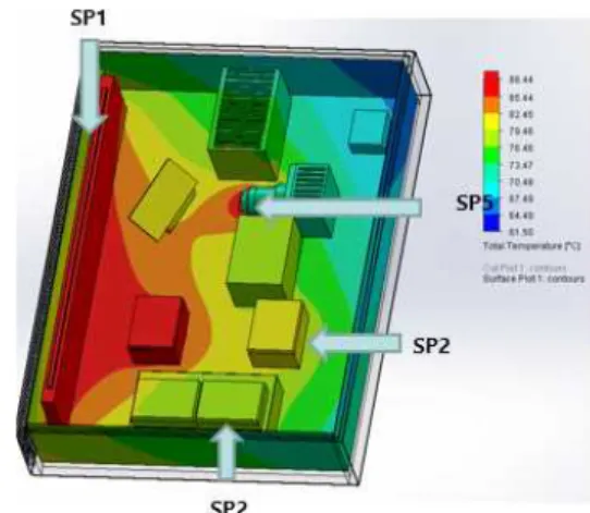
그림 1은 레일 체결구 결함 검측 모듈의 사진 및 열 화상 카메라를 이용하여 실제 동작시 온도 변화를 측 정한 것이다. 열차 하부의 자갈이나 다른 물체의 비산 (scattering)으로 인한 모듈의 파손을 막기 위해서 실 제로는 전체적인 하우징을 통해 모듈 내부를 밀폐시키 지만 열화상 카메라 측정을 위하여 상부의 하우징을 제거한 상태에서 온도분포를 측정하였다. 측정 시 외부 온도는 26℃, 검측 모듈 동작 시간은 40분을 설정하였 으며, 주변 공기의 유입이 있는 상태에서 검측 모듈 내부의 온도를 측정하였다. 따라서 하우징의 상부가 덮여 있는 경우 검측 모듈 내부의 온도는 더욱 높을 것으로 예상된다. 그림 1의 열화상 온도 데이터로부 터 검측 모듈 내부에 총 5개의 발열부(heat source)가
Fig. 1. Photograph of the rail anchoring failure detection module and its temperature distribution using infrared thermometer camera under operating condition.
Fig. 2. A simplified drawing of the rail anchoring failure detection module and heat distribution by thermal flow simulation.
존재함을 알 수 있다. 가장 온도가 높은 부위는 300 W LED 모듈 부분으로 40분 후 약 85℃까지 높아짐을 알 수 있었다. 또한 전체적인 검측 모듈 내부의 온도는 45℃ 이상임을 확인 하였다.
그림 2는 간략화된 검측 모듈 내부 도면 및 열 해석 결과를 나타낸 것이다. 열화상 카메라의 온도 분포 데 이터를 토대로 다섯 곳의 발열부를 지정하였고, 공기 유입이 없이 내외부가 차단된 상태를 가정하였다. 또한 내부 및 외부의 시작 온도는 20℃로 설정하였으며, 1 시간 동안의 열 해석을 진행하였다. 열 해석의 경우, 온도 분포가 중요하지만 검측 모듈 내부에서 외부로의 열 전도에 특성에 중점을 두고 수행하였다. 검측 모듈 내부의 온도 분포는 SP(Spot Point)1 지점(LED 모듈 에서 온도가 가장 높게 나타났으며, 다른 부분들도 그 림 1에서 열화상 카메라로 실제 측정한 결과와 유사하게
Fig. 3. A schematic of the rail anchoring failure detection module with heat dissipation design on the overall housing surface.
Fig. 4. A schematic of rail anchoring failure detection module with the internal heat-flow blocking layer.
나타났다. 그림 3은 검측 모듈 외부 하우징 전체에 방 열 설계한 구조를 나타낸 것이다. 검측 모듈 내부에서 발생하는 열을 빠르게 외부로 전달하여 내부의 온도를 낮출 수 있도록 LED 모듈 쪽에만 한정되어 있던 방열 부분을 하우징 전체로 확대하여 열 해석을 진행하였다.
측면의 경우, 이전 LED 모듈 부분의 방열구성과 동일 하게 하였고, 하부의 경우, 두께 변화 없이 heat sink 를 구성한 것과 15 mm 두께의 기존 모듈 외함에 추 가적으로 방열 구성을 한 두 가지의 조건으로 나누어 열 해석을 실시하였다.
그림 4는 LED 모듈에서 발생하는 열이 내부로 전달이 되는 것을 막기 위해 차단막을 설치한 검측 모듈 내부 구조를 나타낸 것이다. 이때 차단막은 내열성이 우수한 테플론(PTFE) 재질을 선택하여 열 해석을 수행하였다.
3. 결과 및 고찰
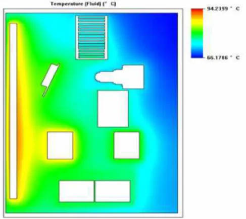
그림 5와 6은 별도의 방열 설계가 되어 있지 않은
Fig. 5. Temperature distribution in the rail anchoring failure detection module without heat dissipation design.
Fig. 6 Temperature profile of the rail anchoring failure detection module without heat dissipation design.
레일 체결구 결함 검측 모듈 내부의 온도 분포를 나 타낸 것이다. 이때 외부로부터의 공기 유입이 없는 조 건을 가정하여 열 해석을 수행하였다. 그림에서 LED 모듈에서 발생된 열이 모듈 내부로 전달되어 전체적으 로 온도가 상승하고 있음을 알 수 있다. 1시간 동안 열 해석을 진행한 결과, 검측 모듈 내부는 최대 66℃
까지 상승함을 확인할 수 있었다. 방열설계가 되어 있 지 않은 검측 모듈의 경우, 내부에서 외부로의 열 전 달이 잘 이루어지지 않아 LED 모듈 부분에서 발생한 열이 내부에 계속 머무르게 되고 이로 인하여 검측 모 듈의 성능 및 안전성을 문제가 될 것으로 생각된다.
그림 7 및 8은 두께 변화 없이 검측 모듈 외부 하우 징 전체에 방열 설계를 한 경우와 15 mm 두께의 기 존 모듈 케이스에 추가적으로 방열 구성을 한 경우의 내부 온도 분포를 나타낸 것이다. 그림에서 볼 수 있 듯이 하우징 두께 변화 없이 방열 설계하였을 경우, 오히려 열 전도가 잘 이루어지지 않아 검측 모듈 내부 의 온도가 119℃까지 상승하였다. 또한 전체적인 내부 온도도 67℃ 이상으로 상승하였음을 알 수 있다. 그러 나 기존 하우징 두께에 추가적으로 heat sink을 설치
Fig. 7. Temperature distribution in the rail anchoring failure detection module with heat dissipation design on the overall housing surface: (a) no housing thickness variation, (b) thicker housing case.
Fig. 8. Temperature profiles of the rail anchoring failure detection module with heat dissipation design on the overall housing surface: (a) no housing thickness variation, (b) thicker housing case.
한 경우, 내부 최고 온도는 69℃로 감소하였고, 최저 온도도 46℃로 검측 모듈 내부의 온도가 전체적으로 많이 내려갔음을 알 수 있다. 알루미늄과 같은 도체에 서의 열흐름율(rate of heat flow) 또는 열류(heat current)는 다음의 식으로 표현된다 [9].
′
(1)
여기서 는 온도구배(temperature gradient), A는 열 흐름 방향에 수직인 면적, 는 열 전도율(thermal conductivity), 는 열저항(thermal resistance)
Fig. 9. Temperature distribution in rail anchoring failure detection module with the internal heat-flow blocking layer.
Fig. 10. Temperature profile of rail anchoring failure detection module with the internal heat-flow blocking layer.
이다. 하우징 두께 변화 없이 방열 설계한 경우, 단면적 감소에 따른 열 저항 증가로 인해 검측 모듈 외부로의 열 전도가 잘 이루어지지 않아 내부 온도가 증가한다.
따라서 방열 설계시 heat sink뿐만 아니라 외부 하우 징 두께도 고려해야 함을 알 수 있다. 한편, 그림 8은 측면에서 바라본 검측모듈의 온도변화이다. 방열구성 전과 비교하여 방열 구성시 하부에서 열이 전달이 빠 르게 이루어지고 있음을 확인 할 수 있고 이로 인한 내부의 온도가 내려가고 있음을 확인할 수 있다.
그림 9와 10은 검측 모듈 내부에 차단막을 설치한 경우의 열 해석 결과를 나타낸 것이다. LED 부분에서 발생한 열이 차단막에 의해 검측 모듈 내부로 유입되 지 않고 하부 방열구조를 통하여 외부로 열이 전달이 되면서 검측 모듈 내부의 전체적인 온도가 내려감을 알 수 있다. 차단막 설치 전 최저 및 최고 온도는 각 각 46.5℃와 69.03℃이었으나 차단막 설치 후 42.1℃
및 63.98℃로 감소하였다. 그러나 그림에서와 같이
Fig. 11. Temperature distribution in rail anchoring failure detection module with the internal heat-flow blocking layer and heat conduction layer inserted between the LED module and housing case.
Fig. 12. Temperature profile of the rail anchoring failure detection module with the internal heat-flow blocking layer and heat conduction layer inserted between the LED module and housing case.
LED 모듈 쪽의 차단막으로 생긴 공간의 경우, 오히려 온도가 상승함을 볼 수 있다. 이러한 문제점을 해결하 기 위해 LED 모듈과 LED 모듈 측 하우징 외벽 사이 의 공간에 열 전도 특성이 우수한 구리 재질의 방열판 을 설치하여 열이 외부로 빠르게 전달이 될 수 있도록 추가적인 방열 설계 한 후 열 해석을 실시하였다.
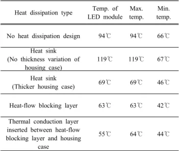
구리를 방열판으로 사용하는 이유는 열전도도가 알류미늄에 비하여 약 2배가량 높기 때문이다. 알루 미늄의 열전도도를 보면 알류미늄의 경우 237 W/m.k 구리는 400 W/m.k 임을 확인 할 수 있다. 이러한 이 유로 구리를 이용하여 방열판을 구성하였다. 그림 11 과 12는 LED 모듈과 검측 모듈 하우징 외벽에 추가적 인 방열 설계를 한 후 내부 온도 분포를 나타낸 것이 다. 또한 표 1은 다양한 방열 조건에서의 LED 모듈 온도 및 검측 모듈 내부의 최대, 최소 온도를 나타내었다.
Table 1. Temperature variation of the rail anchoring failure detection module under different heat dissipation conditions.
Heat dissipation type Temp. of LED module
Max.
temp.
Min.
temp.
No heat dissipation design 94℃ 94℃ 66℃
Heat sink (No thickness variation of
housing case)
119℃ 119℃ 67℃
Heat sink
(Thicker housing case) 69℃ 69℃ 46℃
Heat-flow blocking layer 63℃ 63℃ 42℃
Thermal conduction layer inserted between heat-flow blocking layer and housing
case
55℃ 64℃ 44℃
그림 및 표에서 검측 모듈 내부의 최대 및 최소 온도 는 추가 방열 설계 전과 큰 차이가 없는 것으로 조사 되었으나, 전체적으로 검측 모듈 내부의 온도가 내려가 45℃ 이하 온도 부분이 많아졌음을 알 수 있었다. 특 히, 그림 12에서 볼 수 있듯이 LED 모듈의 온도가 5 5℃ 이하로 낮아지는데, LED 모듈과 외부 하우징 사 이에 구리 재질의 방열판으로 인하여 LED 모듈에서 발생한 열이 구리 재질의 방열판을 통해 외부로 전달 이 되어 온도가 내려가고 있음을 확인할 수 있었다.
4. 결 론
열차 하부와 같이 제한된 공간과 외부에서 공기의 유입이 없다는 환경조건에서의 방열 설계를 할 경우, 방열 팬 적용의 어려움과 같은 많은 제약 조건이 존재 한다. 특히, 레일 체결구 결함 검측 모듈과 같이 촬영 을 위해 고출력의 LED 모듈을 사용하는 경우, 발열량 이 상당하기 때문에 기존 방열 설계와는 다른 접근 방 법이 필요하다.
본 논문에서는 제한된 공간 및 환경에서도 적용 가 능한 다양한 방열 설계의 열 해석을 통해 검측 모듈 내부의 온도를 낮출 수 있는 방법들을 제시하였다. 특히, LED 모듈에서 발생한 열이 내부로 전달되는 것을 차 단하여 외부로 열을 전달해주는 차단막 또는 내부 남 아있는 공간을 활용한 히트싱크 구성 등을 통해 효과
분의 내부 온도는 55℃ 이하로 감소하였다. 또한 LED 모듈과 외부 하우징 사이의 공간에 구리 재질의 heat sink를 적용할 경우, LED 모듈 측의 온도도 55℃ 이하 로 낮아짐을 알 수 있었다. 그러나 본 논문에서 사용한 열 해석 프로그램의 경우, 다양한 재료의 재질을 선택할 수가 없었으나 보다 우수한 열 전도성 물질을 적용하여 열 해석을 실시할 경우, 더 뛰어난 방열 성능이 나오리 라고 기대한다. 또한 열 해석 프로그램의 경우, 실제 검 측 모듈에서 측정한 온도와 차이가 있을 수 있으나, 방 열 설계 효과를 예측할 수 있어 제작 시간 및 비용의 절 감하는데 있어서는 우수하다고 판단이 된다.
감사의 글
본 논문은 국토교통부 및 국토교통과학기술진흥원이 시행하는 철도기술개발사업 “고속 궤도 검측 모듈 개 발”에서 수행된 내용입니다.
[3] K. W. Ko, D. H. Kim, D. S. Kang, S. Y. Kwon, Annual of fall conference The Institue of Electronics Engineers of Korea, 680 (2013).
[4] I. Y. Choi, J. S. Lee, J. H. Um, T. K. Kang, M. J. Choi, Journal of the Korean Society for Railway, 18, 63 (2015).
[DOI: http://dx.doi.org/10.7782/JKSR.2015.18.1.63]
[5] J. S. Ban, Y. H. Jung, H. S. Yang, S. J. Kim, Journal of the Korean Society for Precision Engineering, 29, 109 (2012). [DOI: http://dx.doi.org/10.7736/KSPE.2012.29.1.109]
[6] S. I. Lee, C. Y. Chang, M. S. Song, Annual of fall conference Korean Society for Railway, 959 (2014).
[7] C. W. Yu, K. H. Min, D. H. Seo, H. H. Son, H. J.
Choi, S. J. Jo, C. W. Choi, and H. S. Ko, Annual of fall conference The Korean Society of Mechanical Engineers, 1629, (2012).
[8] C. S. Kang, K. S. Kang, The Institute of Electronics Engineers of Korea, 48(2), 12 (2011).
[9] J. S. Choi, Journal of the KSME, 50(4), 22 (2010).
[10] S. O. Kasap, Principle of Electronic Materials and Devices (McGraw-Hill, Singapore, 2006) p. 149.