고압 천연 가스 인젝터의 분무 특성에 관한 연구
삭다 통차이1⋅강유진1⋅임옥택2,†
1울산대학교 기계공학부 대학원, 2울산대학교 기계공학부
An Investigation on the Spray Characteristics of a Compressed Natural Gas Injector
SAKDA THONGCHAI
1, YUJIN KANG
1, OCKTAECK LIM
2,†1Graduate School of Department of Mechanical Engineering, University of Ulsan, 93 Daehak-ro, Nam-gu, Ulsan 44610, Korea
2School of Mechanical Engineering, University of Ulsan, 93 Daehak-ro, Nam-gu, Ulsan 44610, Korea
†
Corresponding author :
[email protected]Received
6 April, 2018Revised
25 April, 2018Accepted
30 April, 2018Abstract >> This study was carried out to investigate the injection characteristics of 800 kPa compressed natural gas compressed natural gas (CNG) injector de- veloped in Korea. The CNG injector with multi-holes, employed in this experi- ment, was designed to inject CNG in the manifold at high pressure of 800 kPa.
The spray macroscopic visualization test was carried out via Schlieren photog- raphy to study fuel-air mixing process. The fundamental spray characteristics, such as spray penetration, spray cone angle and spray velocity, were evaluated in the constant volume combustion chamber (CVCC) with varying the constant back pressure in CVCC from 0 to 1.8 bar. For the safety reason, nitrogen (N
2) and an acetone tracer were utilized as a surrogate gas fuel instead of CNG. The surro- gate gas fuel pressures were controlled at 3, 5.5, and 8 bar, respectively.
Injection durations were set at 5 ms throughout the experiment. The simulating events of the low engine speed were arranged at 1,000 rpm. The spray images were recorded by using a high-speed camera with a frame rate of 10,000
at 512×256 pixels. The spray characteristics were analyzed by using the image processing (Matlab). The results showed the significant difference that higher in- jection pressure had more effect on the spray shape than the lower injection pressure. When the injection pressure was increased, the longer spray pene- tration occurred. Moreover, the linear relation between speed and time are de- pendent on the injection pressure as well.
Key words : Spray penetration(분무관통길이), Spray cone angle(분무각), Schlieren (슐리렌계측), Tracer(형광표시자), Constant volume combustion cham- ber(정적연소기)
219
Table 1. General data of CNG injector
Description Value
Model 800
(Prototype)Type Solenoid injector
Number of hole 4 holes
Tip diameter 6 mm.
Max. operating pressure 8 bar.
Input voltage 10-14 V.
있다 . 또한 전 세계적으로 많은 국가들이 환경을 쾌적하게 유지하고자 하는 움직임을 보이고 있고, 지구의 환경을 쾌적하게 유지 하게 위해 수많은 연 구와 그에 따른 많은 규제들이 제정 되고 있다 . 따라 서 에너지 위기와 대기 오염 및 배기가스 배출 규제 와 관련하여 천연가스는 가장 중요한 대체 연료 중 하나이며 가장 깨끗한 화석 연료로 간주된다 . 풍부 한 천연가스는 내연기관의 연료로서 넓게 사용되는 매력적인 요소이다
2). 따라서 많은 엔진 연구자들 및 엔진 개발 기업들도 천연 가스 엔진에 대한 연구에 관심을 가지고 있으며, 한국 자동차 부품 연구원에 서는 CNG 레귤레이터의 특성에 관한 연구를 진행 하였으며, 한국 기계 연구원에서는 한 걸음 나아가 수소-CNG 혼합연료 시스템에 대한 적용성 평가를 진행하는 등 현재 많은 엔진 연구자 및 엔진 개발 기업들이 천연가스를 이용하는 엔진 시스템을 개발 및 효율을 높이기 위한 연구를 진행 중에 있다 . 본 논문에서는 국내에서 개발된 고압 CNG 인젝터의 분사 압력을 변화시켜 정적연소기(constant volume combustion chamber, CVCC) 내에서의 분사 특성을 연구하였다. 분무 거동을 이해하기 위하여, 거시적 분 무 시각화는 슐리렌 계측법을 통해 조사되었으며
3,4), 분무관통길이 및 분무각 , 분무 속도를 분석하여 연 료-공기 혼합 공정을 연구하였다.
2. 실험 장치 및 실험 방법
2.1 실험 장치 구성
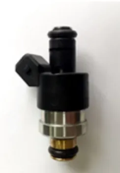
분무 특성 관찰을 위해 사용된 고압 CNG 인젝터
는 솔레노이드 인젝터이며, Fig. 1에 나타나 있다.
Fig. 1의 인젝터 사양은 Table 1에 나타나 있고, 노 즐 홀은 4개, 노즐 출구의 직경은 6 mm이고, 최대분 사압력은 8 bar이다. 질량유량계를 사용하여 분무특 성과 분사질량유량을 측정하여 분석하였고, 정적연 소기(CVCC)에 장착하였다. 안전상의 이유로 CNG 를 사용하지 않고 아세톤 형광 표시자를 혼합한 질 소(N
2)를 대체 가스로 사용하였고, 이것이 이 연구 의 한계점으로 작용한다
5-8). N
2-아세톤 혼합물이기 때문에 CNG의 특성과 약간 다를 수 있다.
분사압력은 3, 5.5 및 8 bar로 설정 하였고, 정적연 소기의 분위기압은 1.0, 1.4 및 1.8 bar로 설정하였고 모든 압력은 게이지 압력으로 표기되었다 . 분사기간은 실험 전반에 걸쳐 5 ms 동안 전기를 공급함으로써 제 어되었다 . 분무관통길이, 분무각 및 분무 속도는 고속 카메라를 이용하여 이미지 촬영 후 분석하였다
9,10).
2.2 분무 가시화분무가시화 실험은 Fig. 2와 같이 Z-형식으로 배
Fig. 2. The spray visualization setup with the Schlieren pho-
tography technic (Z-type)Fig. 3. The picture of spray visualization system
Fig. 4. The definition of spray cone angle and penetration
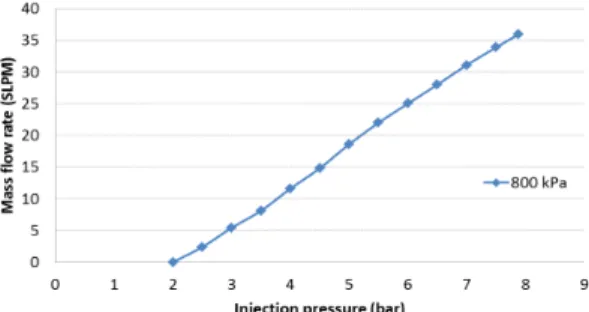
lengthFig. 5. The injection mass flow rate with N2 at the variation in-
jection pressure.열된 슐리렌계측을 사용하여 진행되었고, 그 시스템 은 Fig. 3에 나타나 있다. 슐리렌계측은 매질 중, 밀 도 차에 의해 굴절률이 변화하는 부분이 있을 때, 빛 의 진행방향의 변화를 이용하여 육안 또는 사진 촬 영으로 그 모양을 관찰하는 방법이다 . 이를 통해 정 적연소기 내에 대체연료의 분무 거동을 관찰하기 위하 여 사용하였다. 분무이미지는 프레임 속도 10,000
의 고속 카메라 Photron-model S3을 사용하여 촬영 하였다. 모든 분무 이미지는 Protron FASTCAM Viewer (PFV) 소프트웨어를 통해 컴퓨터에 저장되 었고, 분무 특성은 이미지 프로세싱(Matlab)을 사용 하여 분석하였다 .
3. 결과 및 고찰
분무 특성 실험은 분위기압 1.0, 1.4 및 1.8 bar,
분사압력 3, 5.5 및 8 bar, 분무 기간 5 ms의 분무 조건으로 진행 되었다 . 분무각 및 분무관통길이의 정의는 다음과 같으며 Fig. 4에 표시되어있다
11). 분 무각(
)은 노즐 끝단에서부터 분무관통길이의 끝단 까지 측정되었고 , 분무관통길이(
)는 노즐 팁의 끝 에서 마지막 픽셀이 있는 분무 팁의 끝까지의 거리 를 측정하였다.
Matlab 프로그램을 이용한 이미지 프로세싱을 통 해 측정된 CNG 인젝터의 질량유량은 Fig. 5를 통하여 볼 수 있다 . 인젝터의 질량유량은 분사압력이 0.5씩 증 가함에 따라 약 3 standard liter per minute (SLPM)씩 의 증가량을 보였으며 , 8 bar에 가까워질수록 증가 량이 줄어들었지만 무시할 만한 수준이었다. 분사압력 이 높을수록 분무속도가 높아져 질량 유량이 증가하였 고, 최대 질량 유속은 8 bar에서 36 SLPM이었다.
분사압력과 분무각의 상관관계는 Fig. 6에 나타나
있다. Fig. 6을 보면 분무압력이 낮을 때의 결과는
(b)
(c)
Fig. 6. The spray cone angle of injection pressure (a) 3 bar,
(b) 5.5 bar and (c) 8 bar with varying back pressure분무각이 24-27° 정도 감소하였고 분위기압 1.0 bar 보다 1.4 bar, 1.8 bar일 때 각각 4.78%, 6.09% 적게 나타났다. 분사압력이 높을수록 분무각이 좁은 형상 을 보였는데 이는 분사압력이 높을수록 분무 관통거 리가 길어지고 , 이에 따라 분무입자들이 분무의 끝 단에 이르기까지 주위로 흩어지지 않고 분사되었기 때문이라고 판단된다.
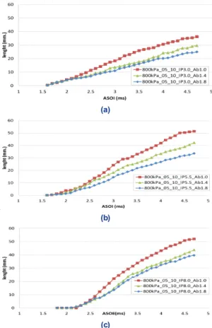
분무 관통 거리는 실제 엔진의 연소실 크기 및 연 소시 나타나는 현상을 예측하기 위하여 사용되는 중 요한 분무 특성중 하나이다. Fig. 7는 정적연소기내 에서 분무압력 8 bar에서 분위기압의 변화에 따른
무 관통 거리를 조사하기 위하여 일정 분사압력에서 분위기압을 각각 1.0 bar, 1.4 bar, 1.8 bar의 조건으로 측정한 결과를 나타낸다. Fig. 8의 (c)는 8.0 bar의 분 사압력에서 분위기압이 1.0일 때, 1.4 bar에서보다 분 무 관통 거리가 21.3% 길게 나타났고, 1.8 bar에서보 다는 26.8% 길게 나타났다. 이러한 결과를 보이는 이유는 아래와 같다. 분사압력이 증가하여 분무속도 또한 증가하며 , 이로 인해 분무 운동량이 증가되어 분무 관통 거리가 증가되는 것이다 . 분위기압력이 증 가함에 따라 연소실내 공기의 밀도가 높아지면 압력 차가 감소하여 분무속도가 감소하고 분무진행 방향 의 항력이 커져서 분무 관통 거리가 감소되는 것으 로 판단된다 . 위의 결과는 Lee 등
12)의 연구 결과를 통해서도 확인이 가능하며, 분무관통길이는 아래의 식과 같이 표현된다.
≺ ≺
≺
여기서 S는 분무 거리, 는 분사압력과 주변압 력의 차이 , t는 시간,
는 노즐 직경,
는 분열 시 간,
는 연료밀도,
는 주변가스밀도를 나타낸다.
따라서 분위기압이 증가하면 연료압력과 분위기압
력간의 압력차이가 감소하며 , 이와는 반비례하게 분
무관통거리가 증가한다는 것을 위의 식을 통해 알
수 있다
13). 따라서 분위기압이 분무관통거리에 영향
을 미치는 중요 인자라는 것을 확인 하였다 .
(a)
(b)
(c)
Fig. 7. The spray developed patterns of (a) injection pressure 8 bar and back pressure1.0 bar, (b) Injection pressure 8 bar, back
pressure 1.4 bar and Injection pressure 8 bar, back pressure 1.8 bar(a)
(b)
(c)
Fig. 8. Effect of the injection pressure on the spray pene-
trations at (a) 3, (b) 5.5, and (c) 8 bar with the variations of the back pressure(a)
(b)
(c)
Fig. 9. Effect of the injection pressure on the spray speed at (a) 3,
(b) 5.5, and (c) 8 bar with the variations of the back pressure않는다 . 따라서 위의 두 상황에서는 분사속도가 매 우 흡사하게 나타났다. Fig. 9의 그래프 (C)에서 분 사압력 8 bar, 분위기압 1.0 bar일 때의 분사속도는 1.4 bar, 1.8 bar의 측정 결과와 비교하여 각각 21.9% , 26.9% 크게 나타났다. 하지만 분사압력이 높을 때 연료의 분사가 늦게 나타났는데, 이는 분사 초기의 분사압력과 분위기압의 압력차이 때문이라 고 판단된다.
4. 결 론
본 논문에서는 개발된 CNG 인젝터의 질량 유속, 분사압력에 따른 가스 분사속도 등 분무특성을 고찰 하기 위하여 정적연소기 내에 CNG 연료의 안전성 문제로 N
2형광표시자를 대체연료로 분사하여 관찰 하고 조사하였다. 분무 거동을 분석하기 위해 슐리 렌 사진 기법 및 이미지 프로세싱이 실험 전반에 걸 쳐 적용되었고, Fig. 6, Fig. 8, Fig. 9에 모든 결과들 은 분사압력이 각각 3, 5.5, 8 bar에서 분위기압이 1.0 bar, 1.4 bar, 1.8 bar로 달라질 때 측정된 값들과 비교하였다. 본 실험에서 도출된 결과에서 중요한 내용들을 아래와 같이 요약하였다.
1) 인젝터의 최대분사압력 내에서, 분사압력이 높 을수록 분사속도가 높아지고 그에 따라 분사질량유 량이 분사압력의 증가와 비례하여 증가한다. 실험에 서는 분사압력이 0.5 증가함에 따라 분사유량은 약 3 SLPM 증가하는 모습을 보였다.
2) 분사압력이 높을수록 분무 형상에 더 많은 영 향을 미쳤다. 분사압력이 높고, 분위기압이 낮을 때 분무관통거리는 본 논문의 실험조건에서 1.4 bar, 1.8
사압력에 따라 달라진다. 분사압력이 높을수록 분사 속도가 높아짐을 보였다. 분사압력이 낮으면 인젝터 홀 부근에서 분위기압의 영향으로 분사가 일어나기 어렵다. 따라서 분사압력이 높을 때 분사가 더 쉽고 빠르게 일어났다.
후 기
본 연구는 산업통상자원부의 산업핵심기술개발사 업(G01201706010530, 800kPa급 고압·고정밀 NGV 연료시스템 국산화 개발 )의 지원을 받아 이루어졌다.
References
1. S. Moon, N. Jo, C. Nam, H. Lee, J. Kim, and W. Jeon, “A Numerical Study on Injection Pattern Characteristics of Fuel Systems”, Korean Society of Automotive Engineering, KSAE17-B0145, 2017, p. 276.
2. C. Bae and J. Kim, “Alternative fuels for internal combus- tion engines”, Proceeding of the Combust Institute, Vol. 36, No. 3, 2017, pp. 3389-3413.
3. G. S. Settles, “Schlieren and shadowgraph Techniques”, 1st edition, Springer, USA, 2001, pp. 23-46.
4. A. Mazumdar, “Principles and Techniques of Schlieren Imaging”, Columbia University, 2011, pp. 1-16.
5. L. Yu, H. Hillamo, T. Sarjovaara, T. Hulkkonen, and O.
Kaario, “Experimental Study on Structure and Mixing of Low-Pressure Gas Jet Using Tracer-Based PLIF Technique”, SAE international Tech Pap, 2011, 2011-24-0039.
6. J. Yu, V. Vuorinen, H. Hillamo, T. Sarjovaara, O. Kaario, and M. Larmi, “An Experimental Study on High Pressure Pulsed Jets for DI Gas Engine Using Planar Laser-Induced Fluorescence”, SAE international Tech Pap, 2012, 2012-01- 1655.
7. J. Yu, V. Vuorinen, O. Kaario, T. Sarjovaara, and M. Larmi,
“Visualization and analysis of the characteristics of transi- tional underexpanded jets”, International Journal of Heat and Fluid Flow, Vol. 44, 2013, pp. 140-154.
8. J. Yu, V. Vuorinen, H. Hillamo, T. Sarjovaara, O. Kaario, M.
Larmi, “An experimental investigation on the flow struc- ture and mixture formation of low pressure ratio wall-im- pinging jets by a natural gas injector”, Journal of National Gas Science and Engineering, Vol. 9, 2012, pp. 1-10.
9. A. Barriga-Rivera and G. J. Suaning, "Digital image process- ing for visual prosthesis: Filtering implications," 2011 Annual International Conference of the IEEE Engineering in Medicine and Biology Society, Boston, 2011, pp. 4860-4863.
10. Mathworks. Image Processing ToolboxTM User’sGuideR2014b, 2014, p. 664.
11. Y. Liu, J. Yeom, and S. Chung, “A study of spray develop- ment and combustion propagation processes of spark-ig- nited direct injection (SIDI) compressed natural gas (CNG)”, Mathmatical and Computer Modeling, Vol. 57, No. 1-2, 2013, pp. 228-244.
12. S. Lee, Y. Kim, and S. Park, “Spray Characteristics of the GDI Injector”, Korean Society of Automotive Engineering, KSAE11-B0045, 2011, pp. 252-255.
13. S. Lee and O. Lim, “An Investigation on the Spray Characteristics of DME with Variation of Nozzle Holes Diameter using the Common Rail Fuel Injection System”, Korean Society of Automotive Engineering, Vol. 21, No. 4, 2013, pp. 1-7.