Control of a Rotary Inverted Pendulum System Using Brain Emotional Learning Based Intelligent Controller
Jae-Won Kima, Chae-Youn Ohb*
BELBIC을 이용한 Rotary Inverted Pendulum 제어 김재원a, 오재윤b*
a Department of Bio-Nano System Engineering, Chonbuk National University, 664-14 1-Ga, Deokjin-Dong, Deokjin-Gu, Jeonju, Jeonbuk, 561-756, Republic of Korea
b Division of Mechanical System Engineering, Chonbuk National University, 664-14 1-Ga, Deokjin-Dong, Deokjin-Gu, Jeonju, Jeonbuk, 561-756, Republic of Korea
ARTICLE INFO ABSTRACT
Article history: This study performs erection of a pendulum hanging at a free end of an arm by rotating the arm to the upright position. A mathematical model of a rotary inverted pendulum system (RIPS) is derived. A brain emotional learning based intelligent controller (BELBIC) is designed and used as a controller for swinging up and balancing the pendulum of the RIPS. In simulations performed in the study, a pendulum is initially inclined at 45°
with respect to the upright position. A simulation is also performed for evaluating the adaptiveness of the designed BELBIC in the case of system variation. In addition, a simulation is performed for evaluating the robustness of the designed BELBIC against a disturbance in the control input.
Received 15 April 2013
Revised 12 July 2013
Accepted 23 September 2013 Keywords:
BELBIC (Brain Emotional Learning Based Intelligent Controller)
RIPS (Rotary Inverted Pendulum System) SI (Sensory Input)
ES (Emotional Signal) End mass
Adaptiveness Robustness
* Corresponding author. Tel.: +82-63-270-2377 Fax: +82-63-270-2388 E-mail address: [email protected] (Chae-Youn Oh).
1. Introduction
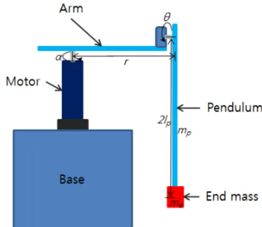
A rotary inverted pendulum System (RIPS) is composed of three parts; motor, arm, and pendulum. The pendulum is hanging at free end of arm. The pendulum sways in a vertical plane by kinetic energy which is generated by rotational movement of the arm. The arm is connected to the shaft of the motor, rotates in a horizontal plane with the shaft of the motor, and
swings the pendulum to erect it upward position. Control problem of a RIPS is composed of two processes. One process is to swing a pendulum for erecting upward position. The other process is to balance the pendulum at upright position. In a RIPS, since upright position of the pendulum is naturally unstable, control for raising the pendulum to upward position, and then balancing the pendulum by rotating the arm from downward position of the pendulum which is naturally stable
Fig. 1 Schematic diagram of an inverted pendulum system is difficult. In addition, what makes control of a RIPS difficult
basically is that a RIPS is a nonminimum system as well as an underactuated system which has more joint than actuator.
A RIPS has been utilized as a test-bed for evaluating an efficiency and effectiveness of a new control scheme.
Control schemes based on linearization[1,2] have been proposed for RIPS control. Linear controllers are simple to design.
However, they can be applied for RIPS control only in the vicinity of an operating point. In order to overcome the shortcoming inherent in linear controllers, a variety of nonlinear control schemes such as gradient-based nonlinear model predictive control[3], genetic algorithm[4,5], and fuzzy control[6]
have been studied for RIPS control.
However, those nonlinear control schemes have difficulties finding control rules which exhibit the highest levels of performance. Hybrid control schemes[7-10] which combine merits of a linear control (PD (Proportional-Derivative), PID (Proportional-Integral-Derivative) or LQR (Linear Quadratic Regulation) controller) and nonlinear control scheme (Fuzzy or neural Network controller) have been proposed. However, those hybrid controllers show difficulties to cope with parameter variations and external disturbances.
One of intelligent controllers which attracts attention recently is Brain Emotional Learning Based Intelligent Controller (BELBIC). BELBIC is a controller which describes inter- relationship of Limbic system's major organs such as Amygdala, Orbitofrontal cortex (OFC), Thalamus, and Sensory cortex mathematically to mimic emotional learning process of a mammal[11,12]. BELBIC is easy to implement, is able to apply for a real time control because of less computational load, and shows a good robustness and adaptiveness. BELBIC was applied to variety systems not only which can be described as a linear model[11,13] but also which have a large nonlinearity and various conditions[14,15]. Until now, a study using BELBIC for control a RIPS has not been reported in the literature.
This paper derives a mathematical model of a RIPS, and designs BELBIC as a controller for control the arm and pendulum of a RIPS. A simulation for evaluating adaptiveness of developed BELBIC for a system variation is performed. In addition, a simulation for evaluating robustness of developed BELBIC for disturbance of control input is performed.
2. Modeling of a rotary inverted pendulum system
A RIPS considered in this paper connects an arm with a motor shaft, and connects a pendulum at free end of the arm as shown in Fig. 1. Forces N and P given in Equations (1) and (2) respectively are forces acting at a joint connecting the pendulum and rotating arm. They are given by following two equations.
′′sin ′cos (1)
′ ′ ′cos ′sin (2)
In Eqs. (1) and (2), α represents a rotational position of the arm, and θ represents a rotational position of the pendulum.
r is a length of the arm, lp is a length from a joint to the mass center of the pendulum, and 2lp is a length of the pendulum.
mp is a mass of the pendulum, and me is a mass of an additional mass (called end mass) attached at the end of the pendulum.
In addition, ′ , and ′
. If we apply Newton's law to the RIPS, we derive the equations of motion of the RIPS as follows.
(3)
′cos ′sin (4)
In Eqs. (3) and (4), Jp is a mass moment of the pendulum,
Table 1 Dimensions and descriptions of parameters for RIPS Parameter Value Unit Description
mp 0.1 kg Mass of the pendulum me - kg Mass of the end mass
r 0.19 m Length of the arm
lp 0.203 m Length from a joint to the mass center of the pendulum Ja 0.0108 Nm2 Mass moment of the arm Jp 0.005 Nm2 Mass moment of the
pendulum
Kt 0.0302 Nm/A Torque constant of the motor Kb 0.0301 Vsec/rad Back electromotive force
constant of the motor Ra 0.316 Ω Electric resistance of the
motor
n 15 - Gear ratio of the motor cp 0.0777 Nmsec/rad Damping coefficients of the
pendulum joint
ca 0.61 Nmsec/rad Damping coefficients of the motor
g 9.8 m/sec2 Acceleration of gravity and Ja is a mass moment of the arm. T is a torque generated by the deriving motor. cp and ca are damping coefficients of the joint and the motor respectively. If Eqs. (3) and (4) are rearranged with respect to and , the equations of motion of the RIPS are represented by the following Equations.
′′′ ′′cos
′′ ′′sin ′′
′′′ ′′cos
′′cos′′ sin
′′′ ′′cos
′′cos ′′sincos
′′′ ′′cos
′′sin ′
A torque generated by the driving motor is represented by the following equation.
(7) In Eq. (7), n is a gear ratio of the motor, V is an input voltage,
Ra is an electric resistance of the motor, Kt is a torque constant, and Kb is a back electromotive force constant. Table 1 shows dimensions and descriptions of parameters for RIPS considered in this paper.
3. BELBIC
This paper performs a study on erecting a pendulum hanging at a free end of an arm by rotating an arm to upright position using BELBIC. Control inputs of BELBIC are sensory input (SI), and internal reward signal. SI is induced by external sensory organ's output against stimuli. Reward signal is a emotional learning value, and also called as emotional signal (ES). BELBIC was described in discrete form as follows[11].
× (8)
× (9)
∆ × × max (10)
∆ × × (11)
(12)
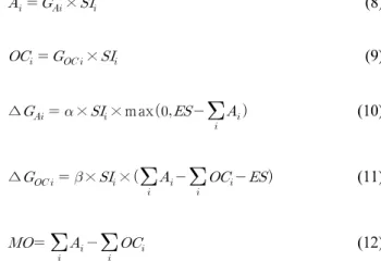
Eqs. (8) and (9) are output of amygdala (Ai) and OFC (OCi) respectively. In Eq. (9), GOCi is a gain of OFC, and SI is sensory input. Output of OFC represented by Eq. (9) performs a role to regulate output of amygdala. In Eq. (10), we can see that GAi, gain of amygdala, always increases monotonically. It is very close to the fact that emotional value of mammalian limbic system's amygdala increases against input stimuli, and then is delivered. In the equation, ES represents emotional signal. Eqs.
(10) and (11) are used for update GAi and GOCi respectively.
In Eqs. (10) and (11), α and β represent learning rates. They are generally assigned to the same value. Otherwise, a bigger value is assigned to α. The control effort of BELBIC, MO is represented by Eq. (12), and is a difference of amygdala output and OFC output. BELBIC described in discrete form has a shortcoming that it acts discontinuously against stimuli.
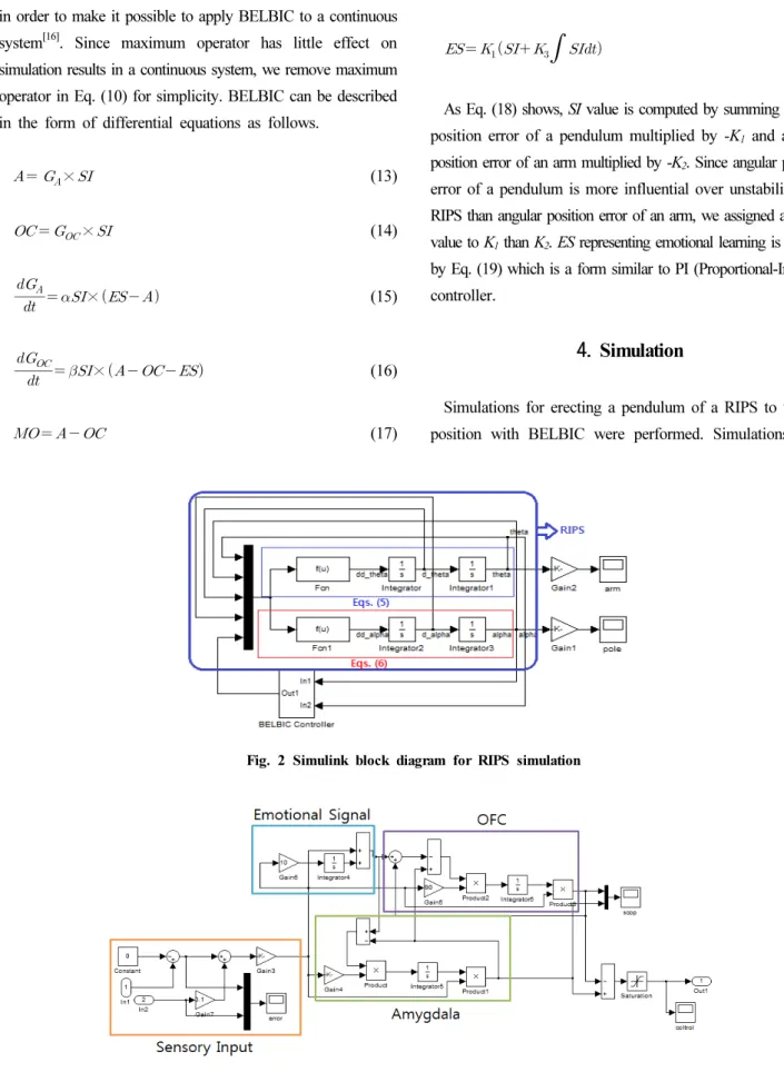
Fig. 2 Simulink block diagram for RIPS simulation
Fig. 3 BELBIC controller block diagram for RIPS simulation BELBIC was described in the form of differential equations
in order to make it possible to apply BELBIC to a continuous system[16]. Since maximum operator has little effect on simulation results in a continuous system, we remove maximum operator in Eq. (10) for simplicity. BELBIC can be described in the form of differential equations as follows.
× (13)
× (14)
× (15)
× (16)
(17)
(18)
(19)
As Eq. (18) shows, SI value is computed by summing angular position error of a pendulum multiplied by -K1 and angular position error of an arm multiplied by -K2. Since angular position error of a pendulum is more influential over unstability of a RIPS than angular position error of an arm, we assigned a bigger value to K1 than K2. ES representing emotional learning is defined by Eq. (19) which is a form similar to PI (Proportional-Integral) controller.
4. Simulation
Simulations for erecting a pendulum of a RIPS to upright position with BELBIC were performed. Simulations were
(a) Angular displacement of pendulum (b) Angular displacement of arm
(c) BELBIC output (d) Amygdala and OFC output
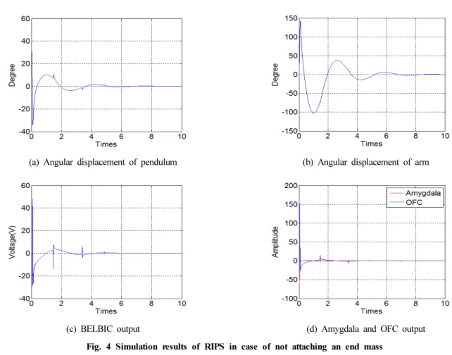
Fig. 4 Simulation results of RIPS in case of not attaching an end mass
(a) Angular displacement of pendulum (b) Angular displacement of arm
(c) BELBIC output (d) Amygdala and OFC output
Fig. 5 Simulation results of RIPS in case of attaching an end mass
Fig. 6 Noise added to BELBIC output
(a) Angular displacement of pendulum (b) Angular displacement of arm
(c) BELBIC output (d) Amygdala and OFC output
Fig. 7 Simulation results of RIPS in case of adding a noise performed with MATLAB Simulink[17]. Fig. 2 and 3 shows
a block diagram composed with MATLAB Simulink, and used for simulations.
In simulations performed in this paper, a pendulum was inclined 45° with respect to upright position initially. Five coefficients required for design BELBIC were found by trial and error method, and set to K1=200, K2=20, K3=10, α=100 and β=90. First, we performed a simulation with a pendulum at which an end mass was not attached at the end the pendulum.
Then, we performed a simulation with a pendulum attached an end mass in order to evaluate adaptiveness against a system
variation of defined BELBIC. Finally, we performed a simulation with a motor control input disturbed by a noise in order to evaluate robustness against external disturbance of defined BELBIC.
Figs. 4 show results of the simulation performed with a pendulum not attached an end mass. As Fig. 4(a) shows, a big control input was applied to the motor at the very beginning of simulation. The big control input rotated the arm toward the inclined pendulum drastically to erect the pendulum upright position. Then, after the arm wagged twice, the pendulum balanced at upright position. The pendulum was reached at a steady state in around 5 seconds.
In order to show adaptiveness of BELBIC, a simulation was performed with a pendulum attached an end mass, and with BELBIC used in the above simulation. The end mass has a weight of half of the pendulum. Figs. 5 show simulation results.
As Figs. 5 show, the pendulum and arm reached in a steady state after they wagged one and half. The pendulum reached in a steady state faster in the simulation performed with an end mass than in the simulation performed without an end mass.
The faster stabilization was resulted because the end mass played a role as a stabilizing weight.
In order to show robustness of BELBIC, a simulation was performed with motor control input in which a noise was added as external disturbance, and with BELBIC used in the above simulations. A pendulum with an end mass was used in the simulation. A noise added to motor control input was generated by combining a sinusoidal wave having a period of 0.5Hz and an amplitude of ±2V, and a white noise having a sampling rate of 100Hz and an amplitude of ±2V. Fig. 6 shows a noise used in this paper.
Figs. 7 show simulation results. As Figs. 7(a) and (b) show, BELBIC controlled the arm and pendulum stably regardless of added noise. In spite of adding a noise to control input, angular displacements of the arm and pendulum shown in Figs.
7(a) and (b) (with a noise) were about the same as those shown in Figs. 5(a) and (b) (without a noise).
As Figs. 5(c) and 7(c) show, chattering was occurred in BELBIC output. It was occurred since Amygdala and OFC outputs correct interactively in a high frequency mode to balance the pendulum at upright position by coping with drastically increased instability due to an end mass, and external disturbance. In Figs. 4(a), 5(a), and 7(a), a jerk was occurred around 1.3 sec. The jerk was occurred when Amygdala and OFC outputs have the same value while they are moving opposite direction before they reach a steady state.
5. Conclusions
This paper derived a mathematical model of a RIPS. BELBIC was designed, and used for swing up the pendulum and balancing the pendulum at upright position. Five parameters required to design BELBIC were set to K1=200, K2=20, K3=10, α=100
and β=90. In simulations performed in this paper, a pendulum was inclined 45° with respect to upright position initially. In the simulation performed with a pendulum not attached an end mass, the pendulum reached at a steady state in around 5 seconds.
A simulation was performed with a pendulum attached an end mass, and with BELBIC used in the above simulation. The pendulum reached in a steady state faster in the simulation performed with an end mass than in the simulation performed without an end mass. However, control input showed a continuous chattering for balancing the pendulum at upright position after the pendulum reached in a steady state. In addition, a simulation was performed with motor control input in which a noise was added as external disturbance, and with BELBIC used in the above simulations. BELBIC controlled the arm and pendulum stably regardless of added noise. In spite of adding a noise to control input, angular displacements of the arm and pendulum in case of adding a noise were about the same as those in case of not adding a noise. Therefore, we can say that BELBIC designed in this paper showed adaptiveness against a system variation, and robustness against external disturbance of control input.
References
[1] Iraj, H., Saleh, M., Abbas, H., 2008, Input-Output Feedback Linearization Cascade Controller Using Genetic Algorithm for Rotary Inverted Pendulum System, American Journal of Applied Sciences 5:10 1322~1328.
[2] Lachhab, N., Abbas, H., Werner, H., 2008, A neural- network based technique for modelling and LPV control of an arm-driven inverted pendulum, Decision and Control 47th IEEE Conference 3860~3865.
[3] Jung, S., Wen, J. T., 2004, Nonlinear Model Predictive Control for the Swing-Up of a Rotary Inverted Pendulum, Journal of Dynamic Systems Measurement and Control 126 666~673.
[4] Kaise, N., Fujimoto, Y., 1999, Applying the evolutionary neural networks with genetic algorithms to control a rolling inverted pendulum, Springer Berlin Heidelberg 223~230.
[5] Jung, D. Y., Kim, H. R., Han, S. H., 2004, Intelligent Controller of Mobile Robot Using Genetic Algorithm, KSMTE Spring Conference 2004 181~186.
[6] Tack, H. H., Kim, M. G., 2001, The Stabilization control of inverted pendulum system using neuro fuzzy control algorithm, Agricultural Technology Institute of Jinju Industrial College 14 207~214.
[7] Melba, M. P., Marimuthu, N. S., 2008, Design of intelligent hybrid controller for swing-up and stabilization of rotary inverted pendulum, ARPN Journal of Engineering and Applied Sciences 3:4 60~70.
[8] Roh, S. B., Oh, S. K., 2001, The Design of hybrid fuzzy controller for inverted pendulum, KIEE Summer Conference 2702~2704.
[9] Krishen, J., Becerra, V. M., 2006, Efficient fuzzy control of a rotary inverted pendulum based on LQR mapping, IEEE International Symposium on Intelligent Control 2701~2706.
[10] Fallahi, M., Azadi, S., 2009, Adaptive Control of an Inverted Pendulum Using Adaptive PID Neural Network, IEEE International Conference on Signal Processing System 589~593.
[11] Lucas, C., Shahmirzadi, D., Sheikholeslami, N., 2004, Introducing BELBIC : Brain Emotional Learning Based Intelligent Control, Intelligent Automation and Soft
Computing 10:1 11~22.
[12] Moren, J., 2002, Emotion and Learning, Doctorate Thesis, Department of Cognitive Science Lund University, Sweden.
[13] Rashidi, F., Rashidi, M., Hashemi, A., 2003, Appling intelligent controllers for speed regulation of DC motor, The 11th Mediterranean Conference on Control and Automation 1~6.
[14] Jafarzadeh, S., Mirheidari, R., Jahed-Motlagh, M. R., Barkhordari, M., 2008, Designing PID and BELBIC controllers in path tracking problem, International Journal of Computers Communications & Control 3 343~348.
[15] Valizadeh, S., Jamali, M. R., Lucas, C., 2008, A particle- swarm-based approach for optimum design of BELBIC controller in AVR system, ICCAS 2008 International Conference on. IEEE 2679~2684.
[16] Arpit, J., 2009, Computational modeling of the brain limbic system and its application in control engineering, Master Thesis, Engineering in Electronics Instrumentation
& Control Engineering to Thapar University, India.
[17] Matlab simulink, 2009, http://www.mathworks.co.kr/products /simulink/index.html.
![Fig. 7 Simulation results of RIPS in case of adding a noiseperformed with MATLAB Simulink[17]](https://thumb-ap.123doks.com/thumbv2/123dokinfo/5116040.576203/6.892.124.752.679.1140/fig-simulation-results-rips-adding-noiseperformed-matlab-simulink.webp)
