• 검색 결과가 없습니다.

Design & Test of Stereo Camera Ground Model for Lunar Exploration

N/A
N/A
Protected

Academic year: 2021

Share "Design & Test of Stereo Camera Ground Model for Lunar Exploration"

Copied!
12
0
0

로드 중.... (전체 텍스트 보기)

전체 글

(1)

1. Introduction

The exploration of the Moon had been tried actively at the 1960’ s and 1970’ s mainly by Russia and USA but not a little countries are trying to explore the Moon recently. SMART-1 was launched by ESA in 2003 (Shim, 2008). SELENE was sent to the moon in 2006 by Japan. Chang ’ e-1 was launched

in 2007 by China and Chandrayan-1 was developed and launched in 2008 by India (Shin et al, 2008). The primary goals of these spacecrafts were not identical and many different kinds of payloads were equipped on those spacecraft. Some of them had spectrometers and some of them had scientific instrument to understand the environments of the lunar surroundings (Sun et al., 2005). However, most of the

Design & Test of Stereo Camera Ground Model for Lunar Exploration

Haeng-Pal Heo

, Jong-Euk Park, Sang-Youn Shin and Sang-Soon Yong Payload Electronics Department, Korea Aerospace Research Institute

Abstract : Space-born remote sensing camera systems tend to be developed to have very high performances. They are developed to provide extremely small ground sample distance, wide swath width, and good MTF (Modulation Transfer Function) at the expense of big volume, massive weight, and big power consumption. Therefore, the camera system occupies relatively big portion of the satellite bus from the point of mass and volume. However, the camera systems for lunar exploration don’t need to have such high performances. Instead, it should be versatile for various usages under various operating environments.

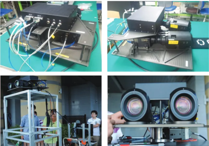
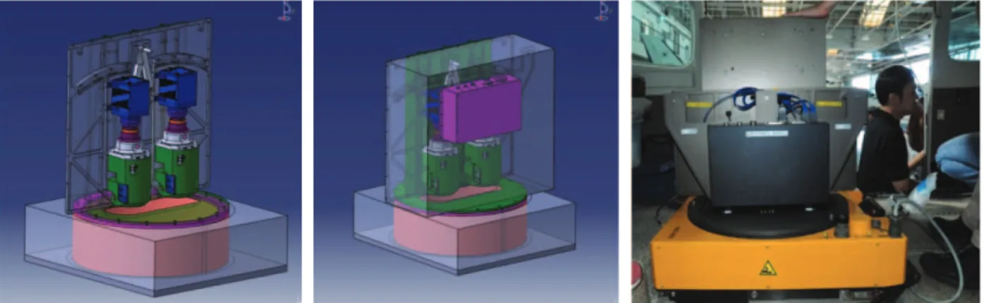
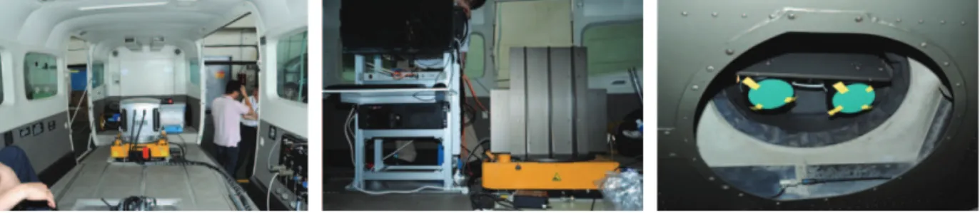
It should be light and small and should consume small power. In order to be used for national program of lunar exploration, electro-optical versatile camera system, called MAEPLE (Multi-Application Electro-Optical Payload for Lunar Exploration), has been designed after the derivation of camera system requirements. A ground model of the camera system has been manufactured to identify and secure relevant key technologies. The ground model was mounted on an aircraft and checked if the basic design concept would be valid and versatile functions implemented on the camera system would worked properly. In this paper, results of design and functional test performed with the field campaigns and air-born imaging are introduced.

Key Words : Lunar Exploration, Stereo Camera, Zoom, Field Campaign, Air-borne Imaging

Received October 10, 2012; Revised November 13, 2012, Revised December 4, 2012; Accepted December 5, 2012.

Corresponding Author: Haeng-Pal Heo ([email protected])

This is an Open-Access article distributed under the terms of the Creative Commons Attribution Non-Commercial License

(http://creativecommons.org/licenses/by-nc/3.0) which permits unrestricted non-commercial use, distribution, and reproduction in

any medium, provided the original work is properly cited.

(2)

an orbitor or a lander of the Moon. It is a versatile electro-optical stereo camera system and its budgets for mass, volume, and power consumption are limited. Zoom mechanism and focus mechanism were decided to be included. In this paper, the design of electro-optical stereo camera system to be installed on a lunar orbitor or a lunar lander is introduced.

Verification process by the field campaigns and air- borne imaging are also introduced.

2. Requirements

MAEPLE had been designed under the assumption that it would be mounted on a lunar orbitor or a landing system on the surface of the moon. Because the platform was not defined yet, most of the external environments and interfaces were defined generally.

Because the first model of the spacecraft for lunar exploration will have many different kinds of payloads and it cannot be so big enough to equip with high performance electro-optic camera system, performance requirements of MAEPLE system would be a moderate level. On the contrary, MAEPLE needs to be very compact and needs to have a few useful functions. For example, it was designed to support both for one dimensional observation and two dimensional observations and it has a compact camera electronics using a CMOS (Complementary Metal Oxide Semiconductor) image sensor. It also has functions to provide images to

zooming-up and zooming-down. Zooming can be very useful when it is operated in an orbitor and also when it is operated in the landing system. Therefore, it can provide pictures with low resolution and wide field of view as well as pictures with high resolution and narrow field of view. Some parts of the optical elements are to be moved for zooming and some other parts of the optical elements are to be moved for re-focusing. The camera system is designed to have on-board image processing capabilities such as non- uniformity correction, pixel rearrangement, image formatting with header information, and real-time image compression. Algorithm for non-uniformity correction is optimized for better image quality (Kong and Lee, 2011). Swath width of the camera system is about 10 km in one dimensional mode before zooming up at the altitude of 100 km. The camera system has capability to keep and manage default mission parameters and they can be updated by command.

3. System Design

The camera system was designed to fulfill the

requirements described in the previous section. The

camera system consists of OM (Optical Module) and

CEU (Camera Electronic Unit). Optical lenses and

lens housing were designed to be compact and to

have good performances. Zoom and refocusing

mechanism were included.

(3)

The motors for zooming and refocusing are controlled by CC (Camera Controller). CC controls two cameras to be operated synchronously with the same parameters. Functional block diagram of the camera system is shown in Fig. 1.

1) Camera system design

The camera system was designed to have moderate level performances because it would not be the only payload on the spacecraft for lunar exploration. High performance camera system cannot be accommodated on such a system because the limited budget of size, weight and power. Instead, it has versatile functional features. It can be operated in push-broom manner at which the detector will behave just like a linear sensor. It can also be operated in a two dimensional imaging mode at which the detector will behave just like an area sensor. The camera system is designed to make it possible to provide images for generating three dimensional target images. Two identical

cameras are controlled by a camera controller and a power supply module. The camera which will be installed on the lunar orbitor will be operated in a push-broom manner. Altitude of the orbitor is assumed to be about 100 km on the lunar orbit. The scanning speed and resultant line rate and data rates are calculated based on that altitude. Scanning speed of the lunar surface will be about 1.5 km per second.

The resolution of the system will be up to a few meters. The resolution and swath width are changeable by command with the help of the zooming mechanism. In order to be installed on the landing system on the moon, the camera is designed to be operated in 2D mode. It can provide still images and the frame rate can be up to 15 frames per second.

Zoom mechanism can also be work in 2D mode to

adjust the field of view and resolution. Imaging

parameters can be adjusted by commands and

operating status information will be transmitted via

MIL-STD-1553 interface with the spacecraft. The

Fig. 1. Block diagram of camera system.

(4)

image data from the detector will be processed, compressed, packetized, and transmitted to the spacecraft in real-time.

2) OM design

The optical module was designed to be dioptrics system and the focal length is about 160 mm before zoom-up. Step motor and supporting mechanical gear and housing were equipped for the zooming and refocusing mechanism. Optical zoom supports up to 5 times and full field of view can be adjusted up to 23

degree. Spectral band is limited to the visible wavelength.

Input radiance to the camera system on lunar orbit is known to be about one third of the radiance in the earth orbit. The f number of the system is decided to be about 5.4 to 6.3 to have good signal to noise ratio while the MTF stays in an acceptable range. As shown in Fig. 2, the optics design consists of four lens groups. The second lens group changes the magnification and the third lens group compensates the change of the focal plane to match with the actual Fig. 3. Block diagram of camera electronic unit.

Fig. 2. Optics design with zoom mechanism.

(a) CEU Configuration (c) Focal Plane Assembly

(b) Camera Controller

(5)

position of the detector.

3) CEU design

Camera electronic unit is designed based on the CMOS image sensor in order to be simple and compact. CEU consists of FPA (Focal Plane Assembly), CC (Camera Controller), and Power Supply Module as shown in Fig. 3. Power supply module has DC to DC converters to provide voltages to CC and FPA. Functional block diagram of CC is shown in Fig. 3. It has MIL-STD-1553 interface to communicate with the spacecraft. It handles command and telemetry from and to the spacecraft.

CC controls two motors which are used for zooming and refocusing. Position of the zoom lenses is to be pre-programmed inside CC and zoom level is to be selected by external commands. Depending on selected zoom level, precise position of the optical elements for re-focusing is to be adjusted.

A CMOS sensor is a core of FPA and the image data from the CMOS is processed in FPA. Gain and offset control, non-uniformity correction, image compression and formatting are executed in FPA and the data is to be transferred to a transmitter in the spacecraft Bus. FPA is controlled by the CC via serial communication. Imaging parameters are transmitted and FPA status information is collected on that interface. Identical two FPAs are controlled by a CC.

Image data flow from the COMS sensor is shown in Fig. 3. The data passes through NUC (Non- Uniformity Correction) function, TDI (Time Delayed Integration) operation, formatting, and compression.

Most of the digital image processing is implemented inside of an FPGA. FPA also has functions to provide the bias voltages to the CMOS together with the control of the CMOS operation.

4. Ground Model Development

In order to secure and verify key technologies for developing the camera system, the designed camera system was implemented into the ground model.

Even though qualification level of the parts used for the ground model was industrial grade, not space grade, basic design and functions were remained.

One of the key parts in the system is an image sensor and CMOS (Complementary Metal Oxide Semiconductor) from Fairchild Imaging was selected.

The sensor is 2K by 2K two dimensional image sensor but it can also be controlled as one dimensional linear sensor with TDI function. The sensor is controlled for image collection in a global shuttering scheme. Line rate control and integration time control can be adjusted independently.

Implemented ground model of CMOS sensor and the focal plane electronics are shown in Fig. 4. The CMOS sensor was mounted on a separated board and control electronics and image buffer was implemented in a different board to minimize the electronic noise and possible thermal issues. The focal plane electronics includes the function of pixel rearrangement, non-uniformity correction and real- time compression. It also supports changing operational mode between one dimensional mode and two dimensional mode. The line rate can be adjusted in one dimensional mode and the frame rate can be adjusted in two dimensional mode and the integration time can also be adjusted to increase the signal to noise ratio.

As shown in Fig. 4, Camera Controller handles

two FPMs and they are synchronized by the camera

controller. EGSE (Electrical Ground Support

Equipment) has been developed to operate and

control the camera system. Image data are coming

from both FPM1 and FPM2 to the frame grabber in

(6)

EGSE. EGSE controls the camera with commands and telemetry via mil-std-1553 interface. It also provides power and 1Hz time clock through LVDS (Low Voltage Differential Signal) interfaces.

Zoom lenses were designed for the optical module.

Two stepping motors were included to control the position of two optical elements for zooming and refocusing. They are controlled by the camera controller based on the commands from EGSE.

Position of the last lens was designed to be moved manually when it was integrated with the focal plane electronics. The focal plane electronics and the optical module have been integrated under a special set-up that used the edge target projected by a integrating sphere in front of a collimator.

When the edge target was appeared on the image displayed by the EGSE, the position of the back focus

lens was adjusted to make best focus on the detector plane. Focus motor was designed to be adjusted whenever the zoom setting was readjusted.

5. Performance Measurement

Before the optical module was integrated with the focal plane electronics, the performance, such as WFE (Wave Front Error) was measured. Both of OM1 and OM2 were measured as the zoom setting was being adjusted. Following Fig. 6 shows the configuration of the equipments for WFE measurement.

After the integration of the camera system, the functional test, radiometric measurement and performance measurement has been conducted. MTF Fig. 4. Ground model of the camera system.

Fig. 5. Ground model of optical module.

(7)

(Modulation Transfer Function) of the camera system has been measured. Edge target was projected to the camera system through the collimator using the integrating sphere. The MTF was measured while the camera was operating in two dimensional mode. As mentioned earlier, the camera system has been

designed to have versatile functions while the performance for the image quality would be kept in a moderate level. In addition to that, because the albedo of the moon was known to be one third of the earth and there would be no high spatial frequency object on the moon, the camera system has been designed to have plenty of signal without pursuing highest image sharpness. Followings are preliminary results of the system performance measurement.

Fig. 7. MTF measurement configuration.

Fig. 8. Radiometric measurement configuration.

Fig. 6. Setup for WFE measurement ((1) interferometer, (2) optical module, (3) flat mirror).

Table 1. Preliminary results of system performance measurements

Zoom Design Measured WFE MTF

position Value(1/l) Mean (1/l) s (1/l)

1 0.021 0.025 4.560E-04 6.2

2 0.037 0.056 6.231E-04 8.3

3 0.048 0.046 3.145E-03 8.6

4 0.050 0.050 6.931E-03 8.3

5 0.039 0.041 7.142E-04 10.4

Zoom Design Measured WFE

position Value(1/ l) Mean (1/l) s (1/l) MTF

(8)

Radiometric characteristics of the camera system, such as linearity, uniformity, signal to noise ratio has been measured. As a result of the radiometric measurement, non-uniformity correction table has been generated. By applying this correction table, non-uniform response of the image sensor has been improved dramatically. Following Fig. 8 and Fig. 9 shows the measurement set-up and some of the results.

Because the camera system is designed to provide stereo imaging capability, it consists of two cameras which are mounted on the platform with a certain amount of convergence angle. In order to produce the stereo images from two cameras successfully, the characteristics of these two camera system should be

almost the same.

Both of them should have the same field of view and ground sample distance at each zoom setup.

Brightness should also be in the similar level to combine them into the stereo images. Fig. 10 shows how these things were checked.

6. Field Campaign

After finishing the test and calibration in the laboratory, it was decided to test the camera system by taking images of targets located in the long distance even though real image target was imaged through a collimator in the laboratory. The camera system and supporting test equipment were taken to Fig. 9. Linearity and signal-to-noise ratio measurement results.

Fig. 10. Checking the characteristics of two cameras for stereo matching.

(9)

the 21st floor of a building where objects in the long distance could be captured with the camera system.

Following Fig. 10 shows the configuration of the camera system and test equipments for the field campaign.

Because the focus of the camera system was adjusted for infinite targets, only real targets located in the distance could be appeared apparently in the image. During the field campaign, both 1D mode operation and 2D mode operation were tested. For 1D mode operation, the camera system was put on top of the rotational stage, where it could be rotated to scan the scenery. Scanning angular velocity was calculated with the object distance, camera focal length, pitch size, and line rate, and so on. For example, for the objects located in the 2 km distance, the resolution of the image data can be calculated as shown below.

GSD (m) = (target distance) ×(pitch size) / (focal

length) = (2 km) ×(6.5 um) / (162.5 mm) = 0.08 m.

Line rate of the camera for 1D operation is decided by the scanning velocity of the platform. In our case, nominal velocity of the airplane is about 260 km/h and resultant line rate is 900 lines/s. IFOV (Instantaneous Field Of View) would be 0.0023 degree and angular velocity of the rotational stage Fig. 11. Field campaign for imaging objects in the distance.

Fig. 12. Collected image from field campaign.

(10)

By performing three times of field campaigns, it was proved that the camera system was well focused to the long distance objects and images were bright enough to fulfill the signal to noise ratio requirement as expected by the signal level analysis. It was also verified that both cameras showed almost the same characteristics that were required for the stereo matching. Functions of EGSE for controlling the camera system and receiving the image data from the camera system were also checked. However, stereo matching could not be tried because it was not the primary purpose of the field campaign and the observations of the targets located in the distance were performed at the same position and different viewing angle of the objects was not performed.

7. Air-borne Imaging

As a next step of field campaign, the camera

angle for stereo matching. First camera was integrated with plus 10 degree of pitch angle tilted and second camera was integrated with minus 10 degree of pitch angle tilted. Therefore, LOS of both cameras would make 20 degree in the flight direction.

Both cameras were mounted on the aircraft such that LOD (Line Of Detector) of the imaging sensors would be perpendicular to the flight direction. Images were taken at the altitude of about 6,000 ft and the aircraft flew at the speed of 140 kn when the cameras were operating. Images were taken at 1D mode and the line rate was controlled to be matched with the ground scanning speed. In addition to the line rate control, minimum exposure time that could satisfy the brightness requirement were set for both cameras because it could provide better condition for image quality. Because the camera system was designed for lunar exploration, it is designed to be sensitive to low illumination at the expense of dull edge response.

Followings were major conditions for the aerial

Fig. 13. Mounting adaptor and mounted configuration on the airplane.

(11)

imaging.

- Airplane Cessna208, flight velocity 140 kn, altitude range 1 ~3 km

- Imaging speed 15 frames/s (in 2D mode), 1000~1500 lines/s (in 1D mode)

As shown in Fig. 14, two cameras were installed on the airplane in the flying direction. First camera was installed to look at the backward direction and the second camera was installed to look at the

forward direction. Both of them were integrated as one body and mounted on the stabilizer. Controlling EGSE was mounted besides the camera system.

When the camera system was taking images in 2D mode, the frame rate was fixed to 15 frames/s and the integration time was adjusted depending on the incoming light intensity. In 1D mode, depending on the altitude of the airplane and flight velocity, the line rate was calculated and adjusted as shown in Table 2.

Fig. 14. Stereo camera mounted on the airplane.

Table 2. Line rate calculation for 1D mode operation

Aircraft velocity 140 kn

259,280 m/h 72.02 m/s

Pitch size (m) 0.0000065

Altitude (m) 2000

Tilt angle (degree) 10

Target distance (m) 2030.85

Zoom x1 x2 x3 x4 x5

Focal length (mm) 32.50 75.00 97.50 130.00 162.50

GSD (m) 0.41 0.18 0.14 0.10 0.08

Line rate (line/s) 177 409 532 709 887

Fig. 15. 2D and 3D images from air-borne imaging.

(12)

so good because they were distorted by the vibration of the aircraft. For the correction of the images distorted by the platform jitter and drift, INS (Inertial Navigation System) information need to be used together with GPS (Global Position System) information that are attached in the image data header. Acquired image data were geometrically corrected and DEM (Digital Elevation Model) was produced. Generation of the stereo images using the images from two cameras is being conducted and following Fig.15 is the preliminary results.

8. Conclusion

Design of the stereo camera system for lunar exploration is introduced briefly. Developed ground model of the stereo camera system was tested in the laboratory. Its functions were also verified by the field campaigns for imaging objects in the distance. It was checked that both camera1 and camera2 were functioning well to produce images with the same characteristics, which makes it easy to conduct stereo matching. Air-born imaging with the stereo camera system showed that its design concept would be proper and applicable for lunar exploration. Collected aerial photograph are being corrected and processed to be merged into the stereo images. Throughout these processes from the design, manufacturing, test at laboratory, field campaign and air-borne imaging, key requirements of the camera system for lunar

initiated and funded by Korea Aerospace Research Institute to be ready for national needs for lunar exploration program in the future.

References

Bhandari, N., 2005. Chandrayaan-1: science goals, Journal of Earth System Science, 114(6): 701-709.

Hisahiro, K., M. Kato, S. Sasaki, Y. Takizawa, and H. Mizutani, 2005. SELENE project status, Journal of Earth System Science, 114(6): 771- 775.

Kong, J.P. and S.J. Lee, 2011. Comparison of correction coefficients for the non-uniformity of pixel response in satellite camera electronics, Korean Journal of Remote Sensing, 27(2):

89-98.

Shim, E.S., 2008. Development status of lunar exploration satellite, Technology Survey of Aerospace Industry and Technology, 2(1): 39-55.

Shin, S.Y., S.Y. Chang, Y.C. Youk, S.S. Yong, and S.H. Lee, 2008. The current payloads development status for the lunar exploration, Journal of Aerospace Technical Trend, 6(1):

74-81.

Sun, H., S. Dai, J. Yang, J. Wu, and J. Jiang, 2005.

Scientific objectives and payloads of Chang’

E-1 lunar satellite, Journal of Earth System

Science, 114(6): 789-794.

수치

Fig. 2.  Optics design with zoom mechanism.
Fig. 5.  Ground model of optical module.
Fig. 7.  MTF measurement configuration.
Fig. 10.  Checking the characteristics of two cameras for stereo matching.
+4

참조

관련 문서