• 검색 결과가 없습니다.

Evaluation of Damage Tolerance under Mode II Deformation of Composite Structure for Tilting Train Carbody

N/A
N/A
Protected

Academic year: 2021

Share "Evaluation of Damage Tolerance under Mode II Deformation of Composite Structure for Tilting Train Carbody"

Copied!
6
0
0

로드 중.... (전체 텍스트 보기)

전체 글

(1)

II II II II

Damage tolerance under Mode II deformation of carbon fabric/epoxy composite, which was

applicable to a tilting train carbody, was investigated by a Mode II interlaminar fracture test. The

specimens were made of plain woven fabric with epoxy and a delamination at one end was made

by inserting Teflon film with the thickness of 12.5 or 25.0 . The equation for mode II

interlaminar fracture toughness was suggested based on the effective crack length from the

compliance of load-displacement curve. Mode II interlaminar fracture behaviors were investigated

through an optical travelling scope and a scanning electron microscope.

(2)

120

20

35

(unit : mm)

4.2

Fig. 1 Configuration of Mode II interlaminar fracture

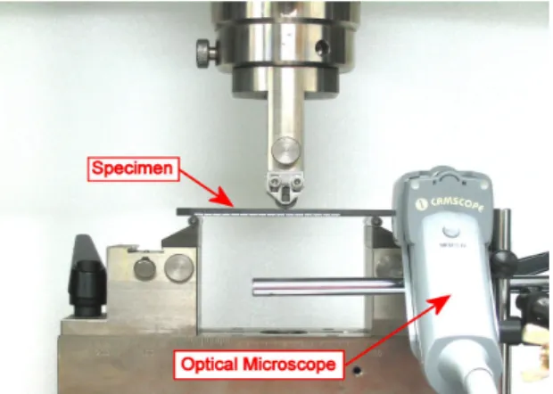
specimen Fig. 2 Test set-up for evaluating Mode II interlaminar

fracture toughness

(3)

(1)

(2)

(3)

δ (4)

δ

(5)

δ (6)

δ

(4)

CF3327/Epoxy_12.5

Displacement (mm)

0 1 2 3 4 5

Load (N)

0 300 600 900 1200 1500

NL 5% offset NL

5% offset

② ②

③ ③

④ ④

⑤ ⑤ ⑤

⑤ ⑥ ⑥ ⑥ ⑥

Fig. 3 Several locations for investigating the crack propagating behaviors

Fig. 4 Microphotographs showing crack propagation on the edge of the specimen

(5)

Fig. 5 SEM photographs of fractured surfaces for the specimen with 12.5 thick inserter

Fig. 6 SEM photographs of fractured surfaces for the specimen with 25.0 thick inserter
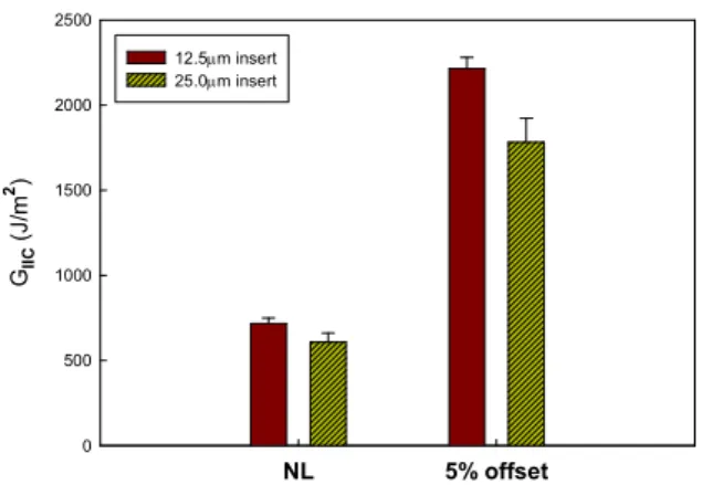
(6)

NL 5% offset G

IIC

( J /m

2

)

0 500 1000 1500 2000 2500

12.5µm insert 25.0µm insert

Fig. 7 Comparison of mode II interlaminar fracture toughness

by varying with insert thickness

수치

Fig.  1  Configuration  of  Mode  II  interlaminar  fracture
Fig.  4  Microphotographs  showing  crack  propagation  on  the  edge  of  the  specimen
Fig.  5  SEM  photographs  of  fractured  surfaces  for  the  specimen  with  12.5 thick  inserter
Fig.  7  Comparison  of  mode  II  interlaminar  fracture  toughness  by  varying  with  insert  thickness

참조

관련 문서

For this, the amount of deformation of welded specimens has been measured and compared, which fabricated under four kinds of welding conditions such as

The purpose of this study was to evaluate the microleakage of composite resins(Filtek ™ Z250), resin-reinforced glass ionomer cements (Fuji II LC ® ), and traditional

▶ See lecture note P99-104 and P108 for the flexural and shear strengths of composite slab-on- stringer deck.... ▶ Transverse Stiffeners and Shear-Dominant Failure

• Accumulated microscopic damage develops into a crack or other  macroscopic damage

Typical trace of pacemaker potentials in current clamping mode (A) and spontaneous inward pacemaker currents in voltage clamping mode at a holding potential of -70 mV

These optimum design requirements include: i) a minimum number of tube turns for a PHP operable in top heat mode, ii) the use of R-123 as working fluid with 50 % charging

(a) Bottom emission structure (b) Double-sided emission structure. (d) Top emission structure - II (c) Top emission

Now return to ply stresses from CLPT, and how they can cause failure For laminate, have found ply stresses and strains on ply-by-ply basis Try to use these to assess failure..