Vol.14, No.4, pp.25-31 (2020)
Mechanical Properties Prediction by Manufacturing Parameters for Braided Composites
Myungjun Kim
1,†1Department of Aviation Maintenance Engineering, Silla University
Abstract
The development of manufacturing technology for braided composites has led to farther extension of the applications in aerospace structures. Since the mechanical characteristics of braided composites are affected by various materials and manufacturing parameters, it is important to determine the parameters required to appropriately design the braided composite structures. In this study, we proposed a geometric model of RUC (repeating unit cell) for 2D braided composites, and predicted the mechanical properties according to the change of fiber volume fraction, fiber filament size, braiding angle, and gap between adjacent yarns by the yarn slicing technique and stress averaging method. Finally, we analyze the characteristics of mechanical properties according to each manufacturing parameter of the braided composite material.
Key Words: Braided Composites, Manufacturing Parameters, Repeating Unit Cell, Fiber Volume Fraction, Gap between Adjacent Yarns
1. Introduction
CFRP (carbon fiber reinforced plastic) composite materials have been applied to various aerospace structures due to their high specific stiffness and strength, and good fatigue resistance.
On the other hand, the use of textile composites is increasing because of their superior out-of-plane delamination and impact characteristics and higher flexibility compared to traditional unidirectional fiber reinforced composite materials. Also, the textile composite material is showing high potential as a major material in the aerospace field due to the advancement in manufacturing technology [1-3].
Mechanical properties of textile composites can be designed based on various manufacturing parameters. In case of the 2D braided composite materials, a kind of textile composite material, fiber yarns are intersected according to the braiding angle such that that the mechanical properties can be adjusted more freely. Accordingly, various studies have been conducted on the effective stiffness prediction method considering various manufacturing parameters of textile composite materials.
An analytical approach based on CLT (classical laminate theory) was mainly used in the early studies on the effective stiffness prediction of textile composite materials. Chou and Ishikawa proposed three analytical models based on classical laminate theory for two-dimensional plain weave composite
materials: a mosaic model, a fiber undulation model, and a bridging model [4]. Ko et al. proposed a FGM (fabric geometry model) based on the classical laminate theory, and predicted the effective stiffness of the 3D braided composite materials through the energy analysis technique [5]. Pastore and Gowayed proposed a modified FGM method and predicted the behavior of textile composites [6]. Yang et al. proposed FIM (fiber inclination model) to define a unit cell model of textile composite materials as a set of inclined unidirectional composite layers [7].
There are two numerical methods of predicting the effective stiffness of textile composite materials: finite element analysis of a RUC (repeating unit cell) and a fiber yarn discretization method. Foye defined the inhomogeneous finite element of the concept of sub-cell in the RUC, and predicted the mechanical properties of plain weave, satin weave, and braided composite materials [8]. Xu et al. predicted effective properties for biaxial and triaxial braided composite materials through finite element modeling and analysis at the macro and micro levels [9]. Naik, Masters, and Ifju selected representative manufacturing parameters for the triaxial braided composite materials and defined a geometric model for the RUC. The curved and straight fiber yarns were discretized into yarn slices, and the effective stiffness of the RUC was predicted through the stiffness averaging technique [10]. Also, Naik defined geometric models for various textile composite materials such as plain weave, satin weave, and braided composite materials, and predicted the Received: Jun. 16, 2020 Revised: Jul. 17, 2020 Accepted: Jul. 22, 2020
† Corresponding Author
Tel: +82-51-999-5986, E-mail: [email protected]
Ⓒ The Society for Aerospace System Engineering
effective mechanical properties of each material through the fiber yarn discretization method and the stress averaging method [11, 12].
Iterative finite element modeling and analysis are required to predict effective mechanical properties based on various manufacturing parameters through numerical method. However, since the textile composite materials has a more complicated fiber yarn structure than the unidirectional composite material, finite element modeling and analysis require enormous time, effort, and cost. On the other hand, the fiber yarn discretization method is very effective in repeatedly predicting the effective stiffness.
In this study, we proposed a modified repeating unit cell model of the 2D biaxial braided composite material based on the geometric model presented by Naik [12]. The modified RUC considered the gap between adjacent fiber yarns to model more realistic fiber yarn shape and structure. In addition, the effective stiffness of the braided composite materials was predicted based on the proposed geometric model of the RUC, and the characteristics of mechanical properties with respect to the change of various manufacturing parameters were analyzed.
To predict the effective stiffness, the fiber yarn discretization method and the stress averaging method were applied. Also, the predicted mechanical properties were compared with the results of Naik's model, and the mechanical properties according to the fiber yarn gap ratio, fiber yarn size (filament count), overall fiber volume fraction, and braiding angle.
2. Repeating Unit Cell
2.1 Definition of Repeating Unit Cell (RUC)
Textile composite materials exist in two forms according to the fiber yarn architecture: weaving and braided composites.
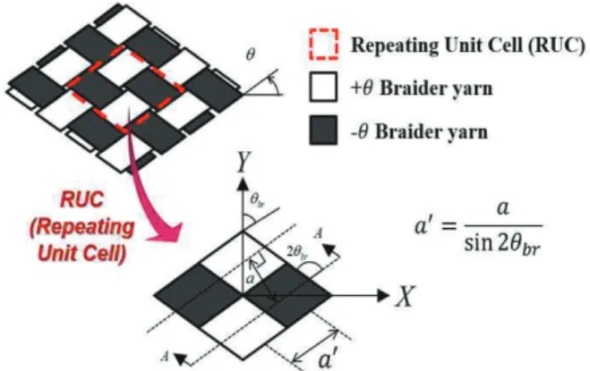
The woven composite material has a structure in which two fiber yarns are orthogonal to each other, and exists in two forms according to the cross pattern of fiber yarns: plain weave and satin weave. The braided composite material has a structure in which fiber yarns are not orthogonal but cross according to the braiding angle, and exists in two forms according to the number of fiber yarns: biaxial and triaxial braided composites. The biaxial braided composite material has a structure consisting of two fiber yarns like the plain weave composite material, however, the mechanical properties of each direction can be designed freely through the braiding angle. In this study, we defined a geometric model for the RUC of the 2D biaxial braided composite material and predicted the effective mechanical properties. The RUC of the biaxial braided composite material is defined as shown in Fig. 1, and the braiding angle is defined clockwise based on the Y-axis of the global coordinate system.
Fig. 1 Repeating Unit Cell of Braided Composites 2.2 Geometry Model of RUC
2.2.1 Definition of Manufacturing Parameters Naik defined the geometric models for the RUC of plain weave and braided composite materials, and predicted the effective stiffness based on the fiber yarn discretization method [12]. Sine curve and straight functions were used to model the lenticular yarn cross-section shape. In addition, it was assumed that there was no gap between adjacent fiber yarns. However, in the case of the actual textile composite material, there is a gap between the fiber yarns with an arbitrary size as shown in Fig. 2 [13].
In this study, we defined a modified geometric model for the repeating unit cell of the biaxial braided composite materials based on Naik's model considering the gap between fiber yarns.
The manufacturing parameters and braiding parameters considered for predicting effective stiffness include braiding angle (), fiber volume fraction (), fiber packing density ( ), fiber filament diameter ( ), fiber filament count ( ), yarn spacing ( ), and gap between adjacent yarns ( ). Yarn spacing refers to the distance between the centers of different fiber yarns in the cross-section of the RUC, and the gap between adjacent yarns is as shown in Fig. 2.
Fig. 2 Microscopic Cross-section of Textile Composites [13]
2.2.2 Definition of Geometry Model of RUC
A geometrical model for the cross-section ‘A-A’ of Fig. 1 is defined as shown in Fig. 3. The cross-sectional shape of the fiber yarn is as shown in Fig. 4, and it is composed of curved and straight portions. The coordinate system and geometrical variable () for the cross-section 'A-A' are related as shown in Eq. 1 to the variable () for the cross-section of the fiber yarn.
Fig. 3 Cross-section geometry of RUC for 2D biaxial braided composites
Fig. 4 Cross-section geometry of yarn
=
sin 2 (1) Geometric parameters for the fiber yarn cross-section and the RUC can be obtained based on the manufacturing parameters defined for the braided composite material. The fiber volume fraction () , one of the manufacturing parameters, can be defined as Eq. 2 through other manufacturing variables, and the cross-sectional area of the fiber yarn () can be defined as Eq.
3.
=2
(2)
=
4 (3) Where, H is total thickness of the RUC, which is twice the yarn thickness.
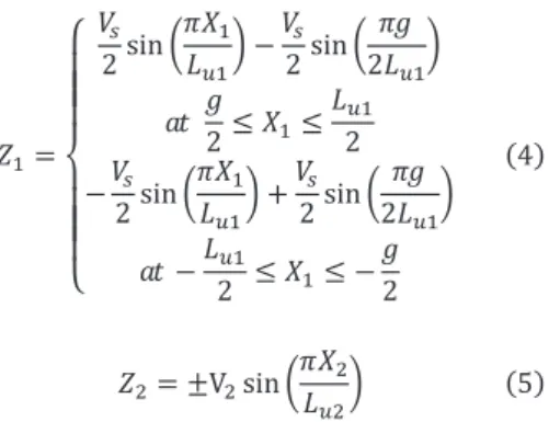
The cross-section of the fiber yarn is close to a lenticular shape, and can generally be defined through a sine function. In this study, the shape function of the curved portion is defined as Eq. 4 and 5 using the sine function.
=
⎩⎪
⎪⎪
⎨
⎪⎪
⎪⎧ 2 sin
− 2 sin
2
2 ≤ ≤
2
−
2 sin
+
2 sin
2
−
2 ≤ ≤ − 2
(4)
= ±Vsin
(5) Where, and are the vertical coordinate axes of the upper and lower curved portions of the fiber yarn cross-section, respectively. denotes the vertical distance between the centers of the fiber yarn cross-section, which is assumed to be equal to the thickness of the fiber yarn. and denote the length of the curve portion for the fiber yarn path and the length of the curve portion in the fiber yarn cross-section, respectively. and denote the vertical lengths of the upper and lower curved portions of the fiber yarn cross-section, respectively, and determined as shown in Eq. 6 and 7.
=V
2 1 − sin
2 (6)
= V− =V
2 1 + sin
2 (7) The fiber yarn cross-sectional area can be calculated through integration as shown in Eq. 8 based on the geometric parameters in Fig. 3 and 4. Also, lengths of the curved and straight portions,
, and can be obtained by using Eq. 3 and 8.
= −
+ 1 −
(8) +1
− 1
2(− ) sin
2 +
cos
2
3. Effective Stiffness Prediction
3.1 Fiber Yarn Discretization Method
To predict the effective stiffness of the braided composite material, we applied the yarn discretization method to the defined RUC model. Also, we obtained the effective properties of the RUC through a stress averaging technique that averages the local stiffness of the fiber yarn slices over the entire volume of the RUC. We used the iso-strain assumption for the total strain of the RUC to predict the local strain of each yarn slice.
The definition of the local coordinate system for the fiber yarn slice is as shown in Fig. 5. The local coordinate system is
defined by the in-plane angle with respect to the X axis of the global coordinate system and the out-of-plain angle with respect to the X-Y plane. The is determined by the braiding angle (), and the is determined by the differential value of the vertical position of the fiber yarn slice with respect to the longitudinal position . In the case of a straight portion, all out-of-plane angles are defined as zero. Since the resin filled between the fiber yarn regions is an isotropic material, the in- plane and out-of-plane angles are defined as = = 0.
Fig. 5 Coordinate system of yarn slice 3.2 Effective Stiffness of RUC
The effective stiffness of the braided composite material can be predicted by averaging the stiffness of the fiber yarn slices and resin in the repeating unit cell over the total volume as shown in Eq. 9.
= ([][][])
(9)
Where, denotes the effective stiffness matrix for the global coordinate system of the RUC, and [] denotes the stiffness matrix of the mth material slice for the local coordinate system. denotes a volume fraction for each slice, and []
denotes a coordinate transformation matrix with respect to the direction angles (, ) of each slice.
3.3 Influence of Gap between Adjacent Yarns
Effective stiffness was predicted using the proposed geometrical model of the 2D biaxial braided composite material.
The mechanical properties of fiber yarn and resin applied to predict the effective stiffness were as shown in Table 1, and manufacturing parameters were as shown in Table 2. To calculate the effective stiffness, the MATLAB in-house code was used.
Table 1 Mechanical properties of yarn and resin [12]
Material
(GPa)
(GPa)
(GPa)
Yarn 144.80 11.73 5.52 0.23 0.30
Resin 3.45 3.45 1.28 0.35 0.35
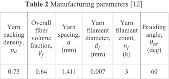
Table 2 Manufacturing parameters [12]
Yarn packing density,
Overall fiber volume fraction,
Yarn spacing,
(mm)
Yarn filament diameter,
(mm)
Yarn filament
count,
(k)
Braiding angle,
(deg)
0.75 0.64 1.411 0.007 3 60
Since the size of the gap between adjacent fiber yarns is an arbitrary value, a specific assumption is required. In this study, the predicted results of mechanical properties were evaluated while changing the gap ratio (/) from 0 to 0.1. When the gap ratio is 0, it means that the fiber yarns are completely in close contact with each other without any gap between the yarns, which is the same as the assumption of the repeating unit cell model proposed by Naik.
Figure 6 shows the geometric parameters according to the gap ratio of the biaxial braided composites. As the gap increased, the length of the curved portion ( ) gradually increased, while and have little changes. In addition, as the gap increases, the fiber volume fraction gradually decreases because the volume of the resin in the RUC increases.
Fig. 6 Geometric parameters for gap ratio of yarns Figures 7~9 show the mechanical properties with respect to the gap ratio of the fiber yarns. To compare and evaluate the change of properties, each value was normalized to the maximum value.
As shown in Fig. 6, both the tensile and shear modulus decrease linearly because the fiber volume fraction has a relatively linear decrease as the fiber yarn gap increases. In addition, since the fiber yarn is placed close to the X-axis in the global coordinate system as the braiding angle is 60°, the stiffness with respect to the X-axis is relatively largely changed.
In the case of Poisson's ratio, as the gap increased, the in-plane Poisson’s ratio gradually decreased while the out-of-plane Poisson’s ratio increased. Table 3 shows the results of the comparison between the predicted effective stiffness of the
biaxial braided composite and the predicted values through Naik's model. In the case of this study’s proposed model, the length of the fiber yarn gap () was assumed to be 5% of the yarn spacing ( ). The mechanical property prediction results through the two models showed a difference within 5%.
Fig. 7 Normalized elastic modulus for gap ratio
Fig. 8 Normalized shear modulus for gap ratio
Fig. 9 Normalized Poisson’s ratio for gap ratio
Table 3 Results of effective stiffness prediction Mechanical
properties
Naik’s model [12]
Present model (/ = 0.05)
(GPa) 45.25 43.52
(GPa) 11.20 10.84
(GPa) 11.15 10.81
(GPa) 24.93 23.90
(GPa) 4.72 4.50
(GPa) 6.05 5.65
1.23 1.22
0.22 0.23
-0.01 -0.02
3.4 Influence of Manufacturing Parameters
The mechanical properties of braided composites can be designed based on various manufacturing parameters. The manufacturing parameters include fiber volume fraction, fiber yarn size, fiber yarn spacing, braiding angle, gap between adjacent fiber yarns, etc. Therefore, it is important to select appropriate manufacturing parameters to design the mechanical properties of the braided composite material. However, it takes a lot of cost and time to compare and evaluate the mechanical properties through repeated specimen tests with the various manufacturing parameters.
In this study, we performed parametric studies on the fiber yarn size (), fiber volume fraction (), and braiding angle ( ) using the proposed RUC model of the biaxial braided composite. The range of fiber yarn size was considered as 2k to 18k, the range of fiber volume fraction was considered as 0.45 to 0.65 and the range of braiding angle was considered as 15°
to 75°. The variations of mechanical properties according to each parameter were as shown in Fig. 10~12.
Fig. 10 Variation of mechanical properties with fiber yarn size ()
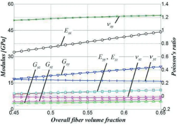
Fig. 11 Variation of mechanical properties with fiber volume fraction ()
Fig. 12 Variation of mechanical properties with braiding angle ()
As the fiber yarn size increased, , , , and
gradually decreased at the same rate, whereas increased non-linearly. increases because the cross-sectional area of the fiber yarn increases as the fiber yarn size increases, and the thickness of the RUC increases under the constant fiber volume fraction. The increases until the fiber yarn size reached 10k then decreases slightly. On the other hand, , , and
were relatively unaffected by the increase in fiber yarn size.
The elastic modulus and increased linearly with increasing fiber volume fraction with showing the largest increase rate. The modulus of elasticity in the other direction also increased slightly. In the case of Poisson's ratio,
shows a characteristic that increases linearly like and , however, there is slight change in the Poisson's ratio in other directions. The shows a very slight decrease. These results show that as the fiber volume fraction increases, the stiffness in the X-axis direction close to the fiber yarn longitudinal direction increases.
Since the braiding angle is a major parameter that determines
the longitudinal direction of the fiber yarn, there is a significant change of mechanical properties compared to the case of fiber yarn size and fiber volume fraction. When the braiding angle is 45°, since the biaxial braided composite material has the identical yarn architecture as the plain weave composite material, the mechanical properties in the X and Y axis directions have the same values. In the case of , it shows the largest value when the braiding angle is 62°, and the out-of- plane elastic modulus, , and , are not significantly affected by the change in braiding angle.
4. Conclusions
In this study, we proposed a modified geometric model for the repeating unit cell of a biaxial braided composite material and conducted parametric studies to predict the effective mechanical properties with respect to the manufacturing parameters. The proposed RUC model considered the gap between adjacent fiber yarns based on the model presented by Naik [12]. First, the effective stiffness of the braided composite material was predicted with respect to the size of the gap by assuming a gap ratio ( / ) in the range of 0-10%. The characteristics of mechanical properties according to the size of the gap were analyzed, and the stiffness in the X-axis direction was significantly affected when the braiding angle was assumed to be 60°. Second, mechanical properties according to the fiber yarn size, fiber volume fraction, and braiding angle were predicted and analyzed. As the fiber yarn size increased, the elastic modulus in the thickness direction tended to increase. In the case of the fiber volume fraction, the stiffness in the X-axis direction was significantly affected, similar to the gap effect. In the case of the braiding angle, the effective mechanical properties showed a significant change because it is the parameter that determines the longitudinal direction of the fiber yarn. If the method of predicting the effective mechanical properties of the braided composite material proposed in this study is applied to the aerospace structural design field, the weight reduction effect can be derived by optimal designing of the material to meet the structural requirements.
References
[1] Niu, M. C., Composite Airframe Structures, Conmilit Press Ltd., Hong Kong, 1992.
[2] Niranjan K. Naik, Woven fabric composites, Technomic Publishing Co., Inc., 1994.
[3] Brian N. Cox, "Handbook of Analytical Methods for Textile Composites," NASA Contractor Report 4750, Contract NAS1-19243, 1997.
[4] Chou, T-W., Ishikawa, T., "Analysis and Modeling of Two- Dimensional Fabric Composites," Composite Materials Series 3, Textile Structural Composites, pp. 210-264, 1989.
[5] Ko, F. K., Pastore, C. M., Lei, C. and Whyte, D. W., "A
Fabric Geometry Model for 3-D Braid Reinforced FP/AI- Li Composites," International SAMPE Metals Conference:
Competitive Advances in Metals/Metal Processing, Cherry Hill, NJ, 1987.
[6] Pastore, C. M. and Gowayed, Y. A.: "A Self-Consistent Fabric Geometry Model: Modification and Application of a Fabric Geometry Model to Predict the Elastic Properties of Textile Composites," Journal of Composites Technology and Research, JCTRER, Vol. 16, No. 1, pp. 32-36, Jan.
1994.
[7] Yang, J-M., Ma, C-L., and Chou, T-W., "Fiber Inclination Model of Three-Dimensional Textile Structural Composites," Journal of Composite Materials, Vol. 20, pp.
472-484, September 1986.
[8] Foye, R. L.: "Finite Element Analysis of the Stiffness of Fabric Reinforced Composites," NASA CR-189597, National Aeronautics and Space Administration, Hampton, Virginia, Feb. 1992.
[9] Lei Xu, et al., "Prediction of material properties of biaxial and triaxial braided textile composites," Journal of Composite Materials, Vol. 46, No. 18, pp.2255-2270, 2012.
[10] Naik, R. A., Ifju, P. G. and Masters, J. E., "Effect of Fiber Architecture Parameters on Deformation Fields and Elastic Moduli of 2-D Braided Composites," Journal of Composite Materials, Vol.28, pp.656-681, 1994.
[11] Naik, N. K. and Ganesh, V. K., "Prediction of On-Axes Elastic Properties of Plain Weave Fabric Composites,"
Composites Science and Technology, Vol. 45, pp. 135-152, 1992.
[12] Rajiv A. Naik, "Analysis of Woven and Braided Fabric Reinforced Composites," NASA Contractor Report 194930, Contract NAS1-19399, 1994.
[13] Home Made Composite, http://www.composites. ugent.be /home_made_composites/what_are_composites.html.
![Table 3 Results of effective stiffness prediction Mechanical properties Naik’s model [12] Present model (/ = 0.05) (GPa) 45.25 43.52 (GPa) 11.20 10.84 (GPa) 11.15 10.81 (GPa) 24.93 23.90 (GPa) 4.72 4.5](https://thumb-ap.123doks.com/thumbv2/123dokinfo/5101334.326631/5.892.472.805.799.1028/table-results-effective-stiffness-prediction-mechanical-properties-present.webp)