Mobile Target Speed Estimation in Urban Environments with Adaptive Power Control
Hyeon-Cheol Lee*, Jong Tae Lee*, Sang Burm Ryu*, Eun Su Kang*
도시환경에서 적응전력제어를 이용한 이동국 속도추정
이현철*, 이종태*, 유상범*, 강은수*
ABSTRACT
The adaptive power control of Code Division Multiple Access (CDMA) systems for communications between User Equipments (UEs) with a link-budget based Signal-to-Interference Ratio (SIR) estimate which has distance information is applied to three inner loop power control algorithms. The speed estimation performances of these algorithms with their consecutive Transmit-Power-Control (TPC) ratios are compared to each other, and it is concluded that the speed can be estimated using the TPC ratio information of Consecutive TPC Ratio Step-size Closed Loop Power Control (CS-CLPC) and Fixed Step-size Power Control (FSPC).
Key Words : speed estimation, adaptive power control, link-budget, SIR, Inner loop power control
*Payload Electronics Team, Korea Aerospace Research Institute ([email protected])
접수일자 : 2016년 03월 24일, 수정완료일자 : 2016년 03월 28일, 최종게재확정일자 : 2016년 03월 30일
I. Introduction
The communication system of an User Equipment (UE) requires a mobile wireless network to share data between UEs. One communication network protocol that may be used is Code Division Multiple Access (CDMA). CDMA differs from both Frequency Division Multiple Access (FDMA) and Time Division Multiple Access (TDMA) in that it uses the same frequency for multiple users.
Since all users utilize a single frequency, the signal from each UE may interfere with other UEs' receivers [1].
This is referred to as the near-far effect. To eliminate the near-far effect in CDMA systems, the transmission signal power from every UE must be the same as the signal power at the receiver. This technique of controlling the magnitude of the transmission power according to the distance between the UE and the Base Station (BS) is officially termed power control. It equalizes the received power and eliminates the near-far effect, though it is subject to such complications as path loss, shadowing, multi-path fading, etc.
This power control technique is differentiated into open loop power control and closed loop power control. The
closed loop power control is further divided into inner loop power control and outer loop power control. The inner loop power control is responsible for adjusting the power transmitted to maintain the received Signal-to-Interference Ratio (SIR) at the BS at a level equal to that at the SIRtarget. The outer loop power control is responsible for setting the SIRtarget based on the service requirement.
Conventional SIR estimates [2] consider only the transmission power and the link-gain, but this paper takes into account the link-budget, which has more realistic parameters including distance information than the link-gain. Using the SIR estimate that reflects the link-budget, speed estimation [3] is introduced based on a Consecutive Transmit-Power-Control Ratio (CTR) [4].
The proposed speed estimation method is applied to three algorithms, and the results are compared.
This paper is organized as follows: The inner loop power control is described in Section Ⅱ. The concept of the link-budget based SIR estimate is introduced in Section Ⅲ, followed by description of simulation environments in Section Ⅳ. Section Ⅴ gives details of the speed estimation. The simulation results are analyzed in Section Ⅵ. Finally, conclusions are drawn in Section Ⅶ.
Ⅱ. Inner Loop Power Control
In CDMA, the process of inner loop power control occurs as follows: In the reverse link direction (from the UE to the BS), the transmission power information goes to the BS. At the BS, the SIRtarget and the received SIR are calculated from the transmission power, the link-gain, and the noise power. Based on these factors, the BS sends a Transmit-Power-Control (TPC) command to each UE at rate of 1500Hz or Sample Time (TS) (= 0.667 ms) in the forward link direction (from the BS to the UE). This power equalization increases the maximum communication number between UEs and consequently eliminates the near-far effect. These procedures [2], [4] are represented in (1) and (2).
∙ (1)
where Pi(t) is the transmission power, δi(t) is the power control step-size, and TPCi(t) is the TPC command for the ith UE at time t.
(2)
where SIRtarget,i(t) (=SIRtarget(t) here) is the target SIR and SIRi(t) is the received SIR for the ith UE at time t.
Sign is a signum function. In cases in which the received SIR at the BS is greater than the SIRtarget(t), the TPCi(t) is set to -1 and the transmission power of the ith UE has to be decreased. On the other hand, if the received SIR is less than the SIRtarget(t), the TPCi(t) is 1 and the transmission power must be increased.
Ⅲ. Link-budget Based SIR
The conventional SIR estimate of the ith UE in CDMA is described as follows :
≠
(3)
where Gi(t) is the link-gain between the ith UE and the connected BS, and Pi(t) is the transmission power from the ith UE. Gji(t) is the link-gain between the jth UE and the BS to which the ith UE connects. Equation (3),
however, does not have distance information, therefore, SIRi(t) can not be measured by distance step.
This paper introduces the link-budget based SIR as
≠
(4)
where PR,i is the received power from the ith UE. PR,ji is the received power from the jth UE with the BS to which the ith UE connects. The received power is affected by factors including the free space loss [5] which has distance information and gaseous path loss [6] varied by humidity. Speed estimation can be possible with distance per TS and SIRi(t) is measured with PR,i by distance variation.
The power delivered to the receiver [7] is :
∙∙ ∙ (5)
where GT,i, PT,i, GR,i, LF(Di), and LG(Di) are the transmission antenna gain, the transmission power, the receive antenna gain of the ith UE, the free space loss, and the gaseous path loss, respectively (the component loss is ignored here.). Di is the distance between the ith UE and the BS in kilometers.
(6)
F is the frequency in GHz and the reference distance d0
corresponds to a point located in the far field of the antenna. This is taken to be 1km for large cells, 100m for microcells, and 1m for indoor channels. Xρ denotes a zero-mean Gaussian random variable with standard deviation ρ in decibels. n depends on the frequency, antenna heights, and propagation environment. n is 2 in free space, n can be lower than 2 in urban streets, and n is larger when obstructions are presents. The specific attenuation due to dry air and water vapor from sea level to an altitude of 5km can be estimated by (7).
∙ (7)
P.676-5 of [6] shows equations of γO (attenuation for dry air) and γw (attenuation for water vapor). These attenuations are dependent on σ, the water vapor density (g/m3) specified in Table 1 from P.836-3 of [6]. The
bigger the σ is, the larger the attenuation is.
Table 1. Water vapor density at different seasons and regions
Jan. April July Oct.
Coast 5 10 20 10
Inland 5 5 10 5
Ocean 20 20 20 20
The noise power [7] is :
∙∙ (8)
where k is the Boltzmann constant (1.38 x 10⁻²³ J/K), T is the temperature in Kelvin, and B is the equivalent bandwidth in Hz.
Ⅳ. Simulation Environments
This section presents a simulation of the speed estimation using (4). The frequency, the temperature, the pressure, the water vapor density, and the bandwidth are set to 2.0GHz, 288K, 1013hPa, 20 (Summer in Coast), and 5MHz, respectively. In Fig. 1, five UEs are arranged and Dis are set to 25m, 50m, 75m, 100m, and 125m. The parameters needed to statistically described path loss due to large-scale fading for urban environments are d0=0.1km, n=2.7, and ρ=11.6dB. The antenna gain of each UE is set to 0dB, as is the antenna gain of the BS.
UE1-UE5 complete their power control by FSPC so that each transmission power shown in Table 2 is different.
Then, UE1, which is 125m away from the BS, starts to move outward. It moves at five different speeds and measures the CTR at each speed. SIRtarget is set to the transmission power of UE3 on this simulation. This simulation applies one UE movement and outward/inward direction only.
Fig. 1 Simulation formation
Table 2. Initial condition of UE1 – UE5
PT[dB] GT[dB] GR[dB] Di[m]
UE1 +6.347 0.0 0.0 125
UE2 +3.564 0.0 0.0 100
UE3 +0.000 0.0 0.0 75
UE4 -5.003 0.0 0.0 50
UE5 -12.84 0.0 0.0 25
Ⅴ. Speed Estimation
There are several algorithms addressing inner loop power control, including CTR Step-size Closed Loop Power Control (CS-CLPC) [4], Adaptive Step-size Closed Loop Power Control (AS-CLPC) [8], Fixed Step-size Power Control (FSPC), etc.
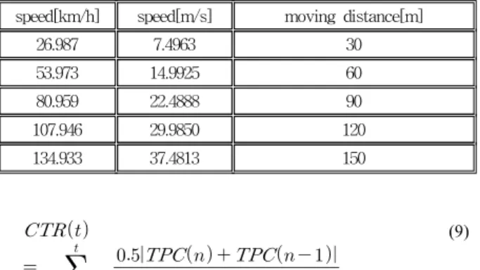
This section investigates changes in transmission power for the above three algorithms with the link-budget based SIR. UE1 moves outward for 6000*TSms (the number of the sample = 6000) at the five different speeds listed in Table 3; 26.99km/h, 53.97km/h, 80.96km/h, 107.95km/h, and 134.93km/h. As UE1 moves away, the three inner loop power control algorithms alter the transmission power to compensate for the distance between BS and UE1. A faster mobile is likely to receive more consecutive TPC command than a slower one.
Therefore, average of CTR on certain period can be used to reflect user speed. Equation (9) [4] measures the CTR as follows:
표 3. UE1 moving distance for 4.0sec(=6000*TSms) speed[km/h] speed[m/s] moving distance[m]
26.987 7.4963 30
53.973 14.9925 60
80.959 22.4888 90
107.946 29.9850 120
134.933 37.4813 150
(9)
where m=t if t < w and m=w if t => w. w is the maximum size of the window average.
2.1 CS-CLPC
Patachaianand et al. [4] introduced the CS-CLPC algorithm, where the step-size is adjusted as shown in (10).
∙
(10)
where α, β, and CTRmax are constants.
2.2 AS-CLPC
Kim et al. [8] suggested the AS-CLPC algorithm. This algorithm adapts its step-size based on TPC history. The step-size is given by (11).
∙ (11)
where K and L are positive real constants with ranges of 1<K and 1<L<2.
2.3 FSPC
In this simulation, the algorithm uses a fixed step-size.
Ⅵ. Simulation Results
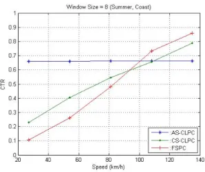
Five different speeds are measured with CTR, and the relationships are shown in Fig. 2 - Fig. 4 according to three different window sizes. The CS-CLPC and FSPC algorithms show a linear relationship between speed and CTR. Therefore, using the CS-CLPC or FSPC, the speed of the vehicle can be measured by mapping the information from CTR. The AS-CLPC algorithm, however, deviates from linearity. In addition, the same results are obtained with different window sizes.
Fig. 2 CTR vs. UE1 speed at window size 3
Fig. 3 CTR vs. UE1 speed at window size 8
Fig. 4 CTR vs. UE1 speed at window size 12
Ⅶ. Conclusion
This paper introduced a speed estimation of three different inner loop power control with consecutive TPC ratios which use the link-budget based SIR in the CDMA communication systems between UEs. It was concluded that linear relationship exists between speed and Consecutive TPC Ratios, and that UE speed can be estimated using the Consecutive TPC Ratios of the CS-CLPC and FSPC algorithms.
References
[1] J. Perez-Romero, O. Sallent, R. Agusti, and M. A. Diaz- Guerra, Radio Resource Management Strategies in UMTS, John Wiley & Sons, New York, 2005.
[2] R. Patachaianand and K. Sandrasegaran, "Performance comparison of adaptive power control in UMTS," Int. Conf.
Wireless Broadband and Ultra Wideband Commun., Sydney, Australia, 2007, pp. 81-85.
[3] R. Patachaianand and K. Sandrasegaran, "User speed estimation techniques for UMTS," Electronics Letters, vol.
43, no. 19, pp. 1036-1037, Sep., 2007.
[4] R. Patachaianand and K. Sandrasegaran, "Consecutive transmit power control ratio aided adaptive power control for UMTS," Electronics Letters, vol. 43, no. 5, pp. 55-56, March, 2007.
[5] B. Sklar, "Rayleigh fading channels in mobile digital communication systems part I: Characterization," IEEE Communications Magazine, pp. 90-100, July 1997.
[6] ITU-R Recommendations and Reports 2004, Sep. 2004.
[7] D. Roddy, Satellite Communications, Prentice Hall, New Jersey, 1989.
[8] J. H. Kim, S. J. Lee, and Y. W. Kim, "Performance of single-bit adaptive step-size closed-loop power control scheme in DS-CDMA system," IEICE Trans. Commun., vol.
E81-B, no. 7, pp. 1548-1552, July 1998.
Hyeon-Cheol Lee(이 현 철)
․1983.03 ~ 1987.02 : B.S. degree, Dep’t of Electronic Engineering, Kyungbook National University, Rep.
of Korea
․1987.03 ~ 1989.02 : M.S. degree, Dep’t of Electronic Engineering, Kyungbook National University, Rep. of Korea
․1989.02 ~ 1996.07 : UAV Team, Agency for Defense Development, Rep. of Korea
․1996.09 ~ 2001.12 : Ph.D. degree, Dep’t of Electrical Engineering, Texas A&M University, U.S.A.
․2002.02 ~ 2003.02 : Post Doctorate, Dep’t of Computer Science, Texas A&M University, U.S.A.
․2003.03 ~ present : Payload Electronics Team, Korea Aerospace Research Institute, Rep. of Korea
<Research of Interest> : SAR, Satellite Communication
Jong Tae Lee(이 종 태)
․1990.03 ~ 1994.02 : B.S. degree, Dep‘t of Electronic Engineering, Chungnam National University, Rep.
of Korea
․1994.03 ~ 1996.02 : M.S. degree, Dep’t of Electronic Engineering, Chungnam National University, Rep. of Korea
․2000.04. ~ present : Payload Electronics Team, Korea Aerospace Research Institute, Rep. of Korea
<Research of Interest> : Satellite Communication, Space Engineering
Sang Burm Ryu(유 상 범)
․1992.03 ~ 1996.02 : B.S. degree, Dep’t of Electronic Engineering, Daejon National University of Technology, Rep. of Korea
․2000.03 ~ 2001.02:M.S. degree, Dep’t of Electronic Engineering, Chungbuk National University, Rep. of Korea
․2006.02 ~ 2010.08 : Ph.D. degree, Dep’t of Electronic Engineering, Chungbuk National University, Rep. of Korea
․2011.01 ~ present : Payload Electronics Team, Korea Aerospace Research Institute
<Research of Interest> : Spaceborne Remote Sensing, Satellite Communication
Eun Su Kang(강 은 수)
․1998.03 ~ 2006.02 : B.S. degree, Dep’t of Electronic Engineering, Kyungbook National University, Rep.
of Korea
․2006.03 ~ 2008.02:M.S. degree, Dep’t of Electronic Engineering, Kyungbook National University, Rep. of Korea
․2008.02 ~ 2012.03 : Ph.D. degree, Dep’t of Electronic Engineering, Kyungbook National University, Rep. of Korea
․2002.05 ~ present : Payload Electronics Team, Korea Aerospace Research Institute, Rep. of Korea
<Research of Interest> : Satellite Communication, Digital communication, Microwave