* ** ***
Numerical and Experimental Investigation of Thermal Behavior of a Radiation Heater for Flip-Chip Bonders
Sanghyun Lee, Ho Sang Kwak, Chang Soo Han, Do Hyun Ryu
Key Words : Flip Chip Bonder( ), Radiative Heater( ), Thermal Modeling(
), Numerical Analysis( ), High-Speed Heat-up( ), Thermal Experiment( ).
Abstract
A numerical and experimental study is made of thermal behavior of a hot chuck which is specially designed for flip-chip bonders. The hot chuck consists of radiant heat sources and a heated plate of very high conductivity, which is for achievement of high-speed heat-up. A simplified numerical model is developed to simulate unsteady thermal behavior of the heated plate. Parallel experimental work is also conducted for a prototype of the hot chuck. Based on the experimental data, the numerical model is tuned to improve the reliability and accuracy. Design analysis using the numerical model is conducted. The results of numerical computations illustrate that the radiant heater system adopted in this study satisfies the key design requirements for a high-performance hot chuck.
1.
.
.
(flip chip bonder)
.
(hot chuck)
. (solder)
.
µ m
*
E-mail : [email protected]
TEL: (054)467-4229 FAX: (054)467-4472 **
***
1645
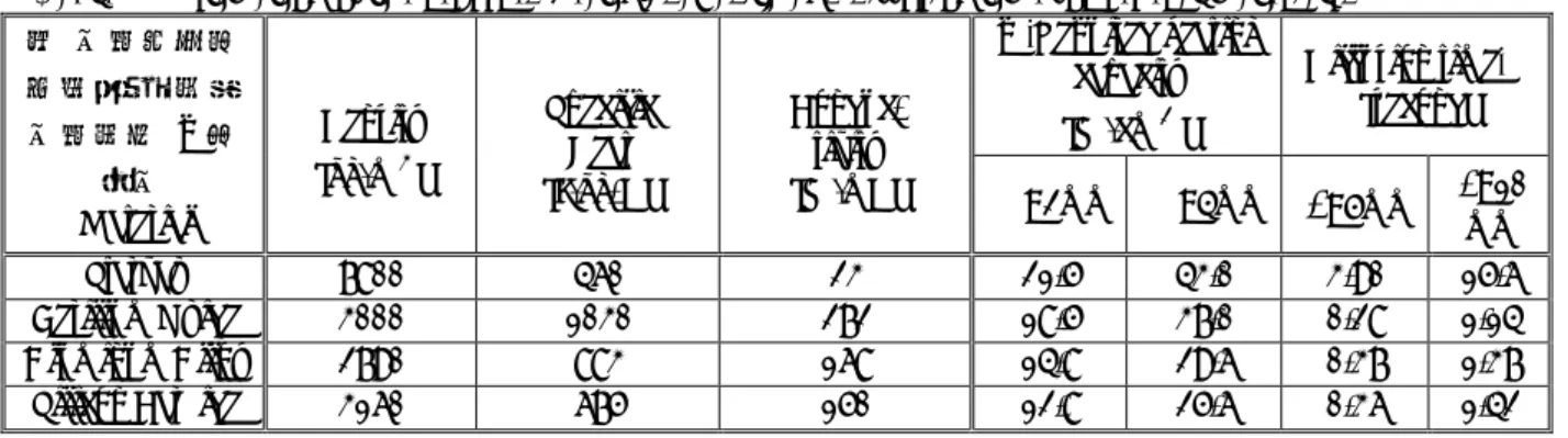
Table 1 Estimation of the required heating capacity and diffusion time for several materials.
.
.
.
2.
2.1
. 30 /s
. .
. , Cp,
k , A
Q . k
(lumped capacity approach)(1)
dt Q A dT
C
p = (1).
C s dt
dT 30
o/
(2)
dt A dT A C
q ''
=Q
p (3)2mm, 4mm 30 /s
Table 1 . 2mm
12W/cm2 .
20W/cm2 (2).
.
1 .
. 4
. Table 1
.
2.2
. ,
1 .
q'',Required heating capacity [W/cm2]
Diffusion time [second]
q"
Material
Density [kg/m3]
Specific Heat [J/kg-K]
Conduc- tivity
[W/mK] =2mm =4mm
l
=5mml
=10mm
Starvax 7800 460 23 21.5 43.0 3.90 15.6
Berilium Oxide 3000 1030 272 18.5 37.0 0.28 1.14
Aluminum Alloy 2790 883 168 14.8 29.6 0.37 1.37
Silicon Carbide 3160 675 150 12.8 25.6 0.36 1.42
1 . .
.
. .
1 , 800W (3)
. Fig. 1 .
1 1 .
. 800W
82.8W/cm2 . 2mm
70%
. Fig. 2 Fig. 1
. P1 P3
P1, P2,
P3 .
. . l
.
=
l
2/
(4)( =
k / C
p ) .l
Table 1 .
.
Fig. 1 Schematic diagram of the heating system.
Fig. 2 Top-view of the heating tool. The shadow indicates the area heated by radiation.
. Table 1 Starvax
.
.
.
.
(SiC) .
3.
3.1
1647
, , .
.
''
q
i ''q
o BuoyantFlow
Heating Tool y x
z
Radiative heating from halogen lamps
x y z
''
q
i ''q
o BuoyantFlow
Heating Tool y x
z
Radiative heating from halogen lamps
x y z
Fig. 3 A simplified model to predict unsteady thermal behavior of heating tool.
. Fig. 3 .
, ,
.
"
q
iq
o"
.
t
C
pT
= 22+
22+
22z
T y
T x
k T
(5)x, y, z , , .
z
k T q
i''( x , y ) at z
=0
(6a)z
k T q
0''( x , y ) at z
=( y x , )
(6b)a
q
i"
"
q
o.
a L
v h
1
2
= L a
h
v (7)
. (5) z
2 .
t a T
C
p =k 22+
22y
T x
T
+q
i" q
o"
(8)3.2
"
q
iq
o"
."
q
i3 .
,
.
) ,
''
( x y
A f Q
q
i = (9)Q A
1 . f
(1-f) .
280-320JC
"
"
"
0
q
convq
emitq = +
(10)q
''conv =h ( T
sT )
(11-1)q
''emit =T
s4 (11-2)3 (11-1) h
(4) .
h
=Nu ( k / d )
(12)Nu
=CRa
m (13)x Td g
Ra =
3/
(14)4 / 1 , 54 .
0 =
= m
C for Ra = 10
4~ 10
73 / 1 , 15 .
0 =
= m
C for Ra = 10
7~ 10
11d , g
, T ,
. (11-2) L
0.85 -
(Stefan - Boltzmann) 5.67×10 8W/m2·k4 .
(8)
2 (5).
.
.
Fig. 4 Time-dependent variation of the temperature at the center of heating tool.
4.
3 Fig.1
.
. Q=1600W , f 0.1, 0.15, 0.3, 0.6, 1.0
10%, 15%, 30%, 60%, 100%
. 1/2 0.5mm
46x84 . Fig. 4
(P1) 400oC
.
.
.
15% 30JC
/s .
30% 55.8JC/s
.
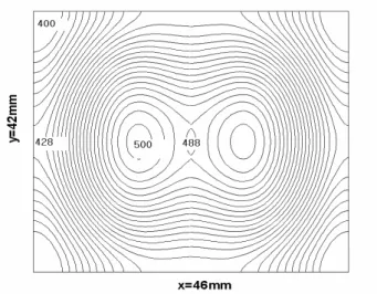
. Fig. 5
f=0.15 P2 500JC
Fig.5 Temperature distribution on the heating tool when the temperature at P2 reaches at 500oC.
f=0.15.
1649
.
. 100JC
.
.
. Fig.6
Fig.2 3
.
.
280W , f=0.18 .
20%
80%
.
.
P3
.
Fig. 6 Comparison of numerical results and experimental results.
.
.
.
5.
.
30oC/s
.
.
.
(1) A. Bejan, 1987, Heat Transfer,John Wiley & Sons , pp.146-148.
(2) Watlow, 2002,Your Heat Solution Resources,
COR-LC-0601, Watlow Eletric Manufacturing
Company.
(3) http://www.osram.co.kr/.
(4) Y. A. Cengel, 1999, Heat Transfer; A practical approach, McGraw-Hill.
(5) S. V. Patankar, 1980, Numerical Heat Transfer and Fluid Flow, McGraw-Hill.