• 검색 결과가 없습니다.

Finite Element Analysis for Fracture Resistance of Fiber-reinforced Asphalt Concrete

N/A
N/A
Protected

Academic year: 2021

Share "Finite Element Analysis for Fracture Resistance of Fiber-reinforced Asphalt Concrete"

Copied!
7
0
0

로드 중.... (전체 텍스트 보기)

전체 글

(1)

Finite Element Analysis for Fracture Resistance of Fiber-reinforced Asphalt Concrete

유한요소해석을 통한 섬유보강 아스팔트의 파괴거동특성 분석

Baek, Jongeun 백`종`은 Member·Pavement Research Center, Seoul Metropolitan Government·Corresponding Author (E-mail : [email protected] )

Yoo, Pyeong Jun 유`평`준 Member·Korea Institute of Civil Engineering and Building Technology Researcher (E-mail : [email protected])

1. INTRODUCTION

Recently potholes have been recognized as a critical issue in asphalt pavements because most of all, they can lead to traffic accidents. In Seoul, 41,313 potholes were developed in 2012 and the number of potholes got increased due to the

increase of old asphalt pavements and climate changes (Han 2013). During the last 5 years, 94,746 of potholes had appeared in Korean express highways and the number of traffic accidents related to the potholes was reported to 1,032 (Kim 2014).

Int. J. Highw. Eng. Vol. 17 No. 3 : 77-83 JUNE 2015 http://dx.doi.org/10.7855/IJHE.2015.17.3.077

ABSTRACT

PURPOSES : In this study, a fracture-based finite element (FE) model is proposed to evaluate the fracture behavior of fiber-reinforced asphalt (FRA) concrete under various interface conditions.

METHODS : A fracture-based FE model was developed to simulate a double-edge notched tension (DENT) test. A cohesive zone model (CZM) and linear viscoelastic model were implemented to model the fracture behavior and viscous behavior of the FRA concrete, respectively.

Three models were developed to characterize the behavior of interfacial bonding between the fiber reinforcement and surrounding materials. In the first model, the fracture property of the asphalt concrete was modified to study the effect of fiber reinforcement. In the second model, spring elements were used to simulated the fiber reinforcement. In the third method, bar and spring elements, based on a nonlinear bond-slip model, were used to simulate the fiber reinforcement and interfacial bonding conditions. The performance of the FRA in resisting crack development under various interfacial conditions was evaluated.

RESULTS : The elastic modulus of the fibers was not sensitive to the behavior of the FRA in the DENT test before crack initiation. After crack development, the fracture resistance of the FRA was found to have enhanced considerably as the elastic modulus of the fibers increased from 450 MPa to 900 MPa. When the adhesion between the fibers and asphalt concrete was sufficiently high, the fiber reinforcement was effective. It means that the interfacial bonding conditions affect the fracture resistance of the FRA significantly.

CONCLUSIONS : The bar/spring element models were more effective in representing the local behavior of the fibers and interfacial bonding than the fracture energy approach. The reinforcement effect is more significant after crack initiation, as the fibers can be pulled out sufficiently.

Both the elastic modulus of the fiber reinforcement and the interfacial bonding were significant in controlling crack development in the FRA.

Keywords

Fiber-reinforced asphalt (FRA), finite element analysis, fracture behavior, cohesive zone model

Corresponding Author : Baek, Jongeun

The Pavement Research Center, Quality Inspection Office Devision, Seoul Metropolitan Government 131, Taebong-ro, Seocho-gu, Seoul 137-900, Korea

Tel : +82.2.3462.6718 Fax : +82.2.3462.6710 E-mail : [email protected]

International Journal of Highway Engineering http://www.ksre.or.kr/

ISSN 1738-7159 (print) ISSN 2287-3678 (Online)

Received May. 17. 2015 Revised May. 18. 2015 Accepted Jun. 2. 2015

(2)

Various construction and repair methods were developed to control potholes. For example, hydrated lime additives or anti-stripping agents were used to reduce moisture damage of asphalt mixtures (Hicks 1991, Sebaaly et al. 2004, Yang et al.

2008). Fiber reinforcement made of recycled polyethylene terephthalate (PET) was developed to enhance the tensile strength and toughness of conventional asphalt mixtures (Yoo and Al-Qadi, 2013). Fiber-reinforced asphalt (FRA) mixtures with the recycled PET fibers had 30% higher post- peak toughness. It was found that the toughening mechanism of the fibers relies on the characteristics of fibers, binders, and aggregates. Thus it needs to develop appropriate material models which can reflect these material characteristics on pavement design and analysis.

Classical linear elastic fracture mechanics (LEFM) has some limitations on simulating the fracture behavior of quasi-brittle materials such as concrete due to relatively large fracture process zone ahead of crack front. Cohesive crack model was proposed in early 1960’ s to overcome the limit of the LEFM and was extended to predict a fracture behavior of concrete. Since then, a cohesive zone model (CZM) has widely been used to predict crack development for cement and asphalt concretes. An intrinsic CZM was developed to characterize a fracture behavior of asphalt concrete (Paulino et al. 2004, Song et al. 2005, 2006). Furthermore, the CZM was incorporated into a three-dimensional pavement model to predict a fracture behavior of asphalt concrete overlay under moving vehicular loading (Baek and Al-Qadi 2008, 2009). The use of the fiber-reinforcement can result in significant changes in the fracture behavior of the FRA because of the effect of interfacial behavior between fibers and surrounding materials and orientation and content of the fibers. Hence, it needs to develop a proper approach to address the effect of the fiber reinforcement on the fracture behavior of the FRA.

Hence, this study developed a fracture-based finite element (FE) model to understand the fracture behavior of the FRA concrete. A couple of friction models were incorporated to characterize the interfacial behavior between the fiber reinforcement and surrounding materials. The performance of the FRA in resisting against crack development under various interfacial conditions was evaluated.

2. FE MODEL DEVELOPMENT 2.1. Geometry and boundary condition

To examine the effect of fiber-reinforcement on the fracture behavior of the FRA, it was simulated a double-edge notched tension (DENT) test. The specimen for the DENT test is 100 mm long and 50 mm wide and has a notch which is 1 mm wide and 5 mm long as shown in Fig. 1. Due to the geometric symmetry of the specimen with respect to its center line, the half of the specimen was modeled in this study by applying y-axis symmetric boundary conditions (u

x

≠0, u

y

= 0, θ

xy

= 0) onto the center line. A tensile force was applied at a constant rate of 0.77 mm/min to the specimen through a displacement boundary condition to monitor the applied force, i.e. a displacement-controlled test (u

x

=0 = 0, u

x

=100mm

= 0.77 mm/min).

The finite element model for the DENT test was mainly consisted of 479 linear rectangular plain stress elements for a far-field zone from the notch and 609 linear triangular plain stress elements close to the notch. In addition, 2D cohesive elements were inserted in the middle of the specimen to model crack development during the test. It was assumed that a crack will be initiated at the tip of the notch and develop along the center line of the specimen, perpendicular to the loading direction.

2.2. Fiber reinforcement

This study used three approaches to consider the behavior

of the fiber reinforcement used in the FRA: Fracture property

modification, spring element addition, and bar-spring element

addition. The first approach, fracture property modification, is

to modify the fracture property of the FRA which is used as

an input parameter in the CZM. This approach is a simple

Fig. 1 Geometry of a Double-Edge Notched Tension (DENT) Test

(3)

and practical way of reflecting the effect of fiber reinforcement on global fracture behavior because it does not increase the degree of freedom of the FE model. However, it is hard to examine local failure modes and fiber characteristics such as fiber orientation and shape directly.

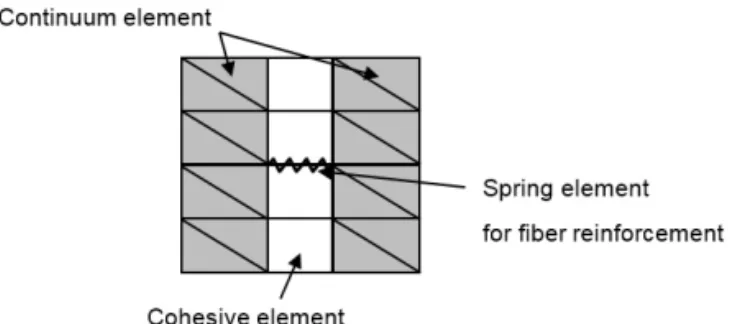
The second approach, spring element addition, is to add zero-length spring elements onto the potential fracture process zone corresponding to the location of fiber reinforcement as shown in Fig. 2. Stiffness of the spring elements represents additional crack resistance of the RFA due to the fibers. The number of spring elements depends on the content of the fibers. In this study, eight fibers are assigned perpendicular to the failure line. This approach, however, does not consider the shape of the fibers.

The third approach, bar/spring addition, is to add bar and spring elements to represent the behaviors of fibers and interfacial bonding condition between the fibers and asphalt concrete, respectively. The shape of the fibers can be

characterized by means of length and cross sectional area of the bar elements. In this study, eight fibers were added along the predefined crack line as shown in Fig. 3. The length of the fibers ranges from 2.5 mm to 3.5 mm which is appropriate for the FRA with 13 mm of nominal maximum aggregate size (NMAS) based on the previous research (Yoo et al.

2009). Corresponding cross section of the fibers is 1.5 mm wide and 0.3 high. During the compaction of the FRA, fibers can be distorted randomly so that the fibers were arbitrarily rotated. This random orientation was simulated by controlling the direction of the fibers subjectively as shown in Fig. 3(b).

The interfacial bonding between fiber reinforcement and asphalt concrete can be quantified by the stiffness of the spring elements, so called the bond-slip model. A set of spring elements was used to define vertical and horizontal bonding between a fiber and asphalt concrete. The spring elements are governed by a nonlinear force-displacement relation. With the increase of displacement, for example, tension force increases up to its elastic limit, decreases after its peak and converses to zero as shown in Fig. 4. Also, various bond-slip conditions can be applied. This approach is able to model fiber characteristics and friction condition more Fig. 2 Spring Element Approach Concept

(a) Bar-Spring Elements Connection

(b) Bar Elements Location Fig. 3 Bar-Spring Element Approach

Fig. 4 The Bond-Slip Model Used for Spring Elements

Approach Fracture property Spring element Bar/spring element

Feature Equivalent fracture property of FRA

Spring element for fiber

Bar element for fiber, spring element for interfacial behavior Fiber

reinforcement N/A Stiffness Shape, modulus Boundary

condition N/A Completed

bonded

Stiffness (Bond-slip) Table 1. Comparison of Three Approaches to Model Fiber

Reinforcement

(4)

realistically. The main characteristics of the three approaches are briefly summarized in Table 1.

2.3. Material property

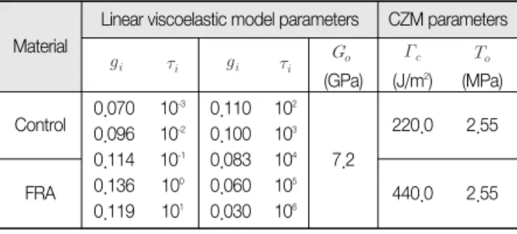
The bulk behavior of the FRA was characterized using a linear viscoelastic model. The generalized Maxwell model, one of the linear viscoelastic model, formulated by the Prony series expansion was used to represent bulk behavior of the FRA. The Prony series parameters for the asphalt concrete at -10℃ were adapted from a previous study done by Baek and Al-Qadi (2009). Since the contribution of fiber reinforcement in bulk behavior is not significant, the FRA was assumed to have the same bulk property of the unreinforced (control) asphalt concrete. Since the fracture property of the FRA was not measured, the fracture energy of the FRA was assumed to have two times of that of the unreinforced asphalt concrete;

the tensile strength of the FRA was assumed to be the same as the unreinforced asphalt concrete. However, the bulk and fracture property of the FRA needs to be obtained from laboratory tests in the further study. The Prony series (Eq. 1) and CZM (Eq. 2) parameters of the unreinforced asphalt concrete and FRA are summarized in Table 2.

where is shear relaxation shear modulus at time (GPa), is instantaneous shear modulus at (GPa), is dimensionless Prony series parameters for shear modulus, and N is number of Prony series parameters.

where is fracture energy (J/m

2

), is cohesive strength (MPa), is critical separation at failure (m).

3. EVALUATION OF FIBER REINFORCEMENT 3.1. Fiber Reinforcement Model Comparison

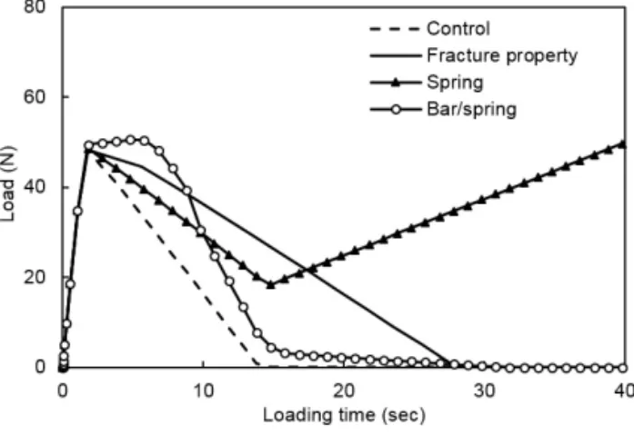
In order to examine the effect of the three fiber reinforcement approaches on the performance of the FRA, induced load variations with time were obtained from the DENT test simulation. Fig. 5 shows the comparison of the load-time curves for the three fiber reinforcement models. In this test, loading time and displacement are equivalent because of the constant displacement control of the DENT test. The control one indicates unreinforced asphalt concrete.

The unreinforced asphalt concrete had the peak load of 49.4 N at 1.7 sec; then load decreased gradually and became zero at 14 sec, meaning that the specimen was broken into two parts completely and no force can be carried out. Fig. 6(a) shows an example for tensile stress distribution in the DENT test for the control one. Tensile stress was concentrated at a vicinity of the notch and crack was initiated; once the crack developed through the specimen completely, no stress was developed.

When the FRA was modeled with the fracture property modification approach, the same amount of maximum load was developed at the same time (the solid line in Fig. 5).

However, due to higher fracture energy of the FRA ( of the RFA and control one is 440 J/m

2

and 220 J/m

2

, respectively), area under the load-time curve after the peak load becomes larger than that of the control one. It means that the fiber reinforcement enhanced the fracture resistance of the asphalt concrete. Hence, once the fracture property of the FRA is determined, this fracture property modification approach can be easily implemented for other FE model by increasing the fracture energy of the FRA.

When the spring element approach or bar/spring element approach is used for the FRA, a significant change was found in its fracture behavior compared to the control one. The major difference is that the fiber reinforcement can take a part of loads during crack development, e.g., after 14 sec. Also, the peak load increased and corresponding loading time was delayed for the bar/spring element approach. The changes mainly result from the spring stiffness in the spring element approach; and the stiffness of the bar and spring elements in the bar/spring element approach. Fig. 6(b) demonstrates one case for the bar/spring element approach. During crack development, some parts of the asphalt concrete were already (1)

(2)

Table 2. Material Property of the Unreinforced (Control) Parameters

Material

Linear viscoelastic model parameters CZM parameters

(GPa) (J/m

2

) (MPa) Control 0.070

0.096 0.114 0.136 0.119

10

-3

10

-2

10

-1

10

0

10

1

0.110 0.100 0.083 0.060 0.030

10

2

10

3

10

4

10

5

10

6

7.2

220.0 2.55

FRA 440.0 2.55

(5)

cracked, but the rest of the asphalt concrete where fiber reinforcement was inserted was not fractured fully due to the fiber reinforcement. Compared to the fracture property modification approach, hence, it may be more accurate to characterize the fracture behavior of the FRA, considering the effect of fiber reinforcement on local and global fracture behavior. Therefore, it is suitable to use the bar/spring element approach to investigate the effect of the fiber reinforcement on the fracture behavior of the FRA.

3.2. Effect of Modulus of Fiber Reinforcement on Fracture Resistance

Using the bar/spring element approach, it was evaluated the effect of the modulus of the fiber reinforcement on the fracture resistance. The nonlinear bond-slip model was used for the spring elements to characterize the interfacial bonding condition between fibers and asphalt concrete. Since the fibers can be made of various materials such as Polypropylene (PP) and PET, the elastic moduli, E of the fibers were assumed in the three levels of 450 MPa, 900 MPa, and 3500 MPa. Fig. 7 shows the load-time curves for the three cases. The initial slope of the control one is almost same as that of the FRA. It means that most of tensile stress was carried out not by the fibers but by the asphalt concrete before crack was initiated. So, the reinforcing effect of the fibers before crack initiation was not exhibited yet.

On set of the crack initiation right after the peak load was dropped, the reinforcing effect of the fibers was shown. The peak load of the control one was 48.0 N at 2.0 sec. When the fibers with E of 450 MPa were added, the peak load increased slightly to 50.5 N (+5.2%) and corresponding time delayed from 2.0 sec to 4.9 sec and the area under the curve was expanded by 7.3% compared to that of the control one. It resulted from that the fibers absorbed excessive tensile stress which could be developed in unreinforced asphalt concrete.

So, crack initiation in the FRA could be delayed.

As the modulus of the fibers increased, the peak load and the area under the curve of the FRA increased. For example, the peak load of the FRA was 65.0 N (+35.4%) and 70.0 N (+45.8%) and the area increased to 37.6% and 47.8% when Fig. 5 Comparison of Load-Time Variations of the FRA in the

Three Approaches

(b) FRA with the Bar/Spring Approach Fig. 6 Tensile Stress Distribution in the DENT

(a) Unreinforced (control) Asphalt Concrete

Fig. 7 Comparison of Force-Time Variations of the FRA with

Three Levels of Modulus

(6)

the modulus of the FRA was 900 MPa and 3500 MPa, respectively. It is noticed that the reinforcing effect of the strong fibers with E of 3500 MPa was not considerably enhanced compared to that of the fibers with E of 900 MPa.

With the increase of the modulus of the fibers, the more tensile force was transferred from the fibers (bar elements) to the spring elements linking to the fibers and the asphalt concrete. The spring elements were stretched out faster, meaning that interfacial bonding was broken and the fibers began to be pulled out. So, the strong fibers could not absorb more tensile stress as expected.

3.3. Effect of Interfacial Bonding Conditions on Fracture Resistance

Using the bar/spring element approach, it was evaluated the effect of interfacial bonding conditions on the fracture resistance of the FRA. Bonding and friction conditions between fiber reinforcement and surrounding materials are dependents on texture and materials of the fiber reinforcement. Three bond-slip models incorporated in the spring elements were used to represent these interfacial bonding conditions. In this analysis, the modulus of the fiber reinforcement was fixed as 900 MPa.

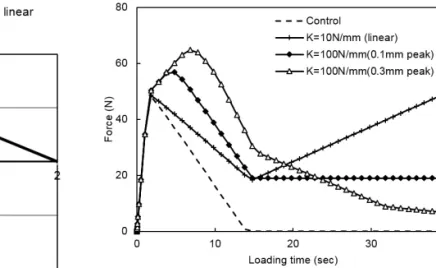
Fig. 8 shows the three bond-slip models. The first case had a constant spring constant (K) of 10 N/mm; the second case had nonlinear stiffness in that the force increases at a constant rate of 100 N/mm until 0.01 mm, and keeps the same as 1.0 N until 0.4 mm, and decreases to zero at 2.0 mm; the third case had also nonlinear stiffness of K of 66.7 N/mm until

0.03 mm, after then K of - 5.4 N/mm until 0.4 mm, and K becomes zero. This force-displacement relationship is the same in compression and tension.

When the first bond-slip model was used, the peak force was the same as the control one because the fibers could carry out only a few loads at the lower level of displacement.

After the peak load, i.e., crack initiation, the fibers absorbed more loads with proportional to frictional force. After the asphalt concrete is fully fractured, only the fibers could resist against the fracture and the fracture resistance kept increasing as the frictional force became higher. It resulted from that no plastic or fracture behavior was considered in the fiber so that the fiber could resist against fracture as long as it is attached to the asphalt concrete. Hence, it needs to better to model the fiber with a plastic or fracture model and/or to allow interfacial debonding between the fibers and asphalt concrete.

The second case represents higher adhesion of 1 N, i.e., friction between the fiber and asphalt concrete at the beginning of the fiber movement until 0.01 mm of displacement. In this case, the peak load was increased by 15% due to higher interfacial bonding. After crack initiation, a constant fracture resistance was developed due to a constant interfacial bonding at 0.1 mm to 0.4 mm of displacement. It can happen when the fiber has rough texture which can hold surrounding materials more firmly and longer.

In the third case, the interfacial bonding was assumed to have the highest adhesion at the beginning, but lost it relatively quickly as slipping occurs between the fiber and asphalt concrete. Because of the highest adhesion, the

Fig. 8 Three Bond-Slip Models

Fig. 9 Comparison of Post-Peak Behaviors of the FRA with the

Three Bond-Slip Models

(7)

fracture resistance or strength of the FRA was the greatest among the three cases at the beginning; however the resistance diminished at a fast rate. Therefore, the interfacial bonding conditions affect the fracture resistance of the FRA significantly. However, since it is very difficult to obtain the interfacial bonding property of the FRA, the bond-slip model parameters can be indirectly obtained from a small scale pull- out test.

4. CONCLUSION

This study developed three numerical approaches to simulate the behavior of fiber reinforcement used in asphalt concrete. The first approach was to modify the fracture property of the asphalt concrete, equivalent fracture energy of the FRA. The second and third approaches were to use additional structural elements: Bar elements for the fiber reinforcement and spring elements for the interfacial bonding conditions between the fibers and surrounding materials.

The double-edge notched tension (DENT) test was simulated to examine the three fiber reinforcement approaches. The fracture property approach was easy to be implemented into a global pavement model, but unable to represent local fracture behavior and to consider friction conditions. The bar/spring element approach could represent the shape of fiber reinforcement and interfacial bonding conditions by means of the geometry of the bar elements and stiffness of the spring elements, respectively.

From the bar/spring model, it was found that the fiber reinforcement effect was obvious after crack initiation as the fibers absorbed the excessive tensile stress in the asphalt concrete. The toughness of the FRA was enhanced with the increase of the elastic modulus of the fibers and interfacial bonding between the fibers and asphalt concrete as well.

In the next step of this study, the FE models need to be validated using experimental results and calibrated to find proper material properties such as interfacial bonding stiffness, rotation angle, and so on.

ACKNOWLEDGEMENTS

The results presented in this study are partly supported by Korea Institute of Construction and Building Technology (KICT) under an ongoing project entitled as “Pothole-Free Asphalt Pavement System.”

BIBLIOGRAPHY

Baek, J. and Al-Qadi, I. L. (2008a) Finite element modeling of reflective cracking under moving vehicular loading, Proceedings of ASCE ’ s 2008 Airport and Highway Pavements Conference, Bellevue, W.A., pp.74-85.

Baek, J. and Al-Qadi, I. L. (2009). Reflective cracking: Modeling fracture behavior of hot-mix asphalt overlays with interlayer systems, Journal of the Association of Asphalt Paving Technologists, Vol. 78, pp.638-673.

Han Y.J. (2013) Lessen potholes as mines on roads, Safe Today, Ministry of Public Safety and Security, November 5, 2013.

Hicks, R. G., (1991) Moisture damage in asphalt concrete, NCHRP Synthesis of Highway Practice 175, Transportation Research Board, Washington, D.C.

Kim, S.K. (2014) Traffic accidents related to pothole in express highways are 1,032 cases in the last 5 years, Sisa Times, Sep. 3, 2014 at http://m.sisatime.co.kr/news/articleView.html?

idxno=41919

Paulino, G. H., Song, S. H., and Buttlar, W. G. (2004) Cohesive zone modeling of fracture in asphalt concrete, Proceedings of the 5th International RILEM Conference-Cracking in Pavements: Mitigation, Risk Assessment, and Preservation, Limoges, France, pp.63-70.

Sebaaly, T.P., Hajj, E.Y., and Johnston, D. (2004) Effectiveness of anti-strip additives for bituminous mixtures, International Journal of Pavements, Vol. 3, No. 2, pp.50-62.

Song, S. H., Paulino, G. H., and Buttlar, W. G. (2005) Simulation of mode I and mixed-mode crack propagation in asphalt concrete using a bilinear cohesive zone model, Proceedings of the 84th Annual Meeting of the Transportation Research Board, Transportation Research Board, Washington, D.C.

Song, S. H., Paulino, G. H., and Buttlar, W. G. (2006) A bilinear cohesive zone model tailored for fracture of asphalt concrete considering viscoelastic bulk material, Engineering Fracture Mechanics, Vol. 73, No. 18, pp.2829-2849.

Yoo, P. et al. (2010) Development of multi-functional composite

pavement system, Interim Report, Korea Institute of

Construction Technology, Korea.

수치

Fig. 4 The Bond-Slip Model Used for Spring Elements
Table 2. Material Property of the Unreinforced (Control) Parameters
Fig. 7 Comparison of Force-Time Variations of the FRA with  Three Levels of Modulus
Fig. 8 shows the three bond-slip models. The first case had a constant spring constant (K) of 10 N/mm; the second case had nonlinear stiffness in that the force increases at a constant rate of 100 N/mm until 0.01 mm, and keeps the same as 1.0 N until 0.4 m

참조

관련 문서

This study develops finite element models for seismically-deficient reinforced concrete building frame retrofitted using fiber-reinforced polymer jacketing system and

The purpose of the present study was to compare the stress distribution of circular and oval fiber posts in restored teeth using finite element analysis.. MATERIALS

In this study, finite element analyses of masonry infilled frames using a general purpose FE program, ABAQUS, were conducted. The masonry walls were

This paper studies static crack growth of asphalt pavement using the extended finite element method (XFEM).. To consider nonlinear characteristics of asphalt concrete,

Shell Finite Element of Reinforced Concrete for Internal Pressure Analysis of Nuclear

The data for reinforced concrete columns tested by many researchers are used to verify the applicability of the nonlinear finite element analysis program

Surface heat treatment of SM45C round bar by diode laser was simulated to find it's condition by using commercial finite element code MARC. Due to axisymmetric geometry, a

In addition, the finite element method is used to analyze elastic and plastic strains of fiber metal laminates and aluminum plates.. The final goal of this paper is to find