Vol. 19, No. 1, pp. 64-69, February 2015
A Study on the Surface Roughness of Aluminum Alloy for Heat Exchanger Using Ball End Milling
Han-Shik Chung*, Eun-Ju Lee**†, Hyo-Min Jeong*** and Hwa-Jeong Kim***
(Received 31 October 2014, Revision received 31 December 2014, Accepted 06 February 2015)
Abstract: Aluminum alloy is a material with a high strength-weight ratio and excellent thermal conductivity. It neither readily corrodes nor quickly weakens at low temperatures, but can be easily recycled. Because of these features, aluminum heat exchangers are widely used in aluminum alloy. In addition, the aluminum alloy used in other areas is expected to gradually increase. As a result, researchers have been continuously studying the cutting patterns of aluminium alloy. However, such studies are fewer than those on the cutting patterns of ordinary steel. Moreover, the research on ball endmilling with aluminium alloys has not received much attention. Therefore, in this study, an attempt was made to find the optimal cutting pattern among the seven cutting patterns for the machining of the commonly used aluminum alloy using ball endmilling for a heat exchanger. The optimal pattern was found by comparing the different shapes and surface roughness values produced by the seven patterns.
Key Words:Aluminium alloy, Ball end milling, Heat exchanger
**† Eun-Ju Lee : Graduate student, Department of Energy and Mechanical Engineering, Gyeongsang National University, Korea.
E-mail : [email protected], Tel : 055-772-9110
* Han-Shik Chung : Professor, Department of Energy and Mechanical Engineering, Gyeongsang National University, Korea.
***Hyo-Min Jeong : Professor, Department of Energy and Mechanical Engineering, Gyeongsang National University, Korea.
***Hwa-Jeong Kim : Graduate school, Kyungnam University
1. Introduction
Aluminum is one of the most abundant metals on Earth. In most cases, it is used in the form of an alloy, which is stronger, except for foil, which is used for wrapping.
Aluminum alloy is used to make heat exchangers such as air conditioners and heaters. Its use is
expected to increase in various fields. Thus, studies on the cutting theory relevant to aluminum alloy have been performed.
Aluminum alloy has a low specific gravity, a high strength, and outstanding wear resistance. Its cutting resistance is not large in the case of cutting machining. However, many build-up edges are formed at low speeds; and if the depth of cut increases, the changing pattern of the surface layer becomes very complicated. 1,2)
End milling is the most widely used method of cutting machining. Ball end milling is the most widely used method of finishing a curved surface shape. In most cases, ball end milling is empirically assigned due to the mechanical complexity depending on the structure of a ball end mill. The cutting condition irregularly changes depending on the shape of a curved surface, which
induces many problems in precise cutting and efficient machining.3)
In the machining field, demand for free-form surface machining has gradually increased. This demand has led to the abilities to design and machine complicated three-dimensional (3D) shapes, and has driven the development of the CAD/CAM software and machine tool manufacturing techniques. Due to the continuous development of the CAD/CAM software, various cutting pattern methods have been developed, and diverse tool paths can be generated. 4,5,6)
With the development of technology, various cutting patterns have been developed. However, in production and education sites, machining is conducted based on the experience of an expert or a given manual without a comparative experiment for obtaining an optimal surface roughness.
This study aims to find the optimal cutting pattern for the machining of aluminum alloy using a ball end mill by machining the alloy through the generation of different tool paths based on the seven cutting patterns shown in Figure 2 and by comparing the shapes and surface roughness values of the machined surfaces.
2. Experiment Equipment and Method
2.1 Experiment Equipment 2.1.1 Machining Center
The machining center used in this experiment was TNV-40A (Tongil Heavy Industries Co., Ltd.).
2.1.2 Measuring Device
The surface roughness measuring device used in this experiment was model Surfcoder-F3500D (Kosaka Laboratory Corporation).
The shape-measuring device used in this experiment was model Hommel_C8000 (Hommelwerke).
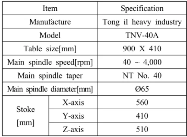
Table 1 Specifications of machining center
Item Specification
Manufacture Tong il heavy industry
Model TNV-40A
Table size[mm] 900 X 410 Main spindle speed[rpm] 40 ~ 4,000 Main spindle taper NT No. 40 Main spindle diameter[mm] Ø65
Stoke [mm]
X-axis 560
Y-axis 410
Z-axis 510
Table 2 Cutting conditions
Rough cutting
Finish cutting Spindle revolution[rpm] 2500 1800
Feed rate[mm/min] 200 220
Step over[mm] 1 0.5
Depth of cut [mm] 2 0.5
2.2 Experiment Tool and Material 2.2.1 Experiment Tool
The cutting tool used in this experiment was an uncoated general-purpose carbide end mill, which is used to machine free-form surfaces of metal molds.
2.2.2 Experiment Material and Shape
The specimen used in this experiment had a 70x70x19mm free-form surface shape. In the roughFig. 1 Dimensions of the workpiece
Cutting pattern modeling
Machined workpiece
Follow
periphery In the follow periphery method, machining is performed along the contour of modeling. A method where machining is conducted from the outside of the specimen to the inside was selected
Zig In the zig method, machining is performed as the tool proceeds. When it returns, the tool moves up to a safety height designated by a user, and goes through rapid feed. Then, it starts machining again. The cutting angle used was 45°, and the safety height for rapid feed was set to 10.
Zigzag In the zigzag method, machining is performed as the tool moves back and forth. In other words, it performs machining twice: once during proceeding and once during returning.
The cutting angle applied to the specimen was 45°.
Concentric zig
The concentric zig is a circular cutting pattern which gradually becomes larger or smaller from an optimal center point. This method applied the zig method, and machining is performed as the tool proceeds. When it returns, the tool moves up to a safety height machining, a flat end mill was used, and 0.5 mm was
left for finishing. In the finishing, it was machined as shown in Fig. 1, using a ball end mill.
2.3 Experiment Method
2.3.1Specimen Modeling and Tool Path Generation
Before the specimens were machined, 3D modeling was performed using the NX program, which is the CAD/CAM software of Siemens. In the program, the machining conditions were assigned, and tool paths were generated for each cutting pattern. Based on the simulation function of the program, the shapes after the machining were verified in advance, and it was checked if there was a problem. Finally, the NC codes of .the rough machining and the finishing were generated.
In the rough machining, all the specimens were identically machined in a ‘ㄷ’ form along the contour of the machining shape from the outside to the inside. In the finishing, the machining was conducted by generating tool paths using the seven cutting patterns based on down‐cutting, which has been verified in a number of surface roughness studies. Fig. 2 shows the tool paths and the shapes after the machining.
designated by a user, and goes through rapid feed. Then, it starts machining again. The safety height for rapid feed was set to 10, and a method where it gradually becomes smaller from an automatically calculated optimal center point was selected.
Concentric
zigzag The concentric zigzag method is similar to the concentric zig method, but it performs machining instead of the rapid feed. In other words, it performs machining twice: once during proceeding and once during returning.
Radial zig
The radial zig is a linear cutting pattern that extends from an optimal center point. This method applied the zig method, and machining is performed as the tool proceeds. When it returns, the tool moves up to a safety height designated by a user, and goes through rapid feed. Then, it starts machining again. The safety height for rapid feed was set to 10, and a method where machining is performed toward an automatically calculated optimal center point was selected.
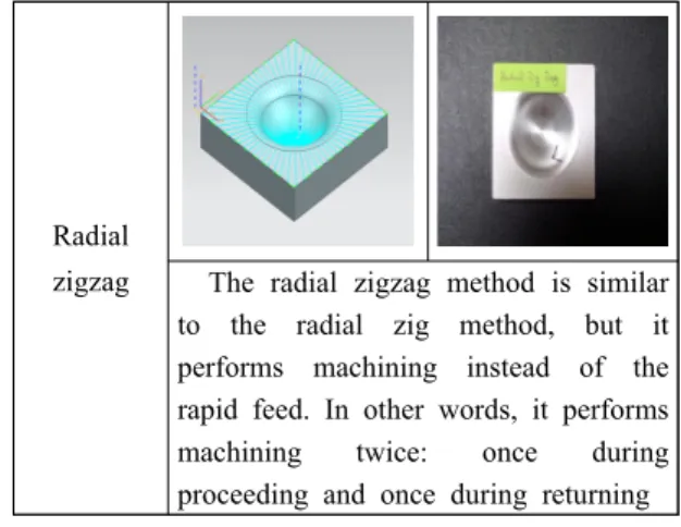
Radial
zigzag The radial zigzag method is similar to the radial zig method, but it performs machining instead of the rapid feed. In other words, it performs machining twice: once during proceeding and once during returning Fig. 2 Cutting pattern modeling and machined
workpiece
3. Experiment Results and Discussion
3.1 Surface Roughness and Shape Measurements
The surface roughness was measured at three random spots perpendicular direction of lay on the flat part of the specimen, among the two parts of the specimen (the flat part and the curved part), and an average value was obtained. Table 3 summarizes the measured surface roughness using the center line average roughness (Ra), the maximum height roughness (Rmax), and the 10‐point average roughness (Rz).
Table 3 Surface roughness results of different flat cutting patterns
Cutting pattern Surface roughness (µm)
Ra Rmax
Rz
Radial zig 1.32 9.30
8.01
Radial zigzag 1.52 11.00
9.06
Concentric zigzag 1.67 14.0310.44
Concentric zig 1.91 14.42
11.26
Zig 2.19 15.77
12.71
Zigzag 2.20 14.20
11.70
Follow periphery 2.26 16.33 12.90
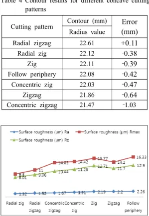
Table 4 Contour results for different concave cutting patterns
Cutting pattern Contour (mm)
Error (mm)
Radius valueRadial zigzag 22.61
+0.11
Radial zig 22.12
‐ 0.38
Zig 22.11
‐ 0.39
Follow periphery 22.08
‐ 0.42
Concentric zig 22.03‐0.47
Zigzag 21.86
‐0.64
Concentric zigzag 21.47 ‐1.03
Fig. 3 Surface roughness of the cutting pattern
Cutting
pattern
Analysis of the contour
Radial zigzag
Radius value
22.61 mm
Error +0.11 mm
Fig. 4 Measured contour characteristics of the cutting pattern
3.2 Discussion
In the case of the machining using a ball end mill, the tool path is determined using two criteria.
One is the increase in the machining efficiency,
and the other is the increase in the machining precision. This study considered the machining precision. The cutting patterns that had outstanding surface roughness were the radial zig and the radial zigzag. For the radial zig, Ra = 1.32 µm on the flat part; and for the radial zigzag, Ra = 1.52 µm.
Thus, their surface roughness values were superior to those of the other cutting patterns.
The cutting patterns that had an outstanding shape were the radial zigzag and the radial zig.
For the radial zigzag, the error was +0.11 mm in the curved part; and for the radial zig, ‐0.38 mm.
Thus, their shape values were superior to those of the other cutting patterns.
In this experiment, scour and chipping of the machined surface occurred due to the build‐up edge mentioned earlier. In particular, these phenomena were distinct in the zigzag cutting pattern where up‐cutting and down‐cutting were applied at the same time, rather than the zig cutting pattern where machining was conducted based on a one‐way method. In the future, a study on the relationship between build‐up edge and machining pattern needs to be performed.
The question of which cutting pattern is efficient needs to be answered based on the condition of the production requirements, considering the entire process. Studies on the development of a cutting pattern that can simultaneously satisfy the conflicting requirements of machining efficiency and machining precision are expected to be continuously performed.
4. Conclusion
In this study, an experiment was conducted to determine the optimal cutting pattern for the machining of aluminum alloy using a ball end mill, by machining the alloy through the generation of tool paths based on different cutting patterns and
by comparing the shapes and surface roughness values of the machined surfaces. The following conclusions are drawn.
1) The measurement of the flat‐part surface roughness for each cutting pattern indicated that the radial zig cutting pattern, which applied the zig pattern as a linear cutting pattern that extended from an optimal center point, showed the best machined surface, with a center line average roughness (Ra) of 1.32 µm.
2) The measurement of the curved part shape for each cutting pattern indicated that the radial zigzag cutting pattern, which applied the zigzag pattern as a linear cutting pattern that extended from an optimal center point, showed the best shape, with a concave part shape error of +0.11 mm.
References
1. E. K. Henriksen, 1975, “Chip Breaking-A study of Three Dimensional Chip Flow”, ASME, Vol.
9, pp 53~59.
2. K. Nakayama, 1972, “Chip Form Geometry and Chip Control”, JSPE, Vol. 38, No. 12, pp.
1070~1076.
3. Y. G. Kwon, 2000, “A study on the upward and downward cutting characteristics in the cutting of inclination plane using the ball end-mill”, Graduate School of Industry, Chungnam National University, M.S. Thesis, pp. 1-2.
4. C. Y. Jo, 2009, “Hemispheric Cutting-edge Optimization of a Ball End Mill for High-speed Machining”, Graduate School, Chonbuk National University, Ph.D. Thesis, pp. 11-13.
5. W. H. Lee, 2012, “A Study on the Ball End Mill Cutting Force for Inclined Surface Angles Using CAM/FEM”, Graduate School, Dong-A University, M.S. Thesis, pp. 8-10.
6. Y. J. Park, 1999, “Evaluation of the
Machinability of High-speed Ball End Milling on a Free-form Surface”, Journal of the Korean Society of Mechanical Engineers, pp. 66-70.
7. J. S. Kim, 2000, “Optimization of the Cutting Condition in the High-speed Machining of a Sculptured Surface Using a Ball End Mill”, Graduate School, Pusan National University, M.S. Thesis, pp. 21.
8. Rundaoz, 2011, “Study on Non-linear Regression Analysis of the Working Conditions of Aluminium Alloy Using End Milling”, Graduate School, Dong-A University, M.S.
Thesis, pp. 20-39.
9. J. G. Lee and J. D. Lee, 2008, “Precision Measurement Engineering, Kijeon Publishing”, pp. 327-353.
10. M. J. Park and K. Kim, 1998, “Effects of the tool path on the geometric characteristics of milled surface”, Journal of the Korean Society for Precision Engineering, Vol.15, No.6, pp.58-63.
11. K. Y. Lee, 2008, “Improvement of Cutting Performance of DLC Coated WC against Alloy”, Journal of the KSPSE, Vol. 12, No. 3, pp. 66-71.
12. J. S. Chung, J. U. Jun and M. K. Ha, 2002,
“Development of Cutting Tool in Non-ferrous Metals at Turning”, Journal of the KSPSE, Vol.
6, No. 1, pp. 82-87.