• 검색 결과가 없습니다.

Contact resistance characteristics of 2G HTS coils with metal insulation

N/A
N/A
Protected

Academic year: 2021

Share "Contact resistance characteristics of 2G HTS coils with metal insulation"

Copied!
5
0
0

로드 중.... (전체 텍스트 보기)

전체 글

(1)

Vol.20, No.4, (2018), pp.26~30 https://doi.org/10.9714/psac.2018.20.4.026

```

1. INTRODUCTION

Today, it is well known that NI superconducting coils have self-protection capabilities not found in conventional superconducting coils. When a quench occurs in the NI coil, the current flowing is bypassed to the adjacent turn [2]. In this case quench detection and protection system are not required. However, an NI coil has a long charge delay time.

In DC applications such as NMR and laboratory high field magnets, slow charge and discharge rates are not an issue.

However, for large HTS field coils of rotating machines such as superconducting generators and motors, relatively fast charge and discharge ramp rates and mechanical strength are required. In this case, the MI technique was used to co-wind a metallic tape such as SS tape from the viewpoint of the stiffener [3, 4]. The magnitude of the Joule heat generated by the bypass current when quench occurs is related to the stability of the coil. The larger the Joule heat, the lower the stability. Charge delay can be mitigated by increasing contact resistance (R ct ) and high R ct reduces coil stability. It is therefore important to design a coil with R ct that minimizes charge delay and ramping losses while maintaining reliable self-protection. In order to reduce the long charge delay time, NI method using SS–cladding 2G HTS tape method [5], MI method co-winding using 2G HTS tape and metal tape [3], and MI method installed with parallel resistor such as indium sheet on the side of pancake-type MI coil [1] were tried. Also, a study on the effect of cyclic loading and surface coatings has been reported to develop a technique for controlling contact

resistance between two REBCO tapes [6].

In this study, metal insulation model coils using Al, brass and one-sided Cu-plated SS tape were fabricated and evaluated. These results were compared with those of metal insulation coils using SS tape and Cu-plated SS tape. The contact resistance between turn-to-turn, the sudden discharge and the current charging delay time for model coils were discussed.

2. EXPERIMENT 2.1. Preparation of Metal Tapes

Total five metal tapes were prepared with a metal tape for co-winding as shown in Fig. 1. An Al tape and a brass tape are general products made by rolling. The electro-polished SS 310S is used as a substrate material.

Cu-plated SS tape is copper-plated around the electro-polished SS 310S tape and described in detail in reference [7]. One side of the wide SS 316L tape was electroplated with Cu and then cut to a width of 4 mm so that the edges were free of the copper. The specifications of these metal tapes and 2G HTS tapes are summarized in Table 1.

2.2. Fabrication of Model Coils

2G HTS tapes was manufactured by SuNAM and electroplated with Cu as a stabilizer. The width was approximately 4.0 mm, and the thicknesses were 0.138, 0.139, 0.15 and 0.115 mm. A no insulation model coil and five metal insulation model coils were fabricated.

Anodized aluminum bobbins with inner diameter 80 mm were used. The coil manufacturing method is described in

Contact resistance characteristics of 2G HTS coils with metal insulation

M. H. Sohn * , H. Ha, and S. K. Kim

Superconductivity Research Center, Korea Electrotechnology Research Institute, Changwon, Korea

(Received 5 December 2018; revised or reviewed 27 December 2018; accepted 28 December 2018)

Abstract

The turn-to-turn contact resistance of 2G high temperature superconducting (HTS) coils with metal insulation (MI) is closely related to the stability of the coils, current charging rate and delay time [1]. MI coils were fabricated using five kinds of metal tapes such as aluminum (Al) tape, brass tape, stainless steel (SS) tape, copper (Cu)-plated tape and one-sided Cu-plated SS tape. The turn-to-turn contact surface resistances of co-winding model coils using Al tape, brass tape, and SS tape were 342.6, 343.6 and 724.8 ·cm 2 , respectively. The turn-to-turn contact resistance of the model coil using the one-sided Cu-plated SS tape was 248.8

·cm 2 , which was lower than that of Al and brass tape. Al or brass tape can be used to reduce contact resistance and improve the stability of the coil. Considering strength, SS tape is recommended. For strength and low contact resistance, SS tape with copper plating on one side can be used.

Keywords: contact resistance, metal insulation, no insulation, 2G HTS coil

* Corresponding author: [email protected]

(2)

TABLE I

S PECIFICATIONS OF FIVE TYPES OF METAL TAPES

Type Thickness [mm] Width [mm]

Al tape 0.1 4.16

Brass tape 0.15 4.37

SS tape (310S) 0.106 4.00

Cu-plated SS tape (310S) 0.144 4.10

One-sided Cu-plated SS tape (316S)

0.112 4.23

Fig. 1. Schematic diagram of four types of HTS coils. (a) no insulation, (b) metal insulation coil, and (c) metal tapes for insulation.

Fig. 2. Photo of model coils. (a) NI coil (NI50), (b) Al tape insulation coil (MI50-Al), (c) Brass tape insulation coil (MI50-Brass), (d) SS tape insulation coil (MI50-SS), (e) Cu-plated SS tape insulation coil (MI50-SS(2Cu)), and (f) one-sided Cu-plated SS tape insulation (MI50-SS(1Cu).3.

detail in Reference [7]. Model coils were co-wound 50 turns with a winding tension of 2.0 ~ 3.0 kgf of metal tapes and 2.0 kgf of 2G HTS tape. Fig. 2 shows an NI model coil and five MI model coils.

2.3. Test Setup

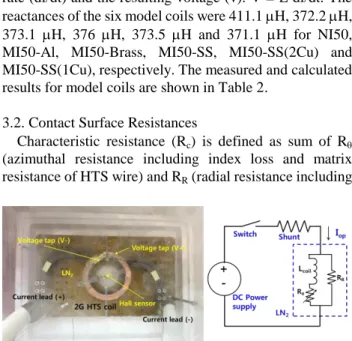
The model coils were characterized as in the previous study [7]. Each model coil for characterization was prepared as shown in Fig. 3 (a). A Hall sensor was placed at the center of the model coil to measure the intensity of the central magnetic field. A 2G HTS model coil, a DC power supply, a shunt resistor, and a switch are shown in Fig. 3 (b).

I-V characteristics of each coil, sudden discharge experiments, and charging tests according to various ramp rates were conducted. All tests were performed in liquid nitrogen.

3. RESULTS AND DISCUSSIONS 3.1. I-V Test

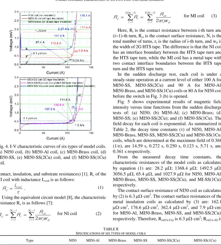
I-V characteristic curve of each model coil is shown in Fig. 4. The I c ’s of the NI coil (NI50 coil), the Al tape insulation coil (MI50-Al coil), the brass tape insulation coil (MI50-Brass coil), the SS tape insulation coil (MI50-SS coil), Cu-plated SS tape insulation coil (MI50-SS(2Cu) coil) and the one-sided Cu-plated SS tape insulation coil (MI50-SS(1Cu) coil) were 97.4A, 110.4 A, 107.8 A, 114.6 A, 108.8 A, and 107.0 A respectively. The voltage is generated by the inductance component according to the speed when the current is applied. The voltage is 37 mV, 399 mV, 847 mV, 391 mV, 381 mV, and 400 mV, respectively. For the NI50 coil, the ramp rate was set to 0.09 A/s because the turn-to-turn contact resistance was very small and current sharing occurred. For the MI50-Brass coil, the ramp rate was set to 2.27 A/s. For the other MI coils, the current ramp rate was set to about 1 A/s.

The indexes (n values) of these five model coils were calculated. The results are summarized in Table 2. The higher the n-value in the I-V characteristic curve, the more rapidly the voltage increases as the current increases. The n-value of MI50-SS was the greatest value of 58.1 and the smallest n-value of MI50-SS (2Cu) using copper-plated SS was 13.5. The n-values of MI50-Al and MI50-Brass were 37.7 and 39.1, respectively. Because the measured voltage per unit length in the flux flow region was less than 0.2

V/cm, the n value of NI50 coil could not be calculated but it was considered to be very small. This n-value is closely related to the turn-to-turn contact resistance of the model coil to be calculated in the next section. As the turn-to-turn contact resistance decreases, the generated bypass current becomes larger and the value of n decreases.

The reactance (L) can be obtained from the current ramp rate (di/dt) and the resulting voltage (v). V = L di/dt. The reactances of the six model coils were 411.1 H, 372.2 H, 373.1 H, 376 H, 373.5 H and 371.1 H for NI50, MI50-Al, MI50-Brass, MI50-SS, MI50-SS(2Cu) and MI50-SS(1Cu), respectively. The measured and calculated results for model coils are shown in Table 2.

3.2. Contact Surface Resistances

Characteristic resistance (R c ) is defined as sum of R 

(azimuthal resistance including index loss and matrix resistance of HTS wire) and R R (radial resistance including

(a) (b)

Fig. 3. Photo of model coils and measurement array (a), and

schematic drawing of the test circuit (b).

(3)

Fig. 4. I-V characteristic curves of six types of model coils.

(a) NI50 coil, (b) MI50-Al coil, (c) MI50-Brass coil, (d) MI50-SS, (e) MI50-SS(2Cu) coil, and (f) MI50-SS(1Cu) coil.

contact, insulation, and substrate resistances) [1]. R c of the NI coil with inductance L coil is as follows:

 .

coil c

R  L (1)

Using the equivalent circuit model [8], the characteristic resistance R c is as follows [7]:

1

1 1

1 2

t

t

N

i i d

ct N

i i

c r w

R R

R  for NI coil (2)

2 ( 1 )

1 )

1 ( 2

1 2

t

t

N

i i d

ct N

i i

c r w

R R

R  for MI coil (3)

Here, R i is the contact resistance between i-th turn and (i+1)-th turn, R ct is the contact surface resistance, N t is the total number of turns, r i is the radius of i-th turn, and w d is the width of 2G HTS tape. The difference is that the NI coil has an interface boundary between the HTS tape turn and the HTS tape turn, while the MI coil has a metal tape with two contact interface boundaries between the HTS tape turn and the HTS tape turn.

In the sudden discharge test, each coil is under a steady-state operation at a current level of either 100 A for MI50-SS, MI50-SS(2Cu) and 90 A for MI50-Al, MI50-Brass, and MI50-SS(1Cu) coils or 80 A for NI50 coil before the switch in Fig. 3 (b) is opened.

Fig. 5 shows experimental results of magnetic field intensity versus time functions from the sudden discharge tests of: (a) NI50; (b) MI50-Al; (c) MI50-Brass; (d) MI50-SS; (e) MI50-SS(2Cu); and (f) MI50-SS(1Cu). The field decay for each coil is exponential. As summarized in Table 2, the decay time constants () of NI50, MI50-Al, MI50-Brass, MI50-SS, MI50-SS(2Cu) and MI50-SS(1Cu) coils, which are determined at the maximum field of 0.368 (1/e), are 14.59 s, 0.272 s, 0.250 s, 0.123 s, 5.71 s, and 0.361 s respectively.

From the measured decay time constants, the characteristic resistances of the model coils as calculated by equation (1) are: 28.2 ; 1368.4 ; 1492.5 ;

3056.5 , 65.4 , and 1027.9  for NI50, MI50-Al, MI50-Brass, MI50-SS, MI50-SS(2Cu), and MI-SS(1Cu), respectively.

The contact surface resistance of NI50 coil as calculated by (2) is 6.3 ·cm 2 . The contact surface resistances of the metal insulation coils as calculated by (3) are: 162.1

·cm 2 , 176.6 ·cm 2 , 362.4 ·cm 2 , and 7.9 ·cm 2 for MI50-Al, MI50-Brass, MI50-SS, and MI50-SS(2Cu), respectively. Therefore, R ct(Cu-Cu) is 6.3 ·cm 2 ; R ct(Cu-Al) is TABLE II

S PECIFICATIONS OF SIX TYPES OF MODEL COILS

Type NI50 MI50-Al MI50-Brass MI50-SS MI50-SS(2Cu) MI50-SS(1Cu)

2G HTS tape SuNAM SuNAM SuNAM SuNAM SuNAM SuNAM

Average critical current [A]* 228 238 217 238 228 256

Metal tape - Al brass SS 310S Cu-plated SS 310S one-sided Cu-plated

SS 316L

I.D./O.D. [mm] 80/93.8 80/105.2 80/106.5 80/104.3 80/108.2 80/106.2

Length [m] 13.6 14.4 14.6 14.5 14.8 14.6

No. of turns 50 50 50 50 50 50

Index (n-value) - 37.7 39.1 58.1 13.5 22.8

Inductance [μH] 411.1 372.2 373.1 376.0 373.5 371.1

Characteristic resistance [μΩ] 28.2 1368.4 1492.5 3056.6 65.4 1027.9

Decay time constant () [s] 14.59 0.273 0.250 0.123 5.71 0.361

Critical current [A]** 97.4 110.4 107.8 114.7 109.0 107.0

Contact surface resistance [μΩcm 2 ] 6.3 171.3 171.8 362.4 7.9 -

Turn-to-turn contact surface resistance [μΩcm 2 ]

6.3 342.6 343.6 724.8 15.8 245.8

* 1 mV/cm ** 0.1 mV/cm criteria

(4)

Fig. 5. Variation of normalized magnetic field intensity in six model coils. (b) is an enlargement of (a)

162.1 ·cm 2 , R ct(Cu-Brass) is 176.6 ·cm 2 , R ct(Cu-SS) is 362.4 ·cm 2 , and R ct(Cu-SS(2Cu)) is 7.9 ·cm 2 . The contact surface resistance between turn-to-turn is R ttt =R ct for NI coil, but R ttt =2R ct for MI coil. Therefore, the contact surface resistance between turn-to-turn is 6.3 ·cm 2 ; 342.6 ·cm 2 ; 343.6 ·cm 2 ; 724.8 ·cm 2 , and 15.8

·cm 2 for NI50, MI50-Al, MI50-Brass, MI50-SS, and MI50-SS(2Cu), respectively.

Assuming that both of the contact surface resistances of the one-sided Cu-plated SS tape in MI50-SS (1Cu) coil are the same, it is 122.9 ·cm 2 using equation (3). Therefore, the average contact surface resistance between turn-to-turn of MI50-SS (1Cu) is .245.8 ·cm 2 . Therefore, the order of magnitude of resistance between turn-to-turn becomes smaller in the order of SS tape, brass tape, Al tape and one-sided Cu-plated SS tape.

The difference in contact resistance results for each researcher seems to be due to the different tension conditions of the coils and the different surface roughness of the 2G HTS tapes and the metal tapes used. Lu reported that the contact resistance can be controlled by oxidizing the surface of the 2G HTS tape or the surface of the metal tape [9].

3.3. Charging Tests

In order to observe the charging delay of the model coils, the magnetic field charging characteristics with current ramp rate were investigated. In Fig. 6, the target current value is chosen so that current sharing rarely occurs during charging. The target currents of the MI50-SS and

MI50-SS(1Cu) coils were set at 90 A. The target currents of the MI50-SS and MI50- SS(2Cu) coils were set at 100 A, and that of the NI 50 coil was set at 80 A. The results of NI50, MI50-SS and MI50-SS(2Cu) were reported already in reference [7]. The actual charging time is the sum of the ramping time and the waiting time (or delay time). For the NI 50, when the slow ramp rate was 0.096 A/s, the delay time was 13.3 s and the charging time was about 845.3 (=

832+13.3) s. In the case of the MI50-SS coil, the delay time was less than 1 s, even at 38 A/s. The delay time of MI50-SS (2Cu) coil with ramp rate of 2.25 A/s was 18.6 s.

When the ramp rate was 26.3 A/s, it was extended to 44.4 s.

In this study, the results of the magnetic field intensity-time curves of the MI50-Al, MI50-Brass and MI50-SS(1Cu) coils with respect to current ramping rates are shown in Fig. 6. For the MI50-Al when the relatively fast ramp rate was 31.3 A/s, the delay time was 1.1 s and the charging time was about 4 (= 2.9+1.1) s. In the case of ramp rate 6.0 A/s, delay time was 0.8 s. The result of the MI50-Brass was the same as that of the MI50-Al. In the MI50-SS(1Cu) coil, the delay time was 1.5 s at the current

Fig. 6. Magnetic field intensity-time curves of three models

with respect to current ramping rate. (a) MI50-Al coil, (b)

MI50-Brass coil, and (c) MI50-SS(1Cu) coil.

(5)

Fig. 7. Delay time according to the current ramp rate in six model coils. (b) is an enlargement of (a)

ramp rate of 37.4 A/s and about 1.1 s at 6.1 A/s. These values are brief compared to NI50 and MI50-SS(2Cu) coils.

The delay time according to the current ramp rate in six model coils are shown in Fig. 7. The larger the turn-turn contact resistance of the coil, the shorter the delay time.

Therefore, metal insulation coils using Al, Brass, and one-sided Cu-plated SS tape as insulation material have a time delay within a few seconds even when a fast ramp rate of the current was about 30 A/s. To increase the stability of the coil, we can use Al or brass tape. And particularly, in consideration of the strength and contact resistance of the metal tape for co-winding coils, the one-sided Cu-plated SS tape is recommended.

4. CONCLUSIONS

Six types of model coils—an NI coil, five MI coils co-wound with various metal tapes—were prepared in order to evaluate turn-turn contact resistance, decay time constant, charging characteristics for achieving high safety of 2G HTS coils during quenching. The contact surface resistances between turn-to-turn of MI50-Al coil, MI50-Brass coil and MI50-SS(1Cu) are 342.6 ·cm 2 ; 343.6 ·cm 2 ; 245.8 ·cm 2 , respectively. From the results, reduction of turn-to-turn contact surface resistance in model coils was achieved by using MI coil co-wound with one-sided Cu-plated SS tape.

When manufacturing metal insulation coils, Al, brass, and SS tape can be used as insulation material. Al and brass can be used to reduce the contact resistance and improve the stability of the coil. Considering the strength of the metal tape for co-winding, SS tape is recommended. For the strength and low contact resistance, one-sided Cu-plated SS tape can be used. In this case, the delay time is longer, but it is about 1 to 2 seconds. In order to design a stable MI coil, the minimum thickness and strength of the metal insulation tape should also be considered.

ACKNOWLEDGMENT

This research was supported by Korea Electrotechnology Research Institute (KERI) Primary Research Program through the National Research Council of Science & Technology (NST) funded by the Ministry of Science and ICT (MSIT) (No. 18-12-N0101-90).

REFERENCES

[1] M.-H. Sohn et al., “Stability of 2G HTS double pancake coil with metal insulation and two parallel resistors,” IEEE Trans. Appl.

Supercond., vol. 27, no. 4, Jun. 2017, Art. no. 4602504.

[2] S. Hahn, D. K. Park, J. Bascunan, and Y. Iwasa, “HTS pancake coils without turn-to-turn insulation,” IEEE Trans. Appl.

Supercond., vol. 21, no. 3, pp. 1592–1595, Jun. 2011.

[3] M.-H. Sohn et al., “Stability and quench behaviors of conduction-cooled 2G HTS coil co-wound with SS tape,” IEEE Trans. Appl. Supercond., vol. 26, no. 4, Jun. 2016, Art. no.

4701304.

[4] J. Choi et al., “Characteristic analysis of a sample HTS magnet for design of a 300 kW HTS DC induction furnace,” IEEE Trans. Appl.

Supercond., vol. 26, no.3, April 2016, Art. no.3700405.

[5] G. Kim et al., “Quench behavior of a no-insulation coil wound with stainless steel cladding REBCO tape at 4.2 K,” Supercond. Sci.

Technol., vol. 30, (2017) Art. no. 075001.

[6] J. Lu et al., “Contact resistance between two REBCO tapes: the effects of cyclic loading and surface coating,” Supercond. Sci.

Technol., vol. 31 (2018), Art. no. 085006.

[7] M.-H. Sohn et al., “Controllability of the Contact Resistance of 2G HTS Coil With Metal Insulation,” IEEE Trans. Appl. Supercond., vol. 28, no. 3, Apr. 2018, Art. no. 4602705.

[8] X. Wang et al., “Turn-to-turn contact characteristics for equivalent circuit model of no-insulation ReBCO pancake coil,” Supercond.

Sci. Technol., vol. 26, no. 3, Jan. 2013, Art. no. 035012.

[9] Jun Lu et al., “Turn-to-turn contact resistance of surface oxidized REBCO in pancake coils,” presented at ASC 2018.

수치

Fig. 1. Schematic diagram of four types of HTS coils. (a) no  insulation, (b) metal insulation coil, and (c) metal tapes for  insulation
Fig. 4. I-V characteristic curves of six types of model coils.
Fig. 6. Magnetic field intensity-time curves of three models  with respect to current ramping rate
Fig. 7. Delay time according to the current ramp rate in six  model coils. (b) is an enlargement of (a)

참조

관련 문서