이중대역 오프셋 카세그레인 반사판 안테나용 메타재질구조 모사 주파수 선택표면 부반사판 설계
김현수*, 강승택*, M.K.Khattak*, 전진수*, 박정훈*
Design of Metamaterial-Inspired FSS Sub-Reflector for a Dual-Band Offset Cassegrain Reflector Antenna
Hyeonsu Kim*, Sungtek Kahng*, M. Kamran Khattak*, Jinsu Jeon*, and Jeong-hoon Park*
요 약
본 논문에서는, 오프셋 카세그레인 반사판 안테나가 물리적 크기의 증가없이 Ku와 Ka 이중대역 신호를 다룰 수 있는 구조로 설계된 다. 계산시간 및 구현비용을 고려하여, 주반사판 대신에 부반사판에 Ka대역 신호는 반사시키고 Ku대역은 통과시키는 주파수 선택성 을 부여한다. 쌍곡선 부반사판 표면의 주파수 선택표면은 8각형 금속 링을 위 아래로 둔 다층매질의 단위 쎌의 주기적 형태로 구성된 다. 정밀한 전자기 모의시험을 통해 제안한 구조가 19 GHz와 45 GHz에서 동작함을 확인한다.
Key Words : Dual-band, Offset Cassegrain reflector antenna, Frequency selective surface, Satellite
ABSTRACT
In this paper, a design of an offset Cassegrain antenna is proposed for Ku and Ka dual-band without increasing the antenna size. For Efficiency of computation and implementation, the frequency selectivity surface (FSS) of reflecting the Ka-band signal and passing the Ku-band is provided for the sub-reflector instead of the main reflector. The proposed FSS hyperboloid sub-reflector is the periodic structure of a unit cell comprising octagon metal rings embedded in the multiple layers. The proposed design is verified for 19 GHz and 45 GHz bands by the use of precise electromagneitc-field simulations.
※ 본 연구는 인천대학교의 자체 연구비 과제 지원으로 수행되었음.
*인천대학교 정보통신공학과 ([email protected])
접수일자 : 2015년 4월 29일, 수정완료일자 : 2015년 5월 6일, 최종게재확정일자 : 2015년 5월 15일
I. INTRODUCTION
In satellite communication as well as military and aerospace vehicles, high directivity antennas are highly preferred. Nine out of ten cases, a reflector antenna with a feed horn is commonly used for the long distance communication, since it has a relatively large radiation aperture almost equivalent to a large-sized array antenna or greater[1].
Most reflector antennas have feed horns at the foci in the line of the reflection path from the reflecting surfaces and this causes the degradation in the radiation characteristics due to the blockaga error. Therefore, the dual-reflector geometry is proposed to move the feed horn out of the line between the center of the main reflector and
the horn which is called the offset reflector antenna[2].
A good example of the aforementioned antenna is the offset Cassegrain structure as shown in [2, 3] or Fig. 1 in this paper. Different from the typical single reflector antenna, the feed horn does not face the main reflector, but the sub-reflector faces both the feed and the main reflecting surface. In the Cassegrain configuration, a hyperboloid shaped metallic sub-reflector reflects the wave from the feed horn to the main reflector that re-reflects the incoming signal in the form of a plane wave to the target. While the main reflector is not so complete a paraboloid as that of the single reflector version that constrains the maximum radiation aperture, it can avoid the blockage error. This is an advantage, but a question may arise what other benefits the dual-reflector
antenna will bring.
If we turn our attention to a multi-function property to be gained by the Cassegrain antenna, it is possible to achieve multiple bands. As for the single reflector antenna, only one feed can be placed at the focal point, and the number of frequency bands totally relies on that of the primary source. However, the offset dual reflector structure has two focal points as an imaginary one and its image with reference to the sub-reflector, and if the sub-reflector is an FSS to have one feed horn for f1 and another for f2 respectively, before and behind the sub-reflector. C. Tienda et al changed the sub-reflector by a flat phase compensating non-uniform array surface in [4]. Also, Cheong et al presented a planar periodic FSS substituting for the sub-reflector in [5].
In this paper, a new FSS sub-reflector is introduced to iron out the drawbacks of the flat geometries in references 4 and 5, which the phase discontinuities between the adjacent discrete cells and errors in the phase compensation.. Keeping the hyperboloid shape, the unit cell of styrofoam- inserted nine layers with two octagon metal rings is replicated and its periodic configuration replaces the sub-reflector. This is designed to pass 19-GHz Ku-band and reflect 45-GHz Ka-band signal and have two feed horns in one antenna structure. A precise electromagnetic simulator is adopted to verify the proposed design..
Ⅱ. DESIGN OF THE FEED HORN
Prior to the discussion on the complete realization of the offset Cassegrain antenna as shown in Fig. 1, the feed horn is designed in this section.
(a) A sketch of the standard scheme
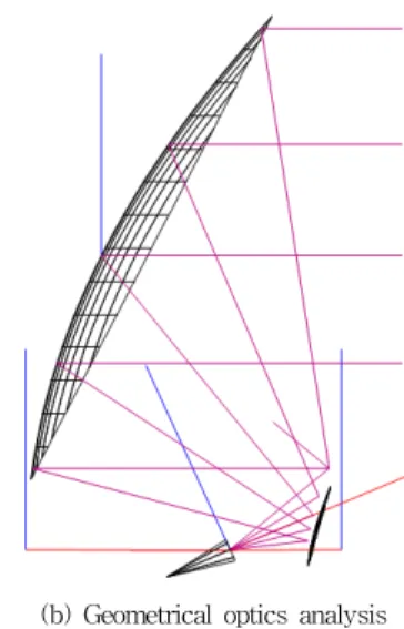
(b) Geometrical optics analysis
Figure 1. Offset Cassegrain reflector antenna
The geometrical information on the entire structure is decided as 60.96 cm, 38.1 cm, 7.62 cm, 12.73 cm, 72.56°, and 35.8° as the main reflector aperture, focal length, offset, sub-reflector diameter, main reflector subtended angle, and sub-reflector subtended angle, respectively.
The sub-reflector has the eccentricity of 2.5 as a hyperbola. Along with this, the Ka-band feed horn is designed so that its signal is reflected from the sub-reflector and impinges to the main reflector from 43.5 GHz to 45.5 GHz.
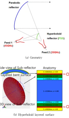
(a) Geometry
(b) E- and H-plane far-field patterns
(c) Test set-up for EM field observation at two reference planes
(d) EM field observation at plane 1 at the feed horn
(e) EM field observation at plane 2 near the sub-reflecto Figure 2. Feed horn design and electromagnetic
performance at 45 GHz
Fig. 2 shows the geometry and electromagnetic properties of the feed horn investigated in terms of 45 GHz and 0.67 cm as
(wavelength.. .Fig. 2(a) as the 3-segmented circular horn makes the radiation patterns almost equal over the E- and H-planes with the gain of25 dBi as in Fig. 2(b). When the feed at plane 1 illuminates plane 2 of the hyperboloid as Fig. 2(c) with Ey and Hx as presented in Fig.'s 2(d) and 2(e), the beam-distribution is very good and uniform for every point of the sub-reflector surface.
Ⅲ. DESIGN OF THE DUAL-BAND FSS HYPERBOLOID
The dual-band signals will be given by the two feed horns like the following.
(a) Geometry
(b) Hyperboloid layered surface
(c) Unit cell of (b)
Figure 3. FSS hyperboloid for 2 feed horns
Fig. 3(a) is the final complete structure where two feed horns share the main reflector for dual-band communication. To do so, the hyperboloid shouldn't be a solid metal surface any longer, but should be a layered media comprising dielectrics and periodic metal rings in the horizontal direction as in Fig. 3(b). The 3D view of the unit cell is portrayed like Fig. 3(c). The unit cell is repeated to form a periodic structure as the hyperboloid.
(a) Front-view the geometry
(b) Periodic surface
(c) Octagon metal rings for the unit cell
Figure 4. FSS hyperboloid for 2 feed horns and the critical component of the unit cell
The 3D view of Fig. 3 comes as Fig.'s 4(a) and 4(b) as the front view of the sub-reflector. The PEC rings of the Fig. 3(b) are magnified to Fig. 4(c) as the octagon shape
put in the area 0.24 cm
×
0.24 cm with eight sides of 0.074-cm length and 0.023-cm width.. As is done for Fig.2, GEMS◯R as a commercial EM simulator is adopted to conduct precise numerical experiments on the performances of the proposed sub-reflector.
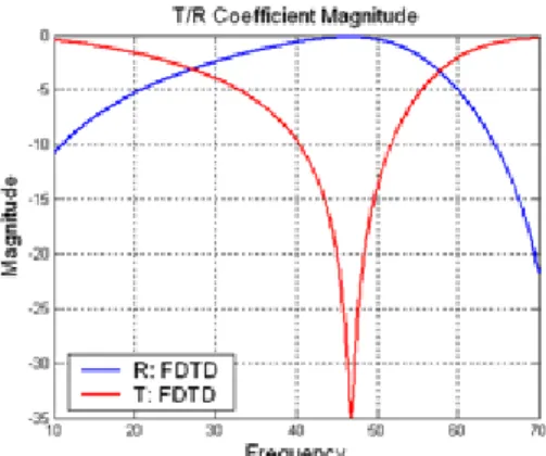
(a) Illumination and scattering
(b) Ku-band passed and Ka-band reflected
(c) Effective refractive index of the FSS hyperboloid
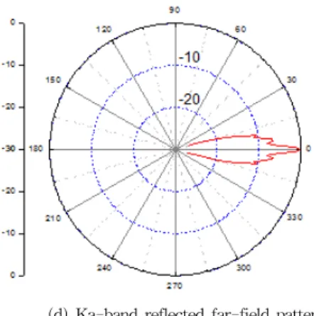
(d) Ka-band reflected far-field pattern
Figure 5. Reflection test set-up, FSS and metamaterial observation, and reflected radiated filed pattern
Fig. 5(a) is the test vehicle for the scattering of the Ka-band signal illumination on the sub-reflector. It is a matter of course that the Ku-band feed is placed behind the sub-reflector without any problem. Both the Ku- and Ka-band signals hit the FSS hyperboloid as the normal incidence and we have the transmission and reflection results as we want as in Fig. 5(b). 19 GHz as the Ku-band is transmitted and 45 GHz as the Ka-band signal is reflected by the designed dual frequency FSS. Besides, fortunately, no interference problem due to harmonics is found in the result. Furthermore, this is consistent with a positive real refractive index for the Ku-band transmission and a pronounced imaginary behavior for the Ka-band reflection in the observation of Fig. 5(c) as similar to the metamaterial approach. Lastly, the strength of the scattered field of the Ka-band signal is checked.
Fig. 5(d) shows the resultant directivity of the reflected far-field is 30 dB which improves the 25 dBi gain of the feed horn and can work as an appropriate secondary in the offset dual reflector antenna system.
V. CONCLUSIONS
This paper proposed a dual-band sub-reflector for dual-band offset Cassegrain reflector antenna. Instead of the flat version of the sub-reflector causing the phase error in the secondary source, the multi-layered curved FSS was designed to pass the target Ku-band and reflect the Ka-band signal. The feed horn and the secondary source have high antenna directivity that can guarantee the high antenna gain for satellite communication as a lighter airborne structure.
REFERENCES
[1] John D. Kraus, and Ronald J. Marhefka, 'Antennas for all Application,'McGraw-Hill 2002
[2] W. V. T. Rush, A. Prata, Y. Rahmat-Samii, and R.A. Shore,
"Derivation and application of the equivalent paraboloid for classical offset Cassegrain and Gregorian antennas", Trans.
Antennas and Propagat., Vol.38, pp. 1141-1149, Aug. 1990.
[3] K. W. Brown, A. Prata Jr., "A design procedure for classical offset dual reflector antennas with circular apertures", IEEE Trans. Antennas Propagat., Vol. 42, no. 8, pp. 1145-1153, Aug. 1994..
[4] C. Tienda, M. Arrebola, and J. A. Encinar, "Recent Developments of Reflectarray Antennas in Dual-Reflector Configurations,"International Journal of Antennas and Propagation, Volume 2012, Article ID 125287, pp.1-10, 2012..
[5] C.-H. Cheong, H.-M. Jeong, K.-W. Kim, K.-H. Bae, H.-S.
Tae and E. Gennadiy, "Multi-band directional antenna for satellite communications," Korean Society of Aero-Space Journal, Vol.38, No.12, pp. 1223-1231, 2010.
저자
김 현 수(Hyeonsu Kim) 비회원
․2014년 2월:인천대학교 정보통신공 학과(공학사)
․2014년 3월 ~ 현재:인천대학교 정보 통신공학과 석사과정
<관심분야> : 단말기 NFC 안테나 설계, 초고주파 부품 및 안 테나 설계, 메타재질구조 이론 및 응용
강 승 택 (Sungtek Kahng) 정회원
․2000년 2월:한양대학교 전자통신 공 학박사
․2000년 4월:한양대학교 산업과학연구
소 연구원
․2004년 2월:한국전자통신연구원 통신 위성개발센터 선임연구원
․2004년 ~ 현재:인천대학교 정보통신 공학과 교수
․2007년 ~ 현재:송도 국방벤처 자문교수
․2007년 ~ 현재:한국통신학회 마이크로파 및 전파 연구회 간사, 위원장, 한국전자파학회 편집위원, 국제이사
․2014년 12월 대한전기학회 학술상 수상(광파 및 전자파 분 야)
<관심분야> : 전자파 수치 해석 및 응용, EMI/EMC 대책, 초고주파 부품 및 안테나 설계, 메타재질구조 이론 및 응용
Muhammad Kamran Khattak 비회원
․2012년 2월:스웨덴 Linneaus 대학 (공 학석사)
․2014년 3월 ~ 현재:인천대학교 정보 통신공학과 박사과정
<관심분야> : 전자파 수치 해석 및 응용, EMI/EMC 대책, 초고주파 부품, 안테나 광대역 흡수체, 설계, 메타재질구조 이론 및 응용
전 진 수(Jinsu Jeon) 비회원
․2013년 8월:인천대학교 정보통신공학 과(공학사)
․2013년 8월 ~ 현재:인천대학교 정보통 신공학과(공학석사과정)
<관심분야> : 착용형 안테나 설계, 무선전력전송(WPC) 코일 설계, 초고주파 부품 및 배열 안테나 설계, 메타재질구조 이 론 및 응용
박 정 훈(Jeong-hoon Park) 비회원
․1984년 2월:아주대학교 전자공학과 (공학사)
․1993년 2월:아주대학교 전자공학과 (공학석사)
․2005년 2월:아주대학교 전자공학과 (공학박사)
․2010년 3월 ~ 현재:인천대학교 정보통신공학과 교수 <관심분야> : 이동통신, 무선통신