1. 서 론
환경피로는 발전설비중 수분과 접촉하고 있는 기기들의 균열발생 메커니즘 중 하나이며 균열에 의한 기기 손상의 주요 원인중 하나인 것으로 알 려져 있다[1]. 따라서 발전소의 설계 및 운영 측
면에서 기기 재료의 수명을 예측 평가하고 관리,
하는데 있어 환경의 영향을 어떻게 고려하여야
할 것인지는 매우 중요하다 특히 원자력발전소.
의 안전등급 기기들은 비록 피로에 의한 손상 가 능성이 낮다는 것이 이미 알려져 있지만 원전의 수명 연장 또는 주기적 안전성 평가(PSR)와 같이
주요 기기들의 건전성을 평가 및 확인하는 과정 에서 중요하게 고려되고 있다[2]. 현재 가동중인
원전의 안전등급 기기들에 대한 피로설계는
비파괴 검사를 통해 발견 ASME B&PV Sec. III,
된 균열의 성장거동 평가는 ASME B&PV Sec.
을 따르고 있다 그러나 위에서 제시하고 있는
XI .
피로수명 곡선과 피로균열성장 곡선은 수화학 환 경의 영향이 충분히 고려되지 못하고 있으며 일 부 수화학 조건에서는 기존의 자료들이 충분히 보수적이지 못한 것으로 밝혀졌다[2-4]. 최근 이 와 관련하여 많은 연구들이 수행되었으며 특히 탄소강 및 저합금강에 대한 환경피로의 영향은
비교적 상세하게 연구되고 있다 스테인리스강에.
대해서는 많은 연구들이 진행중에 있으며 지금까 지 수행된 스테인리스강의 환경피로 실험결과들 은 주로 SS316NG와 SS304 등에 집중되어 있고 용존산소(dissolved oxygen, DO)량이 높은 조건에서 대부분 수행 BWR(boiling water reactor)
되어 용존산소나 용존수소 등의 수화학 조건이
환경을 모사한 저주기 피로실험장치 국산화 PWR
정일석†․김상재 이용성 송택호 홍승열․ ․ ․
Development of Low-Cycle Fatigue Test Rig in Simulated PWR Environments
I.S. Jeong, S.J. Kim, Y.S. Lee, T.H. Song and S.Y. Hong
Key Words: CF8M, Low-Cycle Fatigue(저주기 피로), PWR(Pressurized Water Reactor: 가압경수 로형 원자로), Strain-control(변형률 제어)
Abstract
For developing fatigue design curve of cast stainless steels that would be used in piping material of domestic nuclear power plants, a low-cycle fatigue test rig was built. It is capable of performing tests in pressurized high temperature water environment of PWR. Cylindrical specimens of CF8M were used for the strain-controlled environmental fatigue tests. Fatigue life was measured in terms of the number of cycles with the variation of strain amplitude at 0.04%/s strain rates. The disparity between target length and measured length of specimens was corrected by using finite element method. The corrected test results showed similar fatigue life trend with another previous results.
한전 전력연구원
†
E-mail : [email protected]
TEL : (042)865-5511 FAX : (042)865-5514
환경피로 특성을 명확히 판단하기가 어려운 실정 이다[4-6]. 따라서 본 연구에서는 국내 가압경수 로(PWR)의 가동환경을 모사할 수 있는 환경피로 실험 장비를 개발하고 원전 주냉각재 배관으로 사용되고 있는 주조 스테인리스강에 대한 실험을 수행하여 피로수명선도 작성을 위한 시범데이터 를 생산하였다.
저주기 환경피로실험장치 2.
2.1
1
. DO, pH, H2
. (strain control)
(fully reversed load) .
.
60kN, 1 ,
50mm, 350 ,
170bar .
.
2.2
1 .
.
(electric contact pressure gage, flow switch, safety valve)
(electric pressure sensor, thermo meter) . ,
3
.
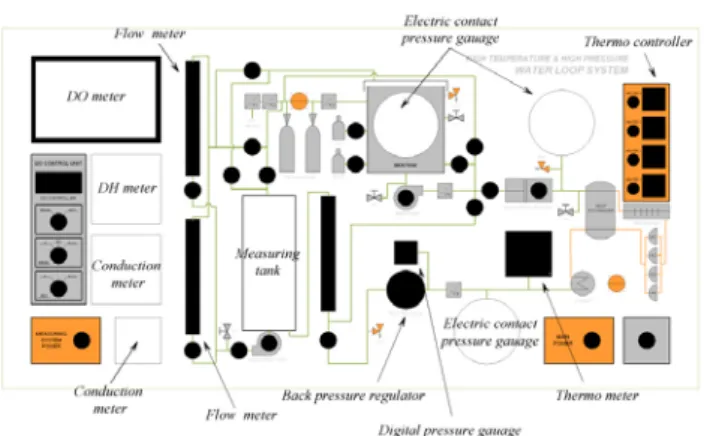
. 2
Fig. 1 The composition of loop
Fig. 2 The diagram of loop control panel
2.3
3
(autoclave)(1), (jig)
(lower structure)(2), (load cell)(31),
(32), (actuator)(33), (main frame)(3) .
.
PID .
(rod) (31)
.
(31)
,
(31) (32)
.
AUTO CLAVE
ACTUATOR
LOADCELL LOWER STRUCTURE
Fig. 3 Low-Cycle fatigue test rig in simulated PWR environments
.
. LVDT
autoclave .
. 2
. 2.4
Fig. 4 .
.
3.
5 .
Fig. 4 The load control program
Fig. 5 Photograph of low-cycle fatigue test rig
Fig. 6 Diagram of low-cycle fatigue test specimen
3.1
ASTM E 606-92[7]
6 .
19.05mm, 9.63mm ,
.
1 1
CF8MH(25wt% ferrite) .
3.2 PWR
autoclave 316 ,
15MPa, DO(dissolved oxygen) 5ppb
. R=-1
(strain rate) 0.04%/s (strain amplitude)
0.5%, 0.6%, 0.7%
.
1 . (strain
control) ,
25%
(N25) [8].
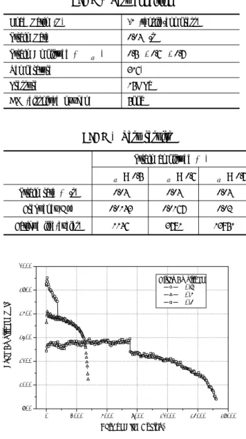
3.3
2 . 7
.
(strain hardening)
. 0.7, 0.6, 0.5%
. 0.5%
8000cycle .
,
.
.
.
Load Ratio (R) -1 (tensile/compress)
Strain Rate 0.04%/s
Strain Amplitude ( ε ) 0.5%, 0.6%, 0.7%
Temperature 316℃
Pressure 15MPa
DO (dissolved oxygen) 5ppb
Table 1 Test condition
Strain amplitude (%)
ε = 0.5 ε = 0.6 ε = 0.7
Strain rate (%/s) 0.04 0.04 0.04
Frequency(Hz) 0.0143 0.0167 0.02
Fatigue life(cycles) 1146 3781 13951
Table 2 Test results
0 3000 6000 9000 12000 15000 18000
800 1000 1200 1400 1600 1800 2000
Strain Amplitude 0.7%
0.6%
0.5%
Load Amplitude (kgf)
Fatigue Life (Cycles)
Fig. 7 Graph of load amplitude vs. fatigue life 3.4
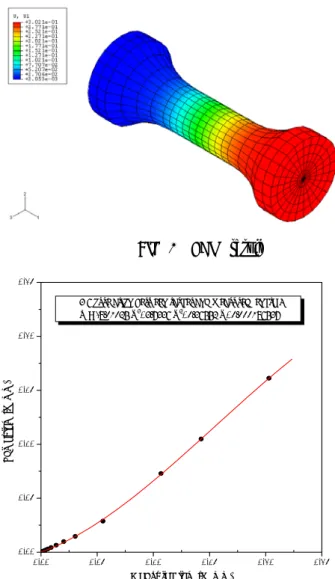
(
) .
8
(strain control) .
Fig. 8 Dimension of specimen
Fig. 9 FEM result
0.00 0.05 0.10 0.15 0.20 0.25
0.00 0.05 0.10 0.15 0.20 0.25
Target length (mm)
Measured length (mm)
< Correlation between target and measured length >
Y = -8.01025 X3+3.7336 X2+0.36552 X+0.000186537
Fig. 10 Relation of measure and target length
(mm)
FEM
(mm) Strain Amp.(εa)
0.1995 0.1581 0.0083
0.1320 0.0951 0.0050
0.1050 0.0705 0.0037
Table 3 The compensation results
(extensometer LVDT)
, PWR
(FEM, finite element method)
10 . x ,
y .
.
Strain amplitude . 3
.
3.5
strain amplitude PWR strain control ε-N
, ASME data 11
.
ASME design curve mean
curve .
11 ASME code
(low bound)
.
4.
12 CF8M
. CF8M 0.04%/s
.
. (strain hardening)
.
101 102 103 104 105 106
0.1 1.0 10.0
FEMbefore FEMafter
Strain Amplitude,εa(%)
Fatigue Life(Cycles) ASME Design Curve
Mean Curve RT Air
Fig. 11 The comparison of strain amplitude vs.
fatigue life
101 102 103 104 105 106
0.1 1.0 10.0
CF8M, unaged, 0.04, KEPRI CF8M, aged, 0.04, JAPAN CF8M, aged, 0.01, JAPAN CF8M, unaged, 0.04, JAPAN CF8M, unaged, 0.01, JAPAN 304SS, unaged, 0.01, JAPAN 316SS, unaged, 0.04, JAPAN 316SS, unaged, 0.01, JAPAN
Strain Amplitude,εa(%)
Fatigue Life(Cycles)
Fig. 12 The comparison of strain amplitude vs.
fatigue life included others results
5. 결 론
,
1 1
CF8M .
, .
,
.
후 기
( )
.
참고문헌
(1) Y.S. Garud, et.al., 1997, "Corrosion Fatigue of Water-Touched Pressure Retaining Components in Power Plants", EPRI TR-106696
(2) D.A. Gerber, 1998, "Evaluation of Environmental Fatigue Effects for a Westinghouse Nuclear Power Plant", 1998, EPRI TR-110043 (3) O.K. Chopra, 1999, "Overview of Fatigue Crack
Initiation in Carbon and Low-Alloy Steels in Light Water Reactor Environments", J. Pres. Ves. Tech.
Vol. 121.
(4) M. Itatani, et.al, "Fatigue Crack Growth Curve for Austenitic Stainless Steels in BWR Environment", 2001, J. Pres. Ves. Tech. Vol. 123.
(5) W. E. Ruther, et.al, 1993, "Environmentally Assisted Cracking in Light Water Reactors", NUREG/CR-4667, Vol.15
(6) O. K. Chopra, 1999, "Effects of LWR Coolant Environments on Fatigue Design Curves of Fatigues of Austenitic Stainless Steels", NUREG/CR-5704
(7) 1993, "Standard Practice for Strain-Controlled Fatigue Testing", ASTM E 606-92, pp. 523-537 (8) O. K. Chopra and W. J. Shack, 2003, "Review
of the Margins for ASME Code Fatigue Design Curve-Effects of Surface Roughness and Material Variability", NUREG/CR-ANL-02/39