*†김주곤: 대구경북과학기술원 웰니스융합연구센터 E-mail : [email protected], Tel : 053-785-4786 *소비 토마스 : 대구경북과학기술원 웰니스융합연구센터 *손병락 : 대구경북과학기술원 웰니스융합연구센터 *이동하 : 대구경북과학기술원 웰니스융합연구센터 **Alex Bates : 루이빌대학교, 기계공학과
**Sam Park : 루이빌대학교, 기계공학과
***정현열 : 영남대학교 정보통신공학과
*†Kim Joo-Gon : Wellness Convergence Research Center, DGIST.
E-mail : [email protected], Tel : 053-785-4786
*Sobi Thomas : Wellness Convergence Research Center, DGIST *Son Byung-Rak : Wellness Convergence Research Center, DGIST *Lee Dong-Ha : Wellness Convergence Research Center, DGIST **Alex Bates : Department of Mechanical Engineering, University
of Louisville
**Sam Park : Department of Mechanical Engineering, University of Louisville
***Chung Hyun-Youl : Department of ICE, Yeungnam University
600 W급 연료전지(PEMFC)의 설계 및 제작
Design and Development of 600 W Proton Exchange Membrane Fuel Cell
김주곤*†․정현열***․Alex Bates**․소비 토마스*․
손병락*․Sam Park**․이동하*
Kim Joo-Gon*†․Chung Hyun-Youl***․Alex Bates**․Sobi Thomas*․
Son Byung-rak*․ Sam Park**․Lee Dong-Ha*
(Submit date : 2014. 7. 2., Judgment date : 2014. 7. 2., Publication decide date : 2014. 8. 11.)
Abstract : The design of a fuel cell stack is important to achieve optimal output power. This study focuses on the evaluation of a fuel cell system for unmanned aerial vehicles (UAVs). Low temperature proton exchange membrane (LTPEM) fuel cells are the most promising energy source for robot applications because of their unique advantages such as high energy density, cold startup, and quick response during operation. In this paper, a 600 W open cathode LTPEM fuel cell was tested to evaluate the performance and to determine optimal operating conditions. The open cathode design reduces the overall size of the system to meet the requirements for robotic applications. The cruise power requirement of 600 W was supported entirely by the fuel cell while the additional power requirements during takeoff was extended using a battery. A peak of power of 900 W is possible for 10 minutes with a lithium polymer (LiPo) battery. The system was evaluated under various load cycles as well as start-stop cycles. The system response from no load to full load meets the robot platform requirements. The total weight of the stack was 2 kg, while the overall system, including the fuel processing system and battery, was 4 kg.
Key Words : 연료전지 (Fuel cell), 고분자 연료전지 (Proton exchange membrane fuel cell), 무인 항공기 전원공급 (Power supply for unmanned aerial vehicles)
[특별호] 한국태양에너지학회 논문집 Journal of the Korean Solar Energy Society
Vol. 34, No. 4, 2014 IS S N 1 5 9 8 - 6 4 1 1 http://dx.doi.org/10.7836/kses.2014.34.4.017
1. 서 론
무인 지상로봇 기술, 탐사로봇 기술, 다중 로봇 협업등 기존의 로봇시장의 확대가 예상 되고 있으며, 이를 위한 새로운 에너지원 개발 에 대하여 전 세계적으로 관심이 증대되고, 연 구개발이 활발하게 이루어지고 있다 [1-8]. 무 인항공 및 기타 무인화 로봇기술의 주요 에너 지원인 기존의 2차 전지는 무게 당 에너지 밀 도의 한계를 극복하지 못하는 문제점을 가지 고 있다 [9-10]. 신재생에너지원 중 수소 연료 전지 시스템은 이런 문제점을 해결할 수 있는 차세대 전원시스템으로 여겨지고 있다. 국내 외 주요 기관 및 기업들은 이미 초 경량화된 무인 공중/지상 로봇 시스템의 시험 비행 및 개발을 진행 중이다. 이들 로봇 시스템의 여러 가지 임무 수행을 위해서는 중량대비 에너지 밀도를 최대화 할 수 있는 신 개념의 연료전지 시스템 개발 필요성이 대두되고 있다 [11-12].
기존의 2차 전지 대비, 최대 4배 이상 임무 수행이 가능한 연료전지 시스템은 무인화 정 찰기, 무인화 지상로봇, 무한궤도를 장착한 탐 사로봇, 공격형 살상로봇, 고속 주행을 통한 근접 임무용, 환경감시용, 수중 잠수정 정찰 및 어뢰 탐사정, 정보수집 및 국방용까지 다양 한 분야로 적용이 가능하다. 이를 위한 연료전 지 시스템의 핵심 기술을 보유하기위한 지속 연구개발이 필요하다.
소형․경량화 연료전지 시스템은 고분자 전 해질 막 연료전지(Proton Exchange Membrane Fuel Cells : PEMFC)를 주로 사용하고 있다.
고분자 전해질 막 연료전지의 파워밀도는 30-1000 ㎽/㎠이고, 타 연료전지 보다 파워 밀 도와 열역학적 효율이 비교적 우위에 있다.
본 연구에서는 소형 무인항공기의 전원공급 을 위한 소형․경량화 연료전지 시스템의 설
계, 제작 및 실험을 진행하였다.
2. 무인 소형 비행을 위한 전원 공급 설계
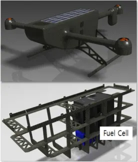
현재 개발 중인 연료전지 시스템을 적용하 기 위한 무인항공기는 프로펠러 형태의 트라 이콥터형으로 제작되어 수직이착륙 및 제자리 비행이 가능하고, 지상의 정보를 수집하는 정 찰 및 관측용 무인항공기이다. 다양한 임무수 행을 위한 무인항공기는 오랜 체공시간을 가 져야 함으로 소형․경량화 연료전지 시스템을 도입하였다. 무인항공기는 Fig. 1와 같이 연료 전지 시스템을 내부에 장착하고 무게중심을 고려하여 디자인하여 제작하였다.
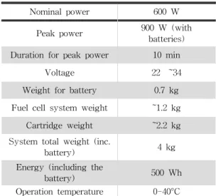
무인항공기의 작동 시 필요한 전원 (normal power), 최고 출력 (peak power), 전압, 배터 리 무게, 연료전지 시스템 무게, 수소 발생/저 장 시스템 무게, 단위시간당 전원 등의 고려사 항 등을 Table 1 에 나타내었다.
Fig. 1. A schematic of developing unmanned aerial vehicle by DGIST.
Nominal power 600 W
Peak power 900 W (with
batteries) Duration for peak power 10 min
Voltage 22 ~34
Weight for battery 0.7 kg Fuel cell system weight ~1.2 kg
Cartridge weight ~2.2 kg
System total weight (inc.
battery) 4 kg
Energy (including the
battery) 500 Wh
Operation temperature 0-40°C Table 1. The specifications developed for this study to
meet requirement for DGIST UAV
무인항공기를 위한 소형․경량화 연료전지 시스템은 수소 발생기를 장착한 시스템 과 수 소가스 탑재형의 두 가지 형태로 개발을 진행 하였다. 이 연구발표에는 수소 발생기 장착한 시스템의 성능 평가에 한해서 결과를 발표 하 고자 한다. 개발 중인 트라이콥터형 무인항공기 연료전지 시스템의 초 경량화를 위한 MBOP 설계 및 제작, 초 경량화 연료전지 부품 (End plates, Miniature values, Sensors, Pumps, System control electronics, reactor, and so on)을 NaBH₄ 카트리지를 이용해서 시스템 크기와 무게의 감소를 구현하였다.
연료전지 스택부분은 앞쪽 아랫면에 위치하 도록 설계하였고 팬을 통해서 공기를 양극 쪽 에 공급함으로 전기화학 반응이 일어남과 동 시에 냉각효과를 일으키도록 설계를 하였다 (Fig. 2). 연료전지 스택 뒤면 부분은 수소를 발 생 시키는 반응기 부분을 설치하였다 (Fig. 3).
수소 발생기를 장착한 시스템을 위하여 NaBH4 를 Fig. 2의 오른쪽 그림과 같이 연료탱크를 설치해서 연료를 저장을 하고 저장된 연료는
필요시 수소 발생 반응기 (hydrogen generation reactor)에 공급이 되어서 바로 수소가 두개의 팬이 달린 연료전지 스택에 공급되도록 설계 하였다. 그리고 초기 전원공급용으로 리튬이 온 배터리를 설치해서 초기 구동을 위한 전원 이 공급되도록 디자인하였다.
Fig. 2 A schematic of front view and top view of 600 W fuel cell system developed by DGIST
Fig. 3 A schematic of assembled stack and hydrogen generation system
Fig. 4에서는 연료전지 시스템의 Block Diagram 을 보여주고 있다. 주요 부품의 흐름도는 NaBH₄ 연료를 수소 발생 장치에 공급을 해서 수소를 공급 시키고, 발생된 수소는 600 W 연료전지 스택에 공급이 되고 발생된 전원이 무인 비행
기에 추진 전력으로 쓰이도록 설계를 하였다.
Fig 4. A 600 W fuel cell system block diagram by this study
3. 600 W급 연료전지의 제작 및 구동 결과
본 연구를 위해 제작한 초 경량화된 PEM 연료전지 시스템은 Ultra-light Fuel Cell System Part(Fig. 5)와 H₂Generator Reactor Cartridge Part (Fig. 6)으로 구성된다.
Fig 5. A Ultra-light Fuel Cell System Part of 600 W fuel cell system developed by DGIST
Fig 6. A H₂ Generator Reactor Cartridge Part of 600 W fuel cell system developed by DGIST
또한, 수소 발생기를 장착한 시스템을 위하 여 NaBH₄기반의 2가지 타입의 연료탱크 제 작하고 수소유량측정센서 및 컨트롤러와의 커 뮤니케이션 전용 알고리즘 개발하였다. 지속 적인 H₂변환정보와 이에 따른 유량의 변화 에 따라 조절되는 하이브리드 알고리즘을 설 계하였다.
3.1 PEMFC 스택의 운전 결과
본 연구에서 만들어진 스택 성능 평가실험 결과를 Fig. 7에서 보여주고 있다. 전류를 흐 르지 않는 Stack Open Circuit Voltage가 33 V가 나오고 있으며, 10 A∼15 A의 전류를 나 타낼 때 스택의 전압은 26 V를 유지함으로써 스택에서 나오는 전력은 350 W를 생산해 내 고 있다. 최대 출력을 확인하기 위해서 전류를 21 A∼28 A까지 증가시켰을 때 스택의 전압 은 23 V를 유지하면서 최대 전력은 630 W까 지 나타냄을 Fig. 7에서 보여주고 있다.
Fig. 7 The performance test for DGIST's developed stack. Stack=25℃ and NaBH4 supplied for hydrogen generation and air supplied by fans with open cathode design.
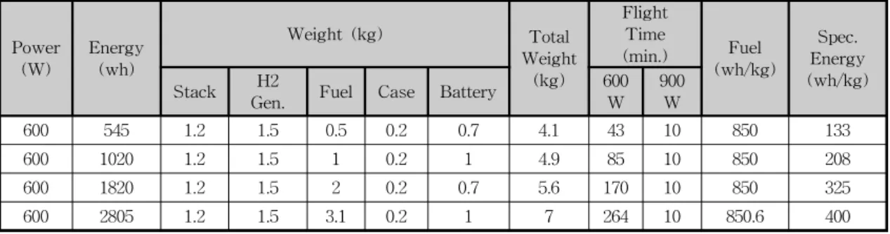
Table 2. Energy chart to show each components weight, energy, weight, flight time, and specific energy
Power (W)
Energy (wh)
Weight (kg) Total
Weight (kg)
Flight Time
(min.) Fuel
(wh/kg)
Spec.
Energy (wh/kg)
Stack H2
Gen. Fuel Case Battery 600
W 900
W
600 545 1.2 1.5 0.5 0.2 0.7 4.1 43 10 850 133
600 1020 1.2 1.5 1 0.2 1 4.9 85 10 850 208
600 1820 1.2 1.5 2 0.2 0.7 5.6 170 10 850 325
600 2805 1.2 1.5 3.1 0.2 1 7 264 10 850.6 400
Table 2에서는 각 부품들로의 무게, 총무게, 비행시간, 에너지 (wh), Power, Specific Energy (wh/kg)를 비교 분석을 통해 연구한 연료전 지 시스템을 성능을 분석하고자 한다. 총 비행 에 필요한 전원을 600 W 공급하기 위해서 전 원시스템의 각 부품들 무게는, 연료전지 스택 1.2 kg, 수소 발생장치 1.5 kg 이며, NaBH₄ 연료는 비행시간에 따라서 0.5 kg 에서 3.1 kg 증가됨에 따라서 비행시간을 43분에서 264분 까지 증대될 수 있도록 설계하였다.
본 연구에서 개발된 무인항공기에 들어가는 전원시스템은 최소 4 kg 이하의 시스템을 장 착함으로써 비행시간은 증가와 단위 무게 당 에너지 효율의 증대를 가능하게 하였다.
4. 결 론
본 연구에서는 무인항공기에 적용할 수 있 는 600 W급의 전원장치를 고분자 전해질 연 료전지 통하여 개발하였다. 연료전지 시스템
은 Ultra-light Fuel Cell System Part와 H₂ Generator Reactor Cartridge Part으로 제작 되었다. 개발된 연료전지 시스템은 전류를 21 A∼28 A까지 증가시켰을 때 스택의 전압은 23 V를 유지하면서 최대 전력은 630 W까지 나타내었다. 총 무게 4 kg의 전원장치로 약 1 시간가량의 정찰 활동을 할 수 있고, 연료량은 비행시간에 따라서 0.5 kg 에서 3.1 kg 증가됨 에 따라서 비행시간을 43분에서 264분까지 증 대될 수 있도록 설계하였다. 배터리만의 전력 공급으로 체공시간이 짧은 단점을 극복하고 최적의 전원공급이 될 수 있도록 새로운 디자 인의 초경량 전원공급 시스템을 개발하고 성 능 평가를 통한 검증을 수행하였다.
후 기
본 연구는 교육과학기술부에서 지원하는 대구경 북과학기술원 일반사업에 의해 수행되었습니다 (14-BD-01). This work was supported by the DGIST R&D Program of the Ministry of Education, Science and Technology of Korea(14-BD-01).
Reference
1. US Navy launches fuel cell powered UAV from underwater sub, Fuel Cells Bulletin, pp. 4, January, 2014
2. EnergyOr fuel cell powered UAV reaches 10 h flight endurance, Fuel Cells Bulletin, pp. 4-5, September, 2011
3. Seo J-E, Kim Y, Kim Y, Kim K, Lee JH, Lee DH, et al. Portable ammonia-borane-based H2 power-pack for unmanned aerial vehicles, Journal of Power Sources 254, pp. 329∼337, 2014 4. Kim J, Kim D-M, Kim S-Y, Nam SW, Kim T,
Humidification of polymer electrolyte membrane
fuel cell using short circuit control for unmanned aerial vehicle applications, International Journal of Hydrogen Energy, Vol. 39, pp. 7925∼7930, 2014
5. Frulla G, Cestino E. Design, Manufacturing and testing of a HALE-UAV structural demonstrator, Composite Structures, Vol. 83, pp. 143∼153, 2008
6. Protonex unveils PEM fuel cell power system for unmanned vehicles, Fuel Cells Bulletin. Vol. 2012, p.
3, September, 2012
7. Israel participating in European fuel cell aircraft project, Fuel Cells Bulletin, Vol. 2007, p. 9, 2007
8. Troncoso E, Lapeña-Rey N, Valero O, Solar-powered hydrogen refuelling station for unmanned aerial vehicles: Design and initial AC test results, International Journal of Hydrogen Energy, Vol. 39, pp. 1841∼1855, 2014
9. Zhang SS, Liquid electrolyte lithium/sulfur battery: Fundamental chemistry, problems, and solutions, Journal of Power Sources, Vol. 231, pp. 153∼
162, 2013
10. Kotobuki M, Munakata H, Kanamura K, Chapter 4.2 - All-Solid-State Li Battery for Future Energy Technology. In: Somiya S, editor. Handbook of Advanced Ceramics (Second Edition). Oxford:
Academic Press; 2013, pp. 343∼351, 2013 11. Kim T, NaBH4 (sodium borohydride) hydrogen
generator with a volume-exchange fuel tank for small unmanned aerial vehicles powered by a PEM (proton exchange membrane) fuel cell, Energy, Vol. 69, pp. 721∼727, May, 2014 12. Kim K, Kim T, Lee K, Kwon S, Fuel cell system with sodium borohydride as hydrogen source for unmanned aerial vehicles, Journal of Power Sources, Vol. 196, pp. 9069∼9075, 2011