Performance of Hot-dip Zn-6%Al-3%Mg Alloy Coated Steel Sheet as Automotive Body Material
Takeshi Shimizu1,†, Hiroshi Asada2, and Shigeru Morikawa2
1Surface Treatment Dept., Steel & Technology Development Labs., Nisshin Steel Co., Ltd.
5, Ishizu-nishimachi, Nishi-ku, Sakai-shi, Osaka 592-8332, Japan
2Forming Technology Dept., Steel & Technology Development Labs., Nisshin Steel Co., Ltd.
5, Ishizu-nishimachi, Nishi-ku, Sakai-shi, Osaka 592-8332, Japan (Received July 30, 2009; Revised March 26, 2010; Accepted March 27, 2010)
For the purpose of applying a hot-dip Zn-6mass%Al-3mass%Mg alloy coated steel sheet (ZAM) to automotive body materials, a laboratory study of the general properties required for inner and outer panels of automotive bodies was performed. Even with only light coating weight, ZAM showed an excellent corrosion resistance in terms of both cosmetic and perforation corrosion compared to the currently used materials for automotive bodies, GI70 and GA45. In our study, it was confirmed that ZAM exhibits as good as or better properties than GI70 in terms of spot weldability and press formability. Furthermore, since the same corrosion resistance can be achieved with less coating weight by applying ZAM, laser weldability is better than GI and GA.
Keywords : hot-dip, coating, ZAM, GI, GA, weldability, corrosion
†Corresponding author: [email protected]
1. Introduction
In 2000, Nisshin Steel started sales and production of a hot-dip Zn-6 mass% Al-3 mass% Mg alloy coated steel sheet ("ZAM") and has since then extended its applications to various purposes, including structural materials for pre- fabricated housings, road construction materials, agricul- tural materials and home appliances. Recently, due to its excellent corrosion resistance, ZAM is increasingly being employed in the field of automobile parts fabrication as well and, future application as an automotive body materi- al is expected.
With respect to automotive body materials, perforation corrosion caused by snow melting agents was regarded as a problem in 1980s North America and Scandinavia, and the use of galvanized steel sheets soon came to be widely adopted as a countermeasure.1) Furthermore, in conjunction with the extended period of warranty for auto- motive body corrosion, zinc coating weight has been increased.1) Meanwhile, due to laser welding being ac- tively introduced in automotive body assembly processes, and particularly in recent Europe,2) there has been an in- crease in the demand to reduce zinc coating weight for
improved weldability. To solve this issue, Zn-Mg alloy coated steels, for which high corrosion resistance can be expected for smaller coating weight, are being devel- oped,3),4) and in Europe, there is a movement to use it as an automotive body material.5)-7) Furthermore, it is pro- jected that zinc will become depleted by 2050,8) resulting in the acceleration of the movement toward reduced zinc coating weight used in automotive body materials.9),10) Our studies so far have revealed that with the same amount of coating, ZAM exhibits corrosion resistance sev- eral times better than the hot-dip galvanized steel sheets ("GI") and galvannealed steel sheets ("GA") currently used as automotive body materials.11) For this reason, by apply- ing ZAM, which needs only a relatively light coating, to automotive body materials, conservation of zinc resources and improvement of laser weldability can both be expected without lowering the corrosion resistance level. This paper reports the result of our study on how well ZAM performs as a material for inner and outer panels of an automotive body.
2. Test method
2.1 Specimen
Two types of ZAM produced in a continuous hot dip- ping line, with coated weights of 35 and 66 g/m2 per side
Table 1. Coating weight and mechanical properties of specimes used in this study
Specimen Symbol Coating weight (g/m2) YS (N/mm2) TS (N/mm2) EL (%) Hot-dip Zn-6%Al-3%Mg alloy coated
steel sheet
ZAM30 35 155 308 47
ZAM60 66 152 304 48
Hot-dip galvanized steel sheet GI70 83 176 324 45
Hot-dip galvannealed steel sheet GA45 51 168 308 46
("ZAM30" and "ZAM60", respectively) were used as specimens. Moreover, GI with a coated weight of 83 g/m2 per side ("GI70"), GA with a coated weight of 51 g/m2 per side ("GA45") were subjected to similar tests for comparison. Post-treatment was not applied to any of the specimens. The substrate for all specimens was 0.7 mm thick ultra-low carbon steel sheet with Ti added. Table 1 shows the mechanical properties of each specimen.
2.2 Paint coating performance
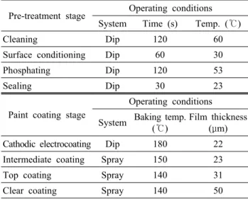
The paint coating performance of a set of specimens conforming to the Ford ESB-M2P130-A specifications was evaluated using three samples (n = 3) for each speci- men. Table 2 shows the paint coating conditions.
After phosphating, the surface morphology of each specimen was examined using a scanning electron micro- scope (SEM), and the coating weight of the phosphate film was measured by the weigh-strip-weigh method.
For evaluation of paint adhesion, fully painted speci- mens were exposed to a wet environment of 100% relative humidity and at a temperature of 38 °C for 120 hours.
The paint adhesion was measured by cross-hatching an area and peeling off any loose paint using adhesive tape.
To investigate cosmetic corrosion resistance, fully paint-
Table 2. Paint coating conditions
Pre-treatment stage Operating conditions System Time (s) Temp. (℃)
Cleaning Dip 120 60
Surface conditioning Dip 60 30
Phosphating Dip 120 53
Sealing Dip 30 23
Paint coating stage
Operating conditions System Baking temp.
(℃)
Film thickness (μm) Cathodic electrocoating Dip 180 22 Intermediate coating Spray 150 23
Top coating Spray 140 31
Clear coating Spray 140 50
ed specimens were prepared. After cross-scribing, these specimens then were subjected to 30 cycles of the Ford laboratory simulated Arizona Proving Grounds (APG) cor- rosion test,12) which ran 1 cycle per day for 5 days per week. The maximum width of creepback from the scribed line due to blistering was measured for each tested speci- men.
2.3 Perforation corrosion resistance
Perforation corrosion resistance was evaluated using the coupons created as shown in Fig. 1, which is recom- mended by the Society of Automotive Engineers, Inc.
(SAE)13) and using SAE J2334 cyclic corrosion test,12) op- erated 1 cycle per day for 5 days per week. Neither phos- phating nor painting was applied on the circular evaluation area of the coupon, while the rest of the area was covered with an electro-coat. This test was also done with triplicate coupons. The corrosion depth was measured with a point micrometer after removing the corrosion products formed on the evaluation area on coupons taken out of the cyclic corrosion test at 80, 120 and 160 cycles. Then the four maximum corrosion depth measurements (one per quad- rant) in each coupon were averaged.
Fig. 1. Coupon for perforation corrosion test.
ZAM30 GI70 GA45
C.W.*:2.4~2.6 g/m2 10 μm C.W. : 2.6~2.8 g/m2 C.W. : 5.2~5.3 g/m2
*C.W.: Coating weight of phosphate film
Fig. 2. Apperance and coating weight of phosphate film formed on each specimen.
2.4 Weldability and formability
The welding current range and electrode life were inves- tigated Fig. 1 Coupon for perforation corrosion test. using a single-phase AC stationary welder. A current range that is from the minimum current at which nuggets with diame- ter of 4√t [t = sheet thickness (mm)] can be obtained to the current at which expulsion occurs was defined as a proper welding current range. To investigate the elec- trode life, spot welding current was set to 1.4 times the minimum current at which 4√t nuggets can be obtained.
The nugget diameter was measured after every 100 welds.
When the size fell below 4√t, the electrode life test was terminated. The number of spots at that point was recorded as the electrode life of each specimen.
The laser weldability was tested using a YAG laser at a welding speed of 5 m/min. The specimens were laid on the top of each other without any space between sheets.
The welded zone was visually observed, and the number of weld defects (pits, blow-holes) was measured using X-ray photos.
To investigate the press formability, sheet specimens with press oil were experimentally formed into cups using a 196 kN hydraulic deep-drawing tester. The press form- ability of each specimen was evaluated by the range of blank holding force in which a drawn cup without wrinkles or rupture can be obtained.
3. Results
3.1 Paint coating performance
Fig. 2 shows the appearance and coating weight of phos- phate film formed on the surface of each specimen. On the surface of ZAM, it can be seen that fine crystallized phosphate film was formed, indicating good zinc phos- phating performance. Comparing with the GI and GA specimens, it is apparent that the crystal morphology of phosphate film on ZAM is similar to that on GI in terms
of crystal size and coating weight.
As shown in Fig. 3, the fully painted ZAM shows no loss of the paint film by tape pull after exposure to the wet environment of 100% relative humidity at 38 °C for 120 hours. This reveals that ZAM has good paint adhesion, equivalent to the GI, GA.
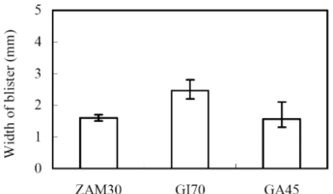
Fig. 4 shows the maximum width of blister from cross- scribed lines on fully painted specimens subjected to 30
10 mm
Fig. 3. Result of paint adhesion test afterexposure to wet environment (ZAM30).
Fig. 4. Maximum width of blister from cross scribed line of fully painted specimens subjected to 30 cycles of the Ford APGE corrosion test.(* Bar range indicates the range of maximum width of blister among 3 specimens)
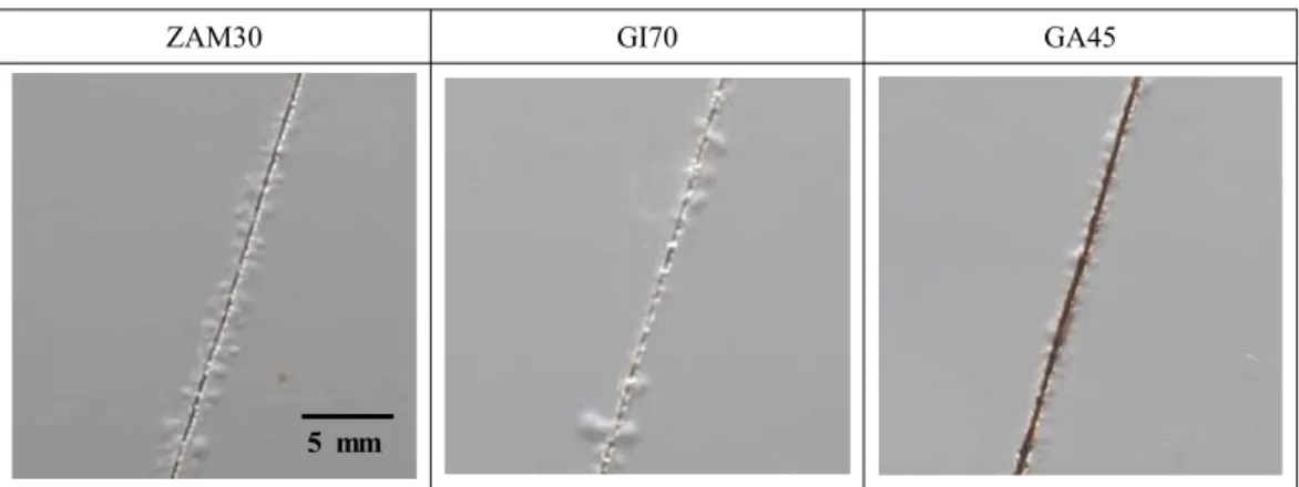
ZAM30 GI70 GA45
5 mm
Fig. 5. Appearance of cross scribed portion of fully painted specimens subjected to 30 cycles of the Ford APGE corrosion test.
ZAM30
ZAM60 (160 cycles) GI70 (80 cycles) GA45 (80 cycles) (80 cycles) (160 cycles)
10 mm
Fig. 6. Appearance of evaluation area of each coupon subjected to perforation corrosion test (SAE J2334).
cycles of the corrosion test. The maximum blister width on ZAM30 is smaller than that on GI70, and is equivalent to that on GA45. Fig. 5 shows the appearance of cross scribed portions. From these images, it can be seen that red rust occurred on the scribed portion on GA45. Among these specimens, the ZAM specimen has the lightest coat- ing weight but its blister width is as small as that on GA45 and it also showed resistance to red rust. Accordingly, the cosmetic corrosion resistance of ZAM30 is superior to those of GI70 and GA45 that are currently used for auto- motive bodies.
3.2 Perforation corrosion resistance
Fig. 6 shows the appearance of evaluation area (25 mm dia.) of each coupon after the perforation corrosion test.
The entire evaluation area of the GI70 and GA45 coupons are covered with red rust after only 80 cycles. Meanwhile, red rust has only formed sporadically in small spots on the ZAM30 coupon after 80 cycles. Even after 160 cycles, the majority of the rust generated is still white rust on the evaluation area of the ZAM30 and ZAM60 coupons, with spots of red rust just starting to appear. Less red rust has generated on the ZAM60 coupon, which has a heavier coating weight.
Fig. 7. Average corrosion depth in evaluation area of each coupon subjected to perforation corrosion test (SAE J2334).
(*Bar range indicates the range of average corrosion depth among 3 coupons)
Fig. 7 shows the result of measuring the average corro- sion depth after 80, 120 and 160 cycles of the perforation corrosion test. The corrosion of the GI70 and GA45 cou- pons had developed into through-holes between 80 and 120 cycles. The corrosion depths of the ZAM30 and
Electrode shape Dome type (φ6) Electrode material Cu-1%Cr alloy
Squeeze time 12 cycles (60Hz)
Electrode force 1.5 kN
Continuous spot welding method
Repeat the following:
continuous spot welding
of 20 points at 2-second intervals
⇔ stopping for 20 senconds
Fig. 8. Spot welding current range.
Fig. 9. Electrode life in continuous spot welding test.
ZAM60 coupons, on the other hand, are shown to be less than 0.05 mm even after 160 cycles. Thus, ZAM exhibits considerably superior resistance against perforation corro- sion compared to GI and GA.
3.3 Weldability and formability 3.3.1 Spot welding
Fig. 8 shows the welding current range of each speci- men. The spot welding current range of both ZAM30 and ZAM60 is higher than that of GA45 and is almost the same as that of GI70.
Fig. 9 shows the electrode life of each specimen. The result indicates the longest electrode life for the GA45.
When the ZAM and GI are compared, the ZAM30 is con- sidered to have a longer electrode life than the GI70, given its lighter coating weight. Comparison of the results of the ZAM60 and GI70, which have almost the same coating weight, shows that the electrode life for ZAM is slightly shorter than that for GI.
3.3.2 Laser welding
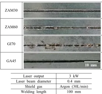
Fig. 10 shows the appearance of the specimens after laser welding, and Fig. 11 shows the number of weld defects. The effect of the coating weight is clearly seen
ZAM30
ZAM60
GI70
GA45 10 mm
Laser output 3 kW
Laser beam diameter 0.4 mm Shield gas Argon (30L/min) Welding length 100 mm
Fig. 10. Apperance of laser welded portion with lap joint (joint gap: 0mm).
Fig. 11. Number of weld defects (pit and blow-hole) in laser welded portion.
on both the appearance of the welded zone and the number of weld defects. The ZAM30, which had the lightest coat-
Rupture
Punch diameter 103 mm Die diameter 105 mm Punch shoulder radius 5 mm
Die shoulder radius 5 mm Drawing height 65 mm
Forming speed 60 mm/min
Fig. 12. Drawable condition range in cylindrical drawing test.
ing, exhibits good laser welding performance.
3.3.3 Press forming
Fig. 12 shows the drawable range of each specimen.
When the blank diameter is 230 mm, the drawable range of the ZAM30 and ZAM60 is equivalent to that of the GI70 and wider than that of the GA45. When the blank diameter is increased to 250 mm, the drawable range dis- appears for the GI70 and GA45, while both the ZAM30 and ZAM60 have wide drawable ranges. The coating layer of ZAM (about 150HV) is harder than that of GI, and it can be inferred that a wider drawable range can be ob- tained by using ZAM than by using GI, as the friction at the flange inflow can be kept low.
Although numerous cracks have generated in the coating layer when drawing into cups, the coating layer adheres firmly to the substrate, and no powdering can be observed.
Based on the above, ZAM is considered to be a coated steel sheet with excellent drawing stability at actual press forming.
4. Conclusions
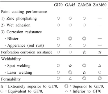
For the purpose of applying ZAM to automotive body materials, we investigated the general properties required for the inner and outer panels of automotive bodies. The summary of the quality characteristics of ZAM compared to GI70 is shown in Table 3. In terms of cosmetic corro- sion resistance and perforation corrosion resistance, ZAM shows an excellent corrosion resistance with lighter coat- ing compared to GI70 and GA45 that are currently being used for automotive body materials. Furthermore, it was confirmed that ZAM has spot weldability and press form- ability that are equal to or better than GI70. In addition, because of the coating weight, which relates to corrosion resistance, can be reduced, ZAM has higher laser weld- ability than GI and GA.
Accordingly, ZAM is expected to be a material that pro-
Table 3. The quality characteristics of ZAM for automotive body materials
GI70 GA45 ZAM30 ZAM60 Paint coating performance
1) Zinc phosphating ○ ○ ○ ―
2) Wet adhesion ○ ○ ○ ―
3) Corrosion resistance
․Blister ○ ◎ ◎ ―
․Apperance (red rust) ○ △ ○ ―
Perforation corrosion resistance ○ ○ ☆ ☆ Weldability
․Spot welding ○ ☆ ◎ △
․Laser welding ○ ◎ ☆ ○
Formability ○ △ ◎ ◎
☆:Extremely superior to GI70, ◎:Superior to GI70,
○:Equivalent to GI70, △:Inferior to GI70 vides a zinc-saving solution, excellent formability, and im- proved laser weldability, which are required in future auto- motive body materials.
References
1. M. R. Ostermiller, L. Singer, L. L. Piepho, and L.
Raymond, Proc. of 4th Int. Conf. on Zinc and Zinc Alloy Coated Steel Sheet, Chiba, Japan, 20, 678 (1998).
2. D. Petring, J. Jpn. Weld. Soc., 73, 539 (2004).
3. B. Scheffel, O. Zywitzki, and C. Metzner, Proc. of 7th Int. Conf. on Zinc and Zinc Alloy Coated Steel Sheet, Osaka, Japan, 18, 556 (2007).
4. M. Vlot, M. Zuijderwijk, M. Toose, L. Elliott, R. Bleeker, and T. Maalman, Proc. of 7th Int. Conf. on Zinc and Zinc Alloy Coated Steel Sheet, Osaka, Japan, 18, 574 (2007).
5. T. Koll, K. Ullrich, J. Faderl, J. Hagler, and A. Spalek, Proc. of 6th Int. Conf. on Zinc and Zinc Alloy Coated Steel Sheet, Chicago, IL, USA, 4, 803 (2004).
6. C. Schwerdt, M. Riemer, S. Köhler, B. Schuhmacher, and M. Steinhorst, Proc. of 6th Int. Conf. on Zinc and Zinc Alloy Coated Steel Sheet, Chicago, IL, USA, 4, 783 (2004).
7. R. Bleeker, F. Hannour, C. Goos, T. F. J. Maalman, S. M. Smith, M. J. Vlot, and W. Vrenken, Proc. of 7th Int. Conf. on Zinc and Zinc Alloy Coated Steel Sheet, Osaka, Japan, 18, 510 (2007).
8. National Institute for Mater. Sci. web site
9. J. Faderl, Proc. of 7th Int. Conf. on Zinc and Zinc Alloy Coated Steel Sheet, Osaka, Japan, 18, 14 (2007).
10. B. Schuhmacher, T. Heller, M. Steinhorst, and W.
Warnecke, Proc. of 7th Int. Conf. on Zinc and Zinc
Alloy Coated Steel Sheet, Osaka, Japan, 18, 397 (2007).
11. T. Shimizu, A. Andoh, H. Asada, and S. Morikawa, Society of Automotive Engineers World Congress, SAE Technical Paper No.2005-01-1330, Detroit, MI, USA (2005).
12. D. Davidson, L. Thompson, F. Lutze, B. Tiburcio, K.
Smith, C. Meade, T. Mackie, D. McCune, H. Townsend, and R. Tuszynski, Society of Automotive Engineers World Congress, SAE Technical Paper No.2003-01- 1238, Detroit, MI, USA (2003).
13. T. E. Dorsett and D. D. Davidson, Proc. of 6th Automotive and Corrosion Prevention Conf., Dearborn, Mich, USA, 4, 403 (1993).