Ⅰ. INTRODUCTION
Non-carious cervical lesions (NCCLs) are char- acterized by the loss of dental hard tissue at the
cemento-enamel junction (CEJ)1). The etiology and diagnosis of NCCLs remain controversial.
Previously, clinicians believed this to be caused solely by toothbrush abrasion, but presently many clinicians now classify this as tooth failure due to occlusal loading2-4). It has been suggested that occlusal loads cause the tooth to flex, particularly during lateral excursion. As the tooth flexes, ten- sile and shear stresses are generated in the cervi- cal region of the tooth that cause disruption of the
The influence of combining composite resins with different elastic modulus on the stress distribution of class V
restoration: A three-dimensional finite element study
Jeong-Kil Park1, Bock Hur1, Sung-Kyo Kim2*
1Department of Conservative Dentistry, School of Dentistry, Pusan National University, Busan, Korea
2Department of Conservative Dentistry, School of Dentistry, Kyungpook National University, Daegu, Korea
This study was to investigate the influence of combining composite resins with different elastic modulus, and occlusal loading condition on the stress distribution of restored notch-shaped non-cari- ous cervical lesion using 3D finite element (FE) analysis.
The extracted maxillary second premolar was scanned serially with Micro-CT. The 3D images were processed by 3D-DOCTOR. ANSYS was used to mesh and analyze 3D FE model. A notch-shaped cavity was modeled and filled with hybrid, flowable resin or a combination of both. After restora- tion, a static load of 500N was applied in a point-load condition at buccal cusp and palatal cusp.
The stress data were analyzed using analysis of principal stress.
Results showed that combining method such that apex was restored by material with high elastic modulus and the occlusal and cervical cavosurface margin by small amount of material with low elastic modulus was the most profitable method in the view of tensile stress that was considered as the dominant factor jeopardizing the restoration durability and promoting the lesion progression. [J Kor Acad Cons Dent 33(3):184-197, 2008]
Key words : Non-carious cervical lesion, Stress distribution, Composite resin, Elastic modulus, Finite element analysis
- Received 2008.3.5., revised 2008.4.3., accepted 2008.4.14. - ABSTRACT
* Corresponding Author: Sung-Kyo Kim Department of Conservative Dentistry
School of Dentistry, Kyoungpook National University, 188-1, Samduk 2ga, Jung-gu, Daegu, 700-412, Korea Tel: 82-53-420-5935
E-mail: [email protected]
※ This work was supported for two years by Pusan National University Research Grant.
bonds between the hydroxyapatite crystals, lead- ing to crack formation and eventual loss of enam- el and the underlying dentine5).
Grippo6) proposed a new classification of tooth structure loss called abfraction (from the Latin words ab - away, and fraction - breaking). He defined this as the pathologic loss of tooth sub- stance primarily caused by biomechanical loading forces resulting in flexure and failure of enamel and dentin at a location away from loading.
Clinically, abfraction lesions are wedge-shaped defects that are principally found on the buccal and labial aspects of the teeth. Once the lesion has been formed, the highest stress concentration was observed around the apex of the wedge- shaped lesion7).
NCCLs occur in a variety of forms depending on the type and severity of the etiological factor, but not all lesions require restorations8). The decision to restore NCCLs is based on the desire to strengthen the tooth and decrease the theoretical stress concentration and flexure, mitigate lesion progression, prevent hypersensitivity and pulp involvement, improve oral hygiene and enhance esthetics8,9). Treatment materials have included the restoration with resin-based composites, glass ionomers or a combination of these materials10,11).
Owing to the lack of inherent macromechanical retention in restorations of NCCLs, adhesion is the most important factor in retention of such restorations. However, the retention is affected by various factors such as tooth flexure, occlusal stress, the character of the dentinal surface and elastic modulus of the restorative materials. A clinical study with earlier generation adhesive systems showed that retention of restorations in NCCLs was influenced by the elastic modulus of the composite resin12).
Clinically, composite restorations are appreciat- ed for their esthetic qualities, relative wear resis- tance, and smooth surface texture. Recently, flowable resin was introduced. Due to the flexibil- ity of this material, it can be used to restore NCCLs. The combination of flowable and micro- filled or microhybrid composites combines the advantages of both materials13) and materials
combinations may be possible.
According to Park’s study14), when restoring the notch-shaped lesion, material with high elastic modulus worked well at the lesion apex and material with low elastic modulus worked well at the cervical cavosurface margin.
The finite element (FE) method has been widely used in biomechanics for evaluating interfacial relationships inside biomaterials or between restoration and tooth surface.
The purpose of this study was to investigate the influence of combining composite resins with dif- ferent elastic modulus, occlusal loading condition on the stress distribution of the restored notch- shaped NCCL using 3D FE analysis.
Ⅱ. MATERIALS AND METHODS 1. FE model
To develop a 3D FE model, an intact normal extracted human maxillary second premolar was used. The extracted premolar was scanned serial- ly with Micro-CT (SkyScan1072; SkyScan, Aartselaar, Belgium) to expose the tooth sections perpendicular to the long axis of the tooth (58 ㎛ in thickness) and parallel to the occlusal plane.
Image processing software, 3D-DOCTOR (Able Software Co., Lexington, MA, USA), was employed to make the boundaries of enamel, dentin and pulp and to construct a surface model of tooth from the sectioned two dimensional images. ANSYS (Swanson Analysis Systems, Inc., Houston, USA) was used to mesh and analyze 3D FE model.
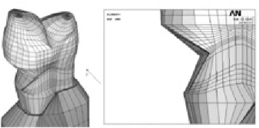
In this study, the final model consisted of 16,668 elements with 18,245 nodes. A notch- shaped lesion with a 4.28 ㎜ vertical height and a 5.31 ㎜ mesiodistal width was modeled. The mod- ified notch model was the same shaped lesion except for the rounded lesion apex (Figure 1).
The physical properties of the tooth and sup- porting structures used in this study are given in Table 1. All materials were assumed to be linear- ly elastic, homogeneous and isotropic.
The periodontal ligament was assumed to be 0.3
㎜ wide, and the dimensions of the surrounding compact and cancellous bone were derived from standard texts. Alveolar bone was also generated by growing the outer surface of the tooth model from 2 ㎜ below the CEJ and the cervical cavosur- face margin of the cavity15,16). The pulp was mod- eled as a void since previous researchers17) found that omission of the pulp has no influence on stress profiles. In these models, the outer surface and the base of the alveolar bone model was fixed in order to prevent rigid body motion for FE analysis. The model was also fixed on mesiodistal direction.
2. Restorations
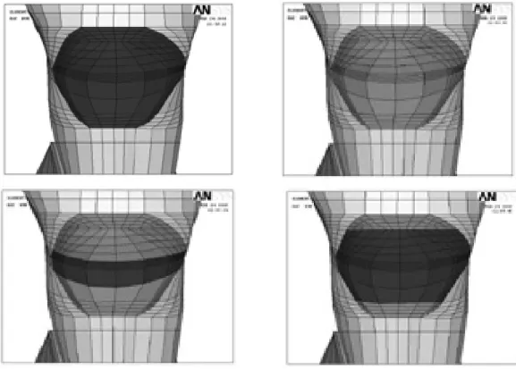
Notch cavities were filled with hybrid, flowable resin and combination of both (Figure 2). The data of material properties such as elastic modu-
lus, Poisson’s ratio and polymerization shrinkage were used by literature review18,20,21) (Table 2).
The Tetric Flow (Vivadent Ets., FL-9494-Schaan, Liechtenstein) and Z100 (3M Dental Products, St. Paul, MN, USA) were used as representatives of flowable and hybrid resin. The dentin bonding system used in this study was Scotchbond MP (3M Dental Products, St. Paul, MN, USA) and the adhesive layer thickness was 40 ㎛. The phys- ical properties of the tooth, supporting structures and materials used in this study are given in Table 1. The adhesive layer was made by math- ematical shell element modeling and the conjunc- tions between materials were set as complete cou- pling.
3. Loading conditions
The model was loaded with two vertical loads of Figure 1. 3 dimensional finite element model of notch shaped cavity.
Table 1.Mechanical properties of the tooth and supporting structures used in the study
Materials Mechanical properties
Young’s modulus (㎫) Poisson’s ratio (υ)
Enamel 84000a 0.33a
Dentin 18000a 0.31a
PDL 0.667b 0.49b
Cancellous bone 13700b 0.38b
Cortical bone 34000b 0.26b
a: Katona et al.18) b: Geramy et al.19)
Figure 2. Simulated restorations of notch-shaped NCCL (Upper left; Z100-dark brown, Upper right; Tetric Flow-light brown, Lower left; Combination 1, Lower right; Combination 2).
Table 2.Mechanical properties of the materials used in the study
Materials Mechanical properties
Young’s modulus (㎫) Poisson’s ratio (υ) Contraction stress (㎫)
Tetric Flow (T) 5300a 0.28a 23.5c
Z 100 (Z) 15200a 0.28a 7.6c
Scotchbond MP 1640b 0.28b -
a: Katona et al.18), b: Le et al.20), c: Kleverlaan et al.21)
Figure 3.Schematic diagram of loading points (A; Perpendicular load on the upper third of the palatal slope of the buccal cusp, B; perpendicular load on the upper third of the buccal slope of the palatal cusp).
500 N each, shown in Figure 3. Perpendicular load on the upper third of the palatal slope of the buccal cusp (Load A) and perpendicular load on the upper third of the buccal slope of the palatal cusp (Load B) were used.
4. Experimental groups
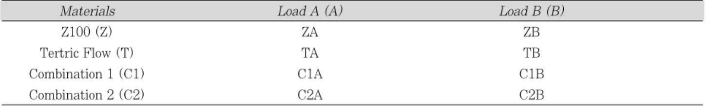
The variables were restoration methods (Tetric Flow; T, Z100; Z, Combination 1; C1, Combination 2; C2), and loading conditions (Load A; A or Load B; B).
Combination 1(C1) method was that apex was restored by small amount of Z100 and the occlusal and cervical cavosurface margin by large amount of Tetric Flow. Combination 2 (C2) method was that apex was restored by large amount of Z100 and the occlusal and cervical cavosurface margin by small amount of Tetric
Flow (Figure 2).
The tested groups were classified as 8 situations (Table 3).
5. Stress analysis
To explore the stress condition of the element, the principal stresses presented in the buccal cer- vical area were used. Under Load A, minimum principal stress was analyzed and under load B maximum principal stress was analyzed. The principal stresses are in fact normal stresses, act- ing on principal planes on which the shearing stresses are zero, and are found by using the existing six normal and shearing stress compo- nents rx, ry, rz, sxy, sxz and syz. If the absolute value of one principal stress of an element was larger than the other and positive, the element was determined to be in the tensile condition, if it
Table 3.Simulated groups according to cavity designs, restoration methods and loading conditions
Materials Load A (A) Load B (B)
Z100 (Z) ZA ZB
Tertric Flow (T) TA TB
Combination 1 (C1) C1A C1B
Combination 2 (C2) C2A C2B
Figure 4. Node selection (left) and magnified aspects (right) of mesial corner of notch-shaped lesion.
Along the cavity 4 lines, each 4 nodes were selected at the 3 areas (MP: Mesial point angle, DP: Distal point angle, M1: Nodes near mesial point angle, CEJ: Cemento-enamel junction, Occ: Occlusal cavosurface margin, DEJ: Dentino-enamel junction, Apex: Lesion apex).
was smaller than the others and negative, the element was determined to be in the compressive condition.
The principal stresses in the occlusal cavosur- face margin and dentino-enamel junction (DEJ) of occlusal wall, lesion apex, and cavosurface margin of cervical wall were analyzed using ANSYS.
6. Node selection for stress analysis
Nodes were selected according to cavity 4 line (occlusal cavosurface margin line, DEJ line, lesion apex line and cervical cavosurface margin line) with 3 areas (mesial, middle, distal) to compare stresses before and after restorations. At the ini- tial pilot study, the highest stress in the unre- stored cavity was observed at the mesial point angle (MP). After the cavity was restored with composite resin, the peak stress was moved to more proximal node than MP. Thus, an additional M1 node was selected (Figure 4).
7. Comparison with mechanical properties of teeth
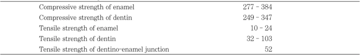
The obtained data were compared with the reported mechanical failure range of teeth22) (Table 4).
Ⅲ. RESULTS 1. Before restoration
General principal stress distributions before restoration were shown in Figure 5.
The peak compressive stress of 588.0 ㎫ was concentrated at MP under Load A and the peak
tensile stress of 193.3 ㎫ was concentrated at MP under Load B and these peak stresses were over the stress limit of teeth.
The lesion apex line stresses showed the largest stress value, followed by DEJ line, cervical cavo- surface margin line and occlusal cavosurface mar- gin line. Larger apex stresses were observed in the mesial area than in the distal area.
Principal stress distributions of 4 cavity line were shown in Figure 6.
2. After restoration
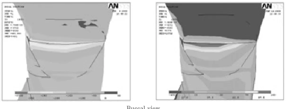
General compressive and tensile stress distribu- tions were shown in Figure 7. After restoration, significant stress relief was shown in the all cavi- ty areas, especially at the lesion apex. However, stress concentration at the mesial corner was still observed as unrestored cavity.
Under Load A, stress relief was smaller than other restoration methods when the entire cavity was restored by Tetric Flow (TA) at the lesion apex.
Under Load B, In C2B, stress relief was the largest at the lesion apex and mesial root dentin.
Peak stresses were shown in Table 5.
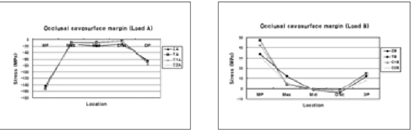
(1) Occlusal cavosurface margin
On occlusal cavosurface margin, generally simi- lar compressive stress was seen independently of restorations under Load A (Figure 8). The high- est compressive stress of 152.5 ㎫ was concentrat- ed at MP in C1A under Load A. In ZA, the lowest compressive stress of 142.7 ㎫ was concentrated at MP. These two stresses were within the limit stress of tooth.
In case of tensile stress, there were a lot of dif-
Table 4.Mechanical failure range of teeth22) (㎫)
Compressive strength of enamel 277 - 384
Compressive strength of dentin 249 - 347
Tensile strength of enamel 10 - 24
Tensile strength of dentin 32 - 103
Tensile strength of dentino-enamel junction 52
ferences of stress value according to restorations at MP. The highest tensile stress of 47.5 ㎫ was concentrated at MP in TB under Load B. In C2B, the lowest tensile stress of 31.3 ㎫ was concen- trated at MP. As there were a lot of quantities of Tetric Flow (TB, C1B), stresses were developed at MP.
(2) DEJ
On occlusal DEJ, like the occlusal cavosurface margin, similar compressive stress was seen inde- pendently of restorations under Load A (Figure 9). The highest and lowest compressive stress value and site under Load A were the same as in
the occlusal cavosurface margin.
Under Load B, the peak stress value and site were the same as in the occlusal cavosurface mar- gin. However, the stress pattern was different.
Two stress reduction patterns were shown. As there was a lot of Tetric Flow (TB, C1B), the peak stress was increased at MP, but stresses were steeply decreased in the middle and distal area.
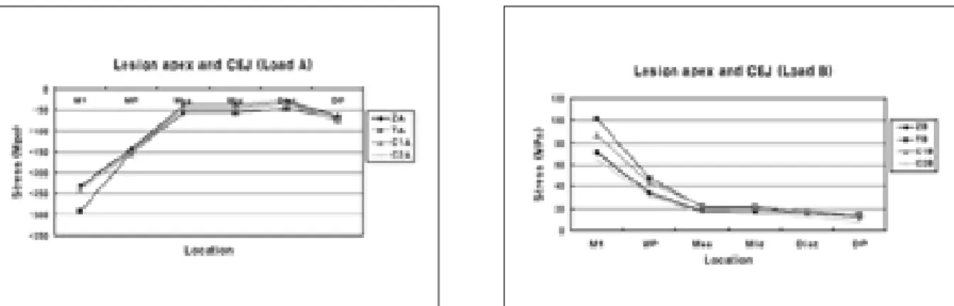
(3) Lesion apex and CEJ
On the lesion apex and CEJ, similar compres- sive stresses except peak stress value were observed in all restorations under Load A. The Figure 5. Principal stress distribution of notch-shaped cavity before restoration (Left; Minimum principal
stress-Compressive stress, Right; Maximum principal stress-Tensile stress. Upper and lower view’s scales were different each other).
Figure 6. The compressive and tensile stress distribution on occlusal cavosurface margin (Occlusal), DEJ, lesion apex and CEJ (Apex & CEJ), cervical cavosurface margin (Cervical) under Load B (MP: Mesial point angle, DP: Distal point angle, Mes: Mesial node, Mid: Middle node, Dist: Distal node).
Buccal view
Table 5.Peak stresses of each locations under Load A and B
Load A Load B
Experimental Groups (compressive stress) (tensile stress)
㎫ (node location) ㎫ (node location)
Unrestored notch cavity -588.0 (MP) 193.3 (MP)
Z100 (Z) -232.0 (M1) 70.7 (M1)
Tetric Flow (T) -291.4 (M1) 101.6 (M1)
Combination 1 (C1) -238.9 (M1) 87.2 (M1)
Combination 2 (C2) -240.7 (M1) 64.9 (M1)
ZA TA C1A C2A
ZB TB C1B C2B
Figure 7. The Principal stress distribution under Load A and B.
Figure 8. The compressive and tensile stress distribution on occlusal cavosurface margin after restoration under Load B (MP: Mesial point angle, DP: Distal point angle, Mes: Mesial node, Mid: Middle node, Dist: Distal node).
Figure 9. The compressive and tensile stress distribution on occlusal DEJ after restoration under Load B (MP:
Mesial point angle, DP: Distal point angle, Mes: Mesial node, Mid: Middle node, Dist: Distal node).
Figure 10. The compressive and tensile stress distribution on lesion apex and CEJ after restoration under Load B (MP: Mesial point angle, DP: Distal point angle, Mes: Mesial node, Mid: Middle node, Dist: Distal node).
Figure 11. The compressive and tensile stress distribution on cervical cavosurface margin after restoration under Load B (MP: Mesial point angle, DP: Distal point angle, Mes: Mesial node, Mid: Middle node, Dist: Distal node).
peak stress site shifted from MP to M1 (Figure 10). The highest compressive stress of 291.4 ㎫ was concentrated at M1 in TA under Load A. In ZA, the lowest compressive stress of 232 ㎫ was concentrated at M1.
Under Load B, the peak stress site also moved from MP to M1. The highest tensile stress of 101.6 ㎫ was concentrated at M1 in TB. In C2B, the lowest tensile stress of 64.9 ㎫ was concen- trated at M1. In whole lesion apex and CEJ line, the greatest tensile stress relief was observed in C2B.
(4) Cervical cavosurface margin
On cervical cavosurface margin, the highest and lowest compressive stress value and site under Load A were same as at occlusal cavosurface mar- gin. At the middle site, in ZA, compressive stress- es were larger than others (Figure 11).
Under Load B, the stresses were reduced mov- ing from the MP to DP. Stress declines were all different. The highest tensile stress value and site were same as occlusal cavosurface margin.
Similarly, at the lesion apex and CEJ, the best tensile stress relief was observed in C2B.
Ⅳ. DISCUSSION
NCCLs vary in size, shape, and most impor- tantly, the cause from which they have resulted.
Some clinicians have hypothesized that wedge- shaped noncarious cervical lesions are caused pri- marily by tooth flexure as a consequence of mal- occlusion, bruxism, and parafunctional habits2-4).
Once the lesion was formed, the highest stress concentration was observed around the apex of the wedge-shaped lesion7). The discontinuity of the enamel and dentin may cause increased stress and damage in the enamel23). The severity of geo- metric discontinuity of NCCL can be expected to have strong influence on the development of internal stress in teeth24). In our experiment, the stresses converged in the apex line with more mesial side under both loading conditions. These asymmetric patterns of mesial stress distribution were related to the anatomical asymmetry of the
teeth.
When clinically assessing NCCLs, dental practi- tioners must consider if the cervical defect requires a restoration and if so, which restorative material will provide the best outcome.
Additionally, the clinician must consider a modu- lus of elasticity, resistance to wear and ability to withstand acid dissolution9,25). A number of researchers have reported controversies regarding restoration of class V cervical lesions8,10,11). Recently resin composites with dentin bonding agents have become a popular for the restoration of NCCLs26). In the current experiment, lesions were restored by conventional hybrid resin and flowable resin.
Important factor affecting retention failure is the elastic modulus of the restorative materials.
It has been demonstrated that a strong correla- tion exists between marginal failure and Young’s modulus of the composite restoration material in the class V situation27). It is a general rule of engineering that stress will always follow the path of the stiffest material, that is, the path with the highest elastic modulus. In the case of an intact tooth, the stiffest material is the enam- el, and an applied occlusal load is generally passed through the enamel and into the underly- ing dentine, with the load being dissipated through the crown and down into the root in a radial and apical direction28).
Therefore, strictly from a mechanical point of view, it can be said that the best approach is to apply restorative materials with high Young’s modulus as possible. Yaman et al.29) concluded that for class V applications Z 100 gives the most promising results. According to Nakayama et al.30) a Young’s modulus equal to or greater than that of the dentine is required for resin composite to resist deformation by occlusal stress. In addition, resin composite Z 100 has a high Young’s modu- lus and a high percentage of volume fraction filler, which increases resistance to deformation by occlusal force31). When using a hard material, the stiffest restoration-tooth interface resulted in the lowest restoration displacement.
In contrast, some researchers contend that one
of the methods used to maximize the retention rates of class V restorations is the placement of low elastic modulus materials. Heymann and col- leagues32) reported that the retention rates for restorations of a material with lower elastic mod- ulus were significantly higher than those of a material with higher elastic modulus. The ratio- nale behind this is that high modulus materials are unable to flex when the tooth structure is deformed under load and therefore they are dis- placed from the cavity. In contrast, low modulus materials can flex with the tooth and therefore can remain in situ. Thus, these resins will absorb much of the masticatory stresses rather than transferring it to the dentin-restoration inter- face11). A low elastic modulus also contributes to stress relief from polymerization shrinkage of composites, preserving the marginal integrity of restorations33). This property allows for good wet- ting along the cavity walls, which improves the adaptation of the restorative material.
In the current study, two different elastic modu- lus materials were used. The stress values after restoration were different at the 4 lines depending on the elastic modulus of the materials. The high- est stress reduction was observed at the apex in the Z100 restoration which had the higher elastic modulus. In the other 3 lines, especially at the cervical cavosurface margin, Tetric Flow restora- tion showed a smaller stress value compared with Z100. Therefore, the combination of flowable and conventional hybrid composites may offer a syner- gistic effect of both materials. It was hypothesized that Z100 composites used as a strut would improve the reduction rates of stress in the apex.
This hypothesis was based on earlier studies29) showing that restoration using Z100 worked as a strut to prevent stress concentration of the lesion.
Under Load A, similar compressive stress was observed independently of kind of combination restorations. However, under Load B, different stress values appeared. As there was a lot of Tetric Flow, stresses were greater at the apex, but stresses were smaller at the other 3 lines.
Z100 was reversed. These results show that high elastic modulus materials work well at the lesion
apex. This is also involved with special feature of notch-shaped cavity. Due to its sharpest geomet- rical discontinuity, stress was focused on the lesion apex in the notch-shaped cavity. When bit- ing force is applied, a high elastic modulus mater- ial like as a strut can sustain the stress at the apex. This is especially true under Load B when tensile stress occurs.
In this experiment, C2 method was the best method for tensile stress reduction. The cavity apex was restored by a combination method such that apex was restored by Z100 and the occlusal and cervical cavosurface margin by small amount of Tetric Flow. Thus, this method is recommended for restoration of notch-shaped lesion because it showed the best effect in tensile stress.
Experimental in vitro dental stress studies of abfraction generally have employed two methods:
photoelastic stress models and FE analysis. In the present study, a 3D FE method has been used to calculate the stress field in directly paced class Ⅴ composite restorations. A direct, quanti- tative comparison between the stresses generated by these techniques has been made. Two-dimen- sional axisymmetric finite element modeling has been used in most previous research22,23,28). Although numerical results can be easily obtained in two dimensional modeling, it has some signifi- cant shortcomings. Because the shape of a human tooth is highly irregular, it can not be represented in a two-dimensional space and the actual loading can not be simulated without taking three dimen- sions into consideration. Therefore, three-dimen- sional modeling with the actual dimension is pre- ferred for a reliable analysis.
The result of this study must be interpreted with a certain amount of caution. First, it was hard to include all factors that occur intraorally in this computer simulation. Therefore, some sim- plification was used. Second, this study compared finite element models assuming one to have an isotropic enamel and dentin, but the real tooth model was an anisotropic enamel and dentin mod- el. Third, these static load stresses may not reflect the actual conditions encountered intrao- rally, therefore may not adequately describe the
functional movement of occlusion.
Further research is needed to assess the mecha- nism through which noncarious cervical lesions are initiated and propagated, as well as the potential role of abfraction. Such investigations will include intervention studies with occlusal therapy to investigate whether eliminating occlusal loading factors prevents formation, pro- gression of cervical lesions and loss of restorative material. Our future investigations will also include studies of other restoration methods as well as optimal materials of stress induced cervi- cal lesions.
Ⅴ. CONCLUSIONS
Within the limitations of this study, it is con- cluded that when restoring notch-shaped NCCL, combining method such that apex was restored by material with high elastic modulus and the occlusal and cervical cavosurface margin by small amount of material with low elastic modulus was the most profitable method in the view of tensile stress that was considered as the dominant factor jeopardizing the restoration durability and pro- moting the lesion progression.
REFERENCES
1. Levitch LC, Bader JD, Shugars DA, Heymann HO.
Non-carious cervical lesion. J Dent 22:195-207, 1994.
2. Litonjua LA, Bush PJ, Andreana S, Tobias TS. Effects of occlusal load on cervical lesion. J Oral Rehabil 31:225-232, 2004.
3. Telles D, Pegoraro LF, Pereira JC. Prevalence of non- carions cervical lesions and their relation to occlusal aspects: a clinical study. J Esthet Dent 12:10-15, 2000.
4. Palamara D, Palamara JE, Tyas MJ, Messer HH.
Strain patterns in cervical enamel of teeth subjected to occlusal loading. Dent Mater 16:412-419, 2000.
5. Lee WC, Eakle WS. Possible role of tensile stress in etiology of cervical erosive lesions of teeth. J Prosthet Dent 52:374-80, 1984.
6. Grippo JO. Abfractions: A new classification of hard tissue lesions of tooth. J Esthet Dent 3:14-19, 1991.
7. Kuroe T, Caputo AA, Ohata N, Itoh H. Biomechanical effects of cervical lesions and restoration on periodon- tally compromised teeth. Quintessence Int 32:111-118, 2001.
8. King PA. Adhesive techniques. Br Dent J 186:321- 326, 1999.
9. Osborne-Smith KL, Burke FJ, Wilson NH. The aetiolo-
gy of the non-carious cervical lesion. Int Dent J 49:139-143, 1999.
10. Vandewalle KS, Vigil G. Guidelines for the restoration of class V lesions. Gen Dent 45:254-260, 1997.
11. Leinfelder KF. Restoration of abfracted lesions.
Compendium 15:1396-1400, 1994.
12. Heymann HO, Sturdevant JR, Bayne S, Wilder AD, Sluder TB, Brunson WD. Examining tooth flexure effects on cervical restorations: a two-year clinical study. J Am Dent Assoc 122:41-47, 1991
13. Loguercio AD, Zago C, Leal K, Ribeiro NR, Reis A.
One-year clinical evaluation of flowable resin liner associated with a microhybrid resin in noncarious cer- vical lesions. Clin Oral Invest 9:18-20, 2005.
14. Park JK Hur B, Kim SK. Stress distribution of class V composite resin restorations: A three-dimensional finite element study.J Kor Acad Cons Dent 33:28-38, 2008.
15. Lindehe J, Karring T. Textbook of Clinical Periodo- ntology. 2nd edition, Munksgaard, Copenhagen, p19- 69, 1989.
16. Schroeder HE, Page RC. Periodontal Diseases. 2nd edition, Lea & Fabiger, Philadelphia, p3-52, 1990.
17. Rubin C, Krishnamurthy N, Capilouto E, Yi H. Stress analysis of the human tooth using a three-dimensional finite element model. J Dent Res 62:82-86, 1983.
18. Katona TR, Winkler MM. Stress analysis of a bulk- filled class V light-cured composite restoration. J Dent Res 73:1470-1477, 1994.
19. Geramy A, Sharafoddin F. Abfraction: 3D analysis by means of the finite element method. Quintessence Int 34:526-533, 2003.
20. Le SY, Chiang HC, Huang HM, Shih YH, Chen HC, Dong DR, Lin CT. Thermo-debonding mechanisms in dentin bonding systems using finite element analysis.
Biomaterials 22:113-123, 2001.
21. Kleverlaan CJ, Feilzer AJ. Polymerization shrinkage and contraction stress of dental resin composite. Dent Mater 21:1150-1157, 2005.
22. Litonjua LA, Andreana S, Patra AK, Cohen RE. An assessment of stress analyses in the theory of abfrac- tion. Biomed Mater Eng 14:311-321, 2004.
23. Dejak B, Mlotkowski A, Romanowicz M. Finite element analysis of mechanism of cervical lesion formation in simulated molars during mastication and parafunction.
J Prosthet Dent 94:520-529, 2005.
24. Kuroe T, Itoh H, Caputo AA, Konuma M.
Biomechanics of cervical tooth structure lesions and their restoration. Quintessence Int 31:267-274, 2000.
25. Lee WC, Eakle WS. Stress-induced cervical lesions:
review of advances in the past 10 years. J Prosthet Dent 75:487-494, 1996.
26. Neo J, Chew C, Yap A & Sidhu S. Clinical evaluation of tooth-colored materials in cervical lesions. Am J Dent 9:15-17, 1996.
27. Kemp-Scholte CM, Davidson CL. Marginal integrity related to bond strength and strain capacity of compos- ite resin restorative systems. J Prosthet Dent 64:658- 664, 1990.
28. Rees JS, Hammadeh M. Undermining of enamel as a mechanism of abfraction lesion formation: a finite ele- ment study. Eur J Oral Sci 112:347-352, 2004.
29. Yaman SD, Sahin M, Aydin C. Finite element analysis of strength characteristics of various resin based restorative materials in class V cavities. J Oral Rehabil
30:630-641, 2003.
30. Nakayama WT, Hall DR, Grenoble DE, Katz JL.
Elastic properties of dental resin restorative materials.
J Dent Res 53:1121-1126, 1974.
31. Willems G, Lambrechts P, Braem M, Celis JP, Vanherle G. A classification of dental composites according to their morphological and mechanical char- acteristics. Dent Mater 8:310-319, 1992.
32. Heymann HO, Sturdevant JR, Bayne S, Wilder AD, Sluder TB, Brunson WD. Examining tooth flexure effects on cervical restorations: a two-year clinical study. J Am Dent Assoc 122:41-47, 1991.
33. Braga RR, Hilton TJ, Ferracane JL. Contraction stress of flowable composite materials and their efficacy as stress-relieving layers. J Am Dent Assoc 134:721-728, 2003.
탄성계수가 다른 복합레진의 혼합수복이 5급 수복물의 응력분포에 미치는 영향에 관한 3차원 유한요소법적 연구
박정길1∙허 복1∙김성교2*
1부산대학교 치의학전문대학원 치과보존학교실, 2경북대학교 치의학전문대학원 치과보존학교실
본 연구는 3차원 유한요소분석법적 연구를 통해 쐐기형 비우식성 치경부병소의 복합레진수복에서 다른 탄성계수를 가 진 복합레진의 혼합수복이 5급 수복물의 응력분포에 미치는 영향에 대해 알아보고자 하였다.
발거된 상악 제2소구치를 Micro-CT로 스캔한 후 3D-DOCTOR로 3차원유한요소 모형을 제작하였다. 제작된 소구치 모형에 쐐기형 와동과 변형시킨 와동을 형성하고 각 와동을 탄성계수가 서로 다른 혼합형 복합레진 또는 흐름성 복합레 진으로 수복하였다. 수복 전, 후 협측교두와 설측교두에 500N의 하중을 가한 후 응력분포를 ANSYS 프로그램을 이용 하여 주 응력 분석법으로 평가한 결과 치아 및 수복물에 위해한 인장응력을 고려할 때 탄성계수가 높은 재료로 와동저 선각을 수복하고 교합측변연과 치경부측 변연은 탄성계수가 낮은 재료로 수복하는 혼합수복법이 쐐기형 비치경부병소 의 수복에 있어 가장 유리하였다.
주요어: 비우식성 치경부병소, 응력분포, 복합레진, 탄성계수, 유한요소분석 국문초록