Introduction
A tomotherapy unit delivers radiation therapy plans using a helical tomotherapy technique. A linear accelerator is mounted on a ring gantry that continuously rotates while the patient is translated along the axis of gantry rotation during treatment delivery. The beam has fan geometry and 64 leaf binary collimators areused to subdivide this fan beam into beamlets. Intensity modulation is achieved by a temporal modulation of the collimator leaves. The unit is designed for intensity modulated treatment delivery and therefore the traditional requirement of a flat radiation field across the treatment field does not exist anymore. The tomotherapyunit takes advantage of this and a field
flattening filter is omitted. The advantage of this design is a relatively high machine output and a radiation field that varies less in energy across the field.1) Therefore, conventional dosimetry methods as well as 3D water phantom are not applicable to this unit.
The aim of this study is to develop the efficient dosimetry tool using scintillation screen for helical tomotherapy. In this study cylindrical water phantom was fabricated with scintillation screen to acquire the cumulated doses during irradiation and studied its feasibility.
Methods and Materials
1. Phantom design
A cylindrical phantom with a scintillation screen (LANEX Fast Screen, Kodak, USA) was designed to verify the real-time dose distribution of the tomotherapy. The
고신대학교 의과대학 학술지 제 권 제 호23 4 Kosin Medical Journal
Vol. 23. No. 4, pp. 128 131, 2008∼
Tae Sig Jeung, Sang wook Lim
Department of Radiation Oncology, Kosin University College of Medicine, Busan, Korea
――― Abstract ――――――――――――――――――――――――――――――――――――――――
Background: To develop the efficient dosimetry tool using scintillation screen for helical tomotherapy. In this study cylindrical water phantom was fabricated with scintillation screen to acquire the cumulated doses during irradiation and studied its feasibility.
Methods and Materials: A cylindrical phantom with a scintillation screen (LANEX Fast Screen, Kodak, USA) was designed to verify the real-time dose distribution of the tomotherapy. The scintillation screen was placed axially in the cylindrical water-filled phantom and faced toward the lens of the charge-coupled device (CCD) camera. The CCD camera captured the fluorescent light from the screen during the irradiation. The computer corrects and integrates the frames for measuring 2D dose distributions. Three types of targets were planed and treated at 10 Gy by the tomotherapy. The dose distributions from the fluorescent images were compared with the calculated dose distributions from the TPS.
Results and Discussion: In order to minimize the blurring in the images, the spread function was obtained from the profile of point dose and every pixel was deconvoluted by the blurring kernel. The blurring kernel could be expressed as two error functions. Comparison between the dose distributions from the fluorescent images with the calculated dose distribution from the TPS showed a good agreement at over 80% of isodose lines. The pixel value depends on the number of frames. And the dose depends on the number of frames. It is obvious the curve of dose versus pixel value is linear.
Conclusion: A real-time 2D dosimetry using the scintillation screen and the CCD camera is respected to be useful to verify the dose distribution of the tomotherapy.
―――――――――――――――――――――――――――――――――――――――――――――――――
Key words : Tomotherapy, Scintillation screen, Dose distribution
교신저자 임 상 욱:
주소 : 602-702 부산광역시 서구 암남동34번지 고신대학교 의과대학 방사선종양학교실 TEL : 051-990-6393
E-mai l: [email protected]
Dosimetric Evaluation of Tomotherapy using a Scintillation Screen
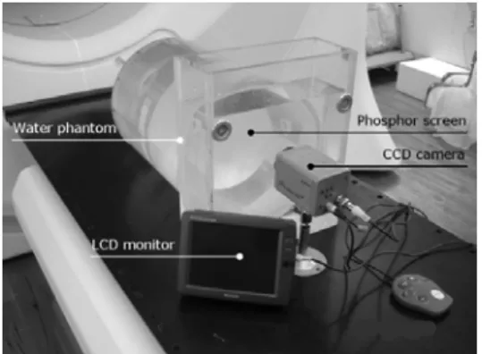
scintillation screen was placed axially in the cylindrical water-filled phantom and faced toward the lens of the charge-coupled device (CCD) camera as shown fig. 1. The rounded scintillation screen emits visible light during irradiation.2,3) The intensity of visible light depends on the dose rate and the energy of the radiation. Clear water on either side of the screen provided 20 cm of side scatter.
The CCD camera was used to capture the fluorescent light from the screen through the optical glass window of the phantom during irradiations from the tomotherapy unit.
Fig. 1. Home-made cylindrical water phantom for tomotherapy: The scintillatin screen placed axially in the phantom and the CCD camera faced to the screen. The LCD monitor is used to check the focus and the setup of the phantom and the CCD camera.
2. Image processing
The scintillation screen was exposed to the 6 MV photon beam from the linac and the tomotherapy. The CCD camera captured the fluorescent light from the screen at 30 frames per second during the irradiation. The motion imagesfrom the CCD camera were sent to the frame grabber and the images were digitized into MPEG2 format as 720×480 pixel size and 8 bit gray scale in real-time.
The computer corrects and integrates the frames for measuring 2D dose distributions (Fig. 2).
Fig. 2. Every frame were corrected in the software developed in this study and integrated. This figure shows the example of
the C-typed target.
3. Calibration for dose rate dependency and blurring effect Cylindrical water phantom without the scintillation screen was irradiated 6 MV photon beam to subtract the background which caused by light leakage and CCD of the camera itself. In order to obtain the correction factors for the dose rate, the scintillation screen in the phantom was calibrated at the reference conditions at SAD 80 cm with 10×10 cm field size for linac, center of the gantry ring with 5×40 cm2field size for the tomotherapy. The energy dependency was investigated by measuring the depth dose and irradiating of various photon energies. Increasing the dose rate from 100 MU/min to 900 MU/min at 100 MU/min step, the frames were integrated and measured the pixel values at the same depth. The dose rate dependency was applied to each frame. V0 is pixel value without blurring effect andV is measured pixel value. The blurring kernel (k) was obtained by Gaussian fitting as following,
k V V = 0 ⊗ ,
2
1 Erf
Erf
k= × ,
dr e
Erf
r 037 . 0
) 157 . 0 (
1
2
2 137 . 0
1 ∞ − −
∞
∫−
= π ,
dr e
Erf
∫−∞∞ r
− −
= 0.003
) 030 . 0 ( 2
2
2 043 . 0
1
π .
The deconvolution of the Gaussian function was applied to the pixel values of each frame before they reconstructed.
4. Comparing between measurements and calculations The virtual targets were assumed to be in the CT images of the phantom, which were planned and treated. There are three types of target, one is one spot target, another is C-shaped target, and the other is multiple targets. Each target was planed to be treated at 10 Gy by treatment planning system (TPS) of tomotherapy (Fig. 3). The cylindrical phantom was placed on the tomotherapy table and irradiated as calculations of the TPS. Every frame was
고신대학교 의과대학 학술지 제 권 호24 4 , 2008
integrated and the doses were calculated in pixel by pixel.
The point dose was measured with an ion chamber in the phantom to convert the relative dose to absolute one. The
dose distributions obtained from the scintillation screen were compared with those calculated from the TPS. During irradiation, the fluorescent light captured by the CCD camera (30 fps) was transferred to the computer to be analyzed and displayed. The dose distributions from the fluorescent images were compared with the calculated dose distribution from the TPS. The discrepancies were evaluated as gamma index for each treatment.
Results
Figure 4 shows the profile of point dose to be used for fitting the spread function curve to obtain theblurring kernel. The dose rate dependency curve is showing in figure 5. The pixel values were measured versus the dose rates from 100 MU/min to 900 MU/min at the reference condition. The solid line is the measurement and the dotted line is the fitting curve.
Comparison between the dose distributions from the fluorescent images with the calculated dose distribution from the TPS showed a good agreement at over 80% of isodose lines (Fig. 6). The maximum error of the isodose curves was less than 8 mmrelative to the calculated isodose curves.
0 0.2 0.4 0.6 0.8 1
-50 -40 -30 -20 -10 0 10 20 30 40 50
Off Axis (mm)
Relative dose
Fig. 4. Profile of point dose with scintillation screen for obtaining blurring kernel (k).
Fig. 5. Dose rate dependency; the relative pixel values were measured versus dose ratesfrom 100 MU/min to 900 MU/min.
The solid line and the dotted line are the measurement and the fitting, respectively.
0.0E+00 5.0E+05 1.0E+06 1.5E+06 2.0E+06 2.5E+06 3.0E+06 3.5E+06 4.0E+06 4.5E+06
0 200 400 600 800 1000
Dose rate (MU/min)
Relative pixel value
Fig. 6. Three cases of virtual targets were compared between the calculated and the measured dose distribution. (A), (B), and (C) are overlaid isodose lines for single target, C-shpaed target, and multiple targets, respectively. (D), (E), and (F) are the results of gamma index evaluation of comparison between calculations and measurements for three types of target. The dose distribution in high dose region matches well relatively.
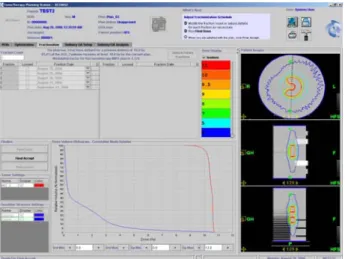
Fig. 3. Screen shot of treatment planning of C-shaped target:
Three types of target; one spot target, C-shaped target, multiple targets were planned and irradiated, respectively.
Each target was planed to be treated at 10 Gy by TPS of tomotherapy.
Dosimetric Evaluation of Tomotherapy using a Scintillation Screen
Discussion
The pixel value depends on the number of frames. And the dose depends on number of frames (30 frames equal to 1 second). It is obvious the curve of dose versus pixel value is linear. Therefore, the linearity correction for dose versus pixel value was not needed.4)
The curve for dose rate versus pixel value wasnot saturated until 900 MU/min. It is enough to use the scintillation screen for measuring the dose of therapeutic radiation.
The energy dependency in this system was ignorable.
It seems that the dose distribution error between the calculation from the TPS and the measured by this system was caused by light scattering effect in the water. Further study will be focused on the light scattering effect in the water.
Conclusion
2D dose distributions of the other slices in the phantom could be evaluated by moving the scintillation screen or the phantom in a longitudinal direction.
A real-time 2D dosimetry using the scintillation screen and the CCD camera is respected to be useful to verify the dose distribution of the tomotherapy. Further study will be focused on the 3D dosimetry of the tomotherapy by fixing the phantom on the floor, not the moving table.
국문초록
목적 고감도형광판을 이용하여 차원적 토모테라피의: 2
선량분포를 실시간으로 얻을 수 있는 정도관리(quality 장치의 개발 및 평가를 하고자 한다
assurance, QA) .
방법 인체와 흉부 및 복부의 크기와 유사한 직경: 25 cm 의 물로 차있는 원통형 팬톰에 고감도형광판을 횡방향 으로 삽입하여 토모테라피 선량측정용 팬톰 (axial plane)
을 제작하였으며 여기에
(phantom) CCD (charge-coupled
카메라를 부착하여 방사선조사시 형광판에서 발 device)
생되는 가시광선에 의한 영상을 얻었고 영상이 가지고 있는 세기정보를 계산하여 픽셀 값에 따른 선량분포를
실시간으로 확인하였다 토모테라피를 이용하여 종류의. 3
가상 표적에 대한 치료를 각각 수행하여 형광판으로부터 얻은 등선량곡선을 치료계획장치에서 계산된 등 선량곡 선과 비교하였다.
결과 선량당 빛의 세기의 관계그래프를 이용하여 형광:
판과CCD의 감도 보정을 위한 커널(kernel)을 구하였는
데 두 에러함수의 곱으로 표현할 수 있었다 토모테라피.
에서 형광판으로 측정한 등선량곡선과 치료계획장치에
서 계산된 등선량분포 비교결과80%이상의 선량에서 잘
일치하였다.
결론 본 연구에서 개발한 차원 선량계를 이용하여 물팬: 2
톰에서 선량과 빛의 세기와의 관계 및 방사선 조사시간 과 빛의 양의 관계를 찾을 수가 있었고 세기조절방사선
치료QA를 위한 실시간 평면선량계로서의 사용 가능성
을 보였다.
References
1) Welsh JS, Patel RR, Ritter MA, Harari PM, Mackie TR, Mehta MP :Helical tomotherapy: an innovative technology and approach to radiation therapy. Technol Cancer Res Treat 1(4):311-6, 2002
2) Lim S, Yeo IJ, Kim DY, Ahn YC, Huh SJ : Application of an Imaging Plate to relative dosimetry of clinical x-ray beams.
Kor J Med Phys 11(2):117-122, 2000
3) Lim S, Yi BY, Ko YE, Ji YH, Kim JH, Ahn SD, Lee SW, Shin SS, Kwon SI, Choi EK : Feasibility Study of the Real-Time IMRT Dosimetry Using a Scintillation Screen. J Korean Soc Ther Radiol Oncol 22(1):64-68, 2004
4) Li JS, Boyer AL, Ma CM : Verification of IMRT dose distributions using a water beam imaging system. Med Phys 28:2466-2474, 2001