Nomenclature
J : current density, mA/cm
2V : voltage, V
FF : fill factor
N : conversion efficiency, %
Subscript
BET : Brunauer-Emmett-Teller theory DSSC : dye-sensitized solar cells ITO : indium tin oxide
N719 : cis-bis (isothiocyanato) bis (2,2'-bipyridyl-4,4'- dicarboxylato) -ruthenium (II) bistetrabutylammonium
PEG : polyethylene glycol PET : polyethylene terephthalate SEM : scanning electron microscopy TCO : transparent conductive oxide TNTs : TiO
2nanotubes
1. Introduction
DSSCs have attracted much attention as promising alternatives to conventional solar energy conversion devices because of their low production cost and high energy conversion efficiency
1). However, conventional DSSCs have several inherent disadvantages associated with the use of glass substrates for electrodes, which restrict the applications of DSSC.
Flexible DSSCs based on plastic substrates are lightweight, thin, and pliable. They can be produced at low cost and can be easily integrated in a curved form, suitable for portable and wearable applications. The major problem regarding the development of flexible DSSCs based on plastic substrates is that they should be sintered at low temperatures due to a thermal degradation of plastics at sintering temperatures of approximately 500°C
2). Without sintering at high temperatures, the interconnection between TiO
2particles would be poor, resulting in poor performance of the cell. From this point of view, metal substrates provide alternatives for plastic substrates because of their wider compatibility with a far higher range of annealing temperatures
3)and improve electrical conduction by several orders of magnitude in comparison with a TCO layer
4,5).
Kang et al. reported a flexible DSSC assembled with stainless steel sheet as substrate and Pt-coated ITO/PET as the counter
Improved Conversion Efficiency of Dye-sensitized Solar Cells Based on TiO 2 Porous Layer Coated TiO 2 Nanotubes on a Titanium
Mesh Substrate as Photoanode
Jae-Min Lim ․ Weizhen He ․ Hyung-Kook Kim* ․ Yoon-Hwae Hwang*
Department of Nano Materials and Engineering and BK21 Plus Nano Convergence Technology Division, Pusan National University, Miryang 627-706, Republic of Korea
ABSTRACT: We report here flexible dye-sensitized solar cells (DSSC) based on Ti-mesh electrodes that show good mechanical flexibility and electrical conductivity. TiO
2nanotube arrays prepared by electrochemical anodizing Ti-mesh substrate were used as photoanode. A Pt-coated Ti-mesh substrate was used as counter electrode. The photoanodes were modified by coating a TiO
2porous layer onto the TiO
2nanotubes in order to increase the specific surface area. To increase the long term stability of the DSSCs, a gel type electrolyte was used instead of a conventional liquid type electrolyte. The DSSC based on 33.2 μm long porous TiO
2nanotubes exhibited a better energy conversion efficiency of ~2.33%, which was higher than that of the DSSCs based on non-porous TiO
2nanotubes.
Key words: Dye-sensitized solar cell, Porous TiO
2nanotubes, Specific surface area, Gel electrolyte
*Corresponding author: [email protected], [email protected] Received November 22, 2013; Revised December 6, 2013;
Accepted December 11, 2013
ⓒ 2013 by Korea Photovoltaic Society
This is an Open Access article distributed under the terms of the Creative Commons Attribution Non-Commercial License (http://creativecommons.org/licenses/by-nc/3.0)
which permits unrestricted non-commercial use, distribution, and reproduction in any medium, provided the original work is properly cited.
90
electrode owing to the opacity of the stainless steel sheet
3). However, DSSCs based on a metal sheet type photoanode must be illuminated from the back side, leading to a decrease in light harvesting and hence in conversion efficiency. To overcome this opacity issue, we used a Ti-mesh substrate for the photoanode since the voids in the mesh substrate allow light to enter the cell from the photoanode side which allows front illumination of cells.
Considerable effort has been devoted to the development of more efficient photoanode structures. In particular, one-dimensional TNT arrays have been received great attentions for unique properties that exhibit superiority in electron transport that allows decreasing the loss of electrons by recombination
6-8). Among many methods, TNTs prepared by the anodization method
9-11), which have by far the most remarkable properties, can be made by anodic oxidation of titanium in fluoride-based baths.
In this paper, TNTs on a Ti-mesh substrate were prepared by electrochemical anodization for photoanode, and Pt-coated Ti-mesh was used as for the counter electrode. TNTs grown on the Ti-mesh substrate are oriented in all directions, ranging from parallel to perpendicular to incoming photons, which would contribute to the light harvesting. In addition, to increase the specific surface areas of TNTs, we coated TNTs on the Ti-mesh substrates with a porous TiO
2layer. One of the manufacturing challenges for DSSCs has been the need for a robust sealing process that would prevent the liquid electrolyte in the cells from leakage and evaporation. To resolve this problem, we used a gel-type electrolyte. DSSCs assembled with the porous TNTs as photoanodes exhibited higher energy conversion efficiencies than those assembled with non-porous TNTs.
2. Experimental
The meshes made of commercially pure grade 1 titanium (99.5 wt% Ti) were purchased from Unique Wire Weaving (Hillside, NJ). In this experiment, a 100-mesh wire cloth woven from 0.002 in (51 μm) diameter wire with an open area of 64%
was used. The Ti-mesh cloth was cleaned and degreased ultrasonically in acetone and methanol followed by drying in a nitrogen stream. Electrochemical anodization was carried out in a two-electrode cell using a DC power supply (Agilent E3612A) with the Ti-mesh as anode and the graphite plate as cathode. The
electrodes were placed in a solution containing 0.3 wt% NH4F (98% purity, Sigma-Aldrich) and 2 vol % H
2O in ethylene glycol (99.8% purity, Sigma-Aldrich). Anodization was performed at a constant potential of 60V at 20°C, and the growth time was varied from 4 to 7 h. Subsequently, the samples were sonicated in methanol for 1 min. Thermal annealing was carried out at 500
°C in air for 1 h, and the TNTs obtained were then dip-coated with a porous TiO
2precursor. The synthesis of the porous TiO
2precursor was carried out using PEG (MW = 2000) as the template and Ti (OBu
n)
4as the inorganic source. The detailed methodology of synthesis has been published elsewhere
12). After dip-coating, samples were heat-treated at 550 °C with a heating rate of 1°C /min for crystallization of the TiO
2and removal of the template PEG. The resulting porous TNTs were immersed overnight in a dye solution of 0.5 mM N719 (Solaronix S. A.) in ethanol and then rinsed with ethanol to remove non-chemisorbed dye. The counter electrode was fabricated by coating the Ti-mesh substrate with a thin layer of a solution of 5 mM H
2PtCl
6in ethanol and heating at 450°C for 30 min.
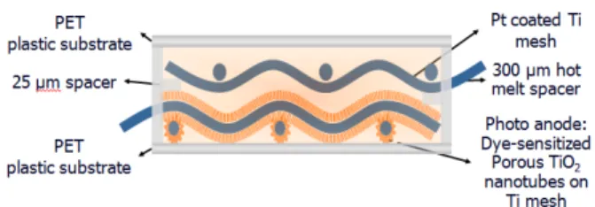
Subsequently, the sensitized photoanode was sandwiched together with the counter electrode using several pieces of 100 μm hot-melt polypropylene spacer. The gel electrolyte (Dyesol, EL-SGE) was spread on the electrodes. Completed electrodes were sealed between two transparent flexible polyethylene PET films. The connections to the anode and cathode were made to the unanodized part of the photoanode and a section of the counter electrode that extended beyond the edges of the PET films. For comparison, a DSSC based on original TNTs, without coating with porous TNTs, was fabricated in the same manner. A schematic of the all mesh type DSSC is provided in Fig. 1.
The morphologies of samples were examined using a SEM (Hitachi-S4700). The specific surface areas of original and porous TNTs were determined by the nitrogen adsorption- desorption isotherms. Measurements were performed at 65 K and the specific area of samples was calculated using BET equation. The amount of adsorbed dye concentration was
Fig. 1. The composition of the DSSC with Ti-mesh based electrodes
measured by using the solution of 0.1M NaOH and ethanol (1:1 in volume fraction), in which the anchored dye from dyed- electrodes was desorbed. The absorption spectrum was analyzed by an UV-Vis spectrophotometer (CARY 5,000, Varian, Inc.).
The current density-voltage (J-V) characteristics of the DSSCs were measured under AM 1.5 simulated illumination with an intensity of 100mW/cm
2(PEC-L11 model, Pecell Technologies Inc.). The intensity of sunlight illumination was calibrated using a standard Si photodiode detector with a KG-5filter. The J-V curves were recorded automatically with a Keithley SMU2400 source meter by illuminating the DSSCs.
3. Results and Discussion
The FESEM images of the original and porous TNTs on Ti-mesh substrates are provided in Fig. 2. Figs. 2(a) and (b) show low-magnification SEM images of the TNTs/mesh photoanode.
After anodization, the mesh retained sufficient voids to allow light to enter cells from the photoanode side leading to possible front illumination. The TNTs grew perpendicularly to the surface of the titanium wire and covered the entire wire uniformly. Figs.
2(g)-(i) show the lengths of the TNTs obtained with different growth times, which were 13.4, 18.3, and 33.2 μm after 4, 5, and 7h of anodization, respectively. The inner diameters of TNTs retained a constant value of approximately 100nm. In the Fig.
2(b), cleavage was observed at the all surfaces, which was derived from the curvature of the round-shaped titanium wire.
Figs. 2(c)-(f) show FESEM images of the original and porous TNTs. The tube walls of the original TNTs (Fig. 2(c): top view,
Fig. 2(d): side view) were smooth, whereas the tube walls of the porous TNTs (Fig. 2(c): top view, Fig. 2(e): side view) were rough. This rough surface is expected to enhance dye-loading because it increases the specific surface areas.
Fig. 3 shows the BET curves of the original and porous TNTs.
All samples exhibited type IV isotherms with type H3 hysteresis (Fig. 3), which is indicative of mesoporous materials
13). As shown in Fig. 3, the adsorption curve gradually increased in the middle-pressure region and exhibited abruptly in the high- pressure region (> 0.9 P/P
0). The adsorption behavior of TNTs can be attributed to the capillary condensation and multilayer adsorption of nitrogen in the mesopores or macropores
14). Our BET measurements indicated that 11.4, 18.3, and 33.2 μm long porous TNTs had specific surface areas of 103.75, 121.88, and 129.44 m
2/g, respectively, that is greater than those of original TNTs (81.65, 92.92, and 118.00 m
2/g). The high specific surface area is desirable for dye adsorption. A high BET surface area cannot be obtained from original TNTs with smooth tube walls and would be realized by the unique morphology of porous TNTs.
Fig. 4 presents the UV-vis absorption of dye solutions formed by the desorption of dye from the dye-sensitized electrode using 0.1 M NaOH aqueous solution. Table 1 shows the calculated amount of dye molecules which was calculated from UV-vis absorption spectra of desorbed sensitizers using the extinction coefficient of the N719 sensitizer. As comparing with the original TNTs photoanodes, it was evident that the porous TNTs photoanodes has higher dye adsorption due to a higher specific surface area of porous TNTs for anchoring sufficient dye molecules.
Fig. 2. The low-magnification SEM images of the top view (a) and cross-section (b) of TNTs on the Ti-mesh substrate. SEM images of original TNTs (c), (d) and porous TNTs (e), (f). Cross-section SEM images of TNTs anodized for 4 h (g), 5 h (h), 7 h (i)
Fig. 3. The nitrogen adsorption-desorption isotherms of the original and porous TiO2 nanotubes. P0 here is the saturation vapor pressure of liquid nitrogen
Fig. 4. The UV-visible spectra of original and porous TiO2 nanotubes
The J-V characteristics of DSSCs based on original and porous TNTs are shown in Fig. 5 and the key parameters are
summarized in Table 2. The increase of the J
scwith increasing tube length is quite obvious. Compared with the DSSC based on the porous TNT arrays of 13.4 μm tube length, DSSCs based on the 18.3 μm and 33.2 μm long porous NTs respectively showed a 12% and 31% elevation in J
sc. This improvement is naturally ascribable to the enlargement in the contact area between the TNTs and the dye. The 33.2 μm long original TNTs based DSSC fabricated without porous layer, exhibited an open circuit voltage (V
oc) of 0.719 V, a current density (J
sc) of 5.86 mAcm
-2, a fill factor (FF) of 0.51 and an efficiency (η) of 2.14%. The 33.2 μm long porous TNTs based DSSC resulted in improved performance, with J
scof 6.43 mAcm
-2, Voc of 0.720 V, FF of 0.50, and η of 2.33%, which represents about a 9% enhancement compared to the former cell due to the enhancement of Jsc. It is ascribed to the attachment of more dye molecules and therefore an increased number of electrons emitted from dyes excited by the incident light and then injected into the conduction band of the TiO
2. This is consistent with our BET measurements, which showed that porous TNTs had a higher specific surface area (129.44 m
2/g) than the original TNTs (118.00 m
2/g). Therefore, the photoanode made of porous TNTs is proved to possess higher dye adsorption ability than the one made of original TNTs with the same length of nanotubes.
To understand the correlation between the improved cell performance and the internal resistances of the DSSCs, we measured the electroch emical impedance spectra. Fig. 6 shows the Nyquist plots of the DSSCs made of the original porous TNTs electrodes measured under 100 mW/cm
2illumination at an open-circuit condition. Each Nyquist plot is composed of three semicircles, which correspond to (1) the electrochemical
Table 1. The specific surface area and dye adsorption values oforiginal and porous TiO2 nanotubes
Photo electrode SBET
(m2/g) Dye adsorbed (nmol/cm2)
O-TNTs (13.4 μm) 81.65 83
P-TNTs (13.4 μm) 103.75 113
O-TNTs (18.3 μm) 92.95 98
P-TNTs (18.3 μm) 121.88 131
O-TNTs (33.2 μm) 118.00 130
P-TNTs (33.2 μm) 129.44 143
Fig. 5. The current-voltage curves of DSSCs based on porous and original TiO2 nanotubes under AM 1.5G solar illumination
Table 2. The performance data of DSSCs based on porous and original TiO2 nanotubes
Photo
electrode Voc (V) Jsc(mA/cm2) FF η (%) O-TNTs
(13.4 μm) 0.717 4.056 0.51 1.48
P-TNTs
(13.4 μm) 0.699 5.154 0.50 1.80
O-TNTs
(18.3 μm) 0.693 4.616 0.53 1.71
P-TNTs
(18.3 μm) 0.707 6.034 0.50 2.14
O-TNTs
(33.2 μm) 0.719 5.863 0.51 2.14
P-TNTs
(33.2 μm) 0.720 6.430 0.50 2.33
reaction at the Pt counter electrode, (2) the charge transfer resistance at electrolyte/dye/metal oxide interface, and (3) the charge transport in the metal oxide layer and Warburg diffusion process, from the left to the right of the plot
15-18). However, neither of the DSSCs showed the additional third semicircle representing Warburg diffusion, resulting from reduced ion mobility. As the electrolyte and counter electrode are the same in all the materials, our primary interest is in the second semicircle (Z
2), which focuses on the TiO
2/dye/electrolyte interface.
The diameters of the second semicircles of the porous TNTs are smaller than that of original TNTs. This means that the charge transfer resistances of porous TNTs are smaller than that of original TNTs. Therefore, DSSC based on porous TNTs has
higher J
scdue to lower charge transfer resistances than DSSC based on porous TNTs at theTiO
2/dye/electrolyte interface.
4. Conclusions
In the present study, Ti meshes were utilized as both photoanode and counter electrode substrates. Mesh type DSSCs have several unique advantages, such as the availability of front illumination and low sheet resistance. We successfully fabricated TNTs with a porous TiO
2coating on Ti-mesh photoanodes and applied it into flexible DSSCs. The TiO
2porous layers on nanotube walls effectively improved specific surface areas. The improved amount of absorbed dye molecules on the porous walls of TNTs resulted in an increase of short-circuit current and hence the promotion in DSSCs performances. The cell based on the 33.2 μm porous TNTs/Ti photoanode exhibited the best performance of 2.33 %.
Acknowledgments
This work is supported by the National Research Foundation of Korea (Grant No. 2012R 1A1B3001357). Special thanks should be given to Professor Soo-Hyung Kim for offering us efficiency measurement of our DSSCs.
References
1. O’Regan, B., Gratzel, M., “A low-cost, high-efficiency solar cell based on dye-sensitized colloidal TiO2 films,” Nature, 353 737, 1991.
2. Li, Y. L., Lee, D. Y., Min, S. R, Cho, H. N., Kim, J., Chung, C.
W., “Effect of Oxygen Concentration on Properties of Indium Zinc Oxide Thin Films for Flexible Dye-Sensitized Solar Cell,”
Jpn. J. Appl. Phys., 47 6896, 2008.
3. Kang, M. G., Park, N. G., Rye, K. S., Chang, S. H., Kim, K. J.,
“A 4.2 % efficient flexible dye-sensitized TiO2 solar cells using stainless steel substrate,” Sol. Energy Mater. Sol. Cells, 90 574, 2006.
4. Onoda, K., Ngamsinlapasathian, S., Fujieda, T., Yoshikawa, S., “The superiority of Ti plate as the substrate of dye-sensitized solar cells,” Sol. Energy Mater. Sol. Cells, 91 1176, 2007.
5. Toivola, M., Halme, J., Miettunen, K., Aitola, K., Lund, P. D.,
“Nanostructured dye solar cells on flexible substrates,” Int. J.
Energy Res., 33 1145, 2009.
6. Mora-Sero, I., Fabregat-Santiago, F., Denier, B., Bisquert, J., Tena-Zaera, R., Elias, J., Levy-Clement, C., “Determination of Fig. 6. The electrochemical impedance spectra of dye-sensitized
solar cells based on original and porous TNTs
carrier density of ZnO nanowires by electrochemical techni- ques,” Appl. Phys. Lett., 89 203117, 2006.
7. Snaith, H. J., Schmidt-Mende, L., “Advances in Liquid-Electrolyte and Solid-State Dye-Sensitized Solar Cells,” Adv. Mater., 19 3187, 2007.
8. Fabregat-Santiago, F., Barea, E. M., Bisquert, J., Mor, G. K., Shankar, K., Grimes, G. A., “High Carrier Density and Capacitance in TiO2 Nanotube Arrays Induced by Electrochemical Doping,”
J. Am. Chem. Soc., 130 11312, 2008.
9. Beranek, R., Hildebrand, H., Schmuki, P., “Self-Organized Porous Titanium Oxide Prepared in H2SO4/HF Electrolytes Corrosion, Passivation, and Anodic Films,” Electrochem. Solid- State Lett., 6 B12, 2003.
10. Gong, D., Grimes, C. A., Varghese, O. K., Hu, W., Singh, R.
S., Chen, Z., Dickey, E. C., “Titanium oxide nanotube arrays prepared by anodic oxidation,” J. Mater. Res., 16 3331, 2001.
11. Zwilling, V., Darque-Ceretti, E., Boutry-Forveille, A., “Anodic oxidation of titanium and TA6V alloy in chromic media. An electrochemical approach,” Electrochim. Acta, 44 921, 1999.
12. He, W. Z., Qiu, J. J., Park, S. J., Lee, J. H., Kim, Y.D., Kim, H.
K., Hwang, Y. H., “The Fabrication of TiO2 Mesoporous Thick Films by Employing a Pre-Embedded ZnO Nanorods Support,”
J. Nanosci. Nanotechnol., 9 7145, 2009.
13. Sing, K. S. W., Everett, D. H., Haul, R. A. W., Moscou, L.,
Pierotti, R. A., Rouquerol, J., Siemieniewska, T., “Reporting physisorption data for gas/solid systems with special reference to the determination of surface area and porosity,” Pure Appl.
Chem., 57 603, 1985.
14. Li, F., Wang, Y., Wang, D., Wei, F., “Characterization of sin- gle-wall carbon nanotubes by N2 adsorption,” Carbon 42 2375, 2004.
15. Kern, R., Sastrawan, R., Ferber, J., Stangl, R., Luther, J.,
“Modeling and interpretation of electrical impedance spectra of dye solar cells operated under open-circuit conditions,”
Electrochim. Acta, 47 413, 2002.
16. Adachi, M., Sakamoto, M., Jiu, J., Ogata, Y., Isoda S.,
“Determination of Parameters of Electron Transport in Dye- Sensitized Solar Cells Using Electrochemical Impedance Spectroscopy,” J. Phys. Chem. B, 110 13872, 2006.
17. Hsu, C. P., Lee, K. M., Huang, J. T. W., Lin, C. Y., Lee, C. H., Wang, L. P., Tsai, S. Y., Ho, K. C., “EIS analysis on low tem- perature fabrication of TiO2 porous films for dye-sensitized so- lar cells,” Electrochim. Acta, 53 7514, 2008.
18. Wu, J. J., Chen, G. R., Lu, C. C., Wu, W. T., Chen, J. S.,
“Performance and electron transport properties of TiO2 nano- composite dye-sensitized solar cells,” Nanotechnology, 19 105702, 2008.