한국인에서 대퇴 후상과간 각의 측정
- 삼차원 전산화단층촬영과 자기공명영상을 이용한 각의 비교 -
울산대학교 의과대학 강릉아산병원 정형외과학교실
최영준ㆍ황재광ㆍ이기원ㆍ전주식ㆍ최지호
= 국문초록 =
목적: 슬관절 전치환술시 대퇴 삽입물 회전에 흔히 이용되는 대퇴 후상과간 각(대퇴 상과간 축과 대퇴 후과간 축 간의 각)을 자기공명영상 및 삼차원 전산화단층촬영에서 측정하였으며, 한국인에서의 차이점을 규명하고자 하였다.
대상 및 방법: 자기공명영상 검사를 시행한 257례와 삼차원 전산화단층촬영을 시행한 118례의 슬관절을 대상으로 하였다.
자기공명영상 검사에서는 임상적 대퇴 후상과간 각을 측정하였고, 삼차원 전산화단층촬영의 경우 임상적 및 수술적 대퇴 후상과간 각을 모두 측정하였다.
결과: 자기공명영상 검사에서 임상적 대퇴 후상과간 각은 남자 5.56도, 여자 5.81도(평균 5.66도)이였다. 삼차원 전산화단 층촬영의 경우 임상적 대퇴 후상과간 각은 남자 5.48도, 여자 5.85도(평균 5.55도)이였으며, 수술적 대퇴 후상과간 각은 남자 3.68도, 여자 4.02도(평균 3.74도)이였다. 삼차원 전산화단층촬영으로 측정한 임상적 대퇴 후상과간 각과 자기공명영상으로 측정한 값 및 남녀간 값의 통계학적 의미는 없었다(p>0.05).
결론: 자기공명영상과 삼차원 전산화단층촬영에서 측정한 임상적 대퇴 후상과간 각은 차이가 없었으며, 슬관절 전치환술 시 적절한 회전 정렬을 잡기 위한 기준으로 사용되는 대퇴 후과간 축에 대한 대퇴 삽입물의 3도 외회전은 한국인에서는 부족할 수 있다고 사료되었다.
색인단어: 대퇴골, 자기공명영상, 삼차원 전산화단층촬영, 대퇴 후상과간 각
통신저자: 황 재 광
210-711, 강원도 강릉시 사천면 방동리 415번지 강릉아산병원 정형외과
TEL: 033-610-3249, FAX: 033-641-0805 E-mail: [email protected]
서 론
슬관절 전치환술에서 대퇴 삽입물의 회전 정렬을 맞추는 것은 슬개 - 대퇴 관절의 안정성 및 슬관절 굴곡 시 내외측 간의 안정을 유지하는데 매우 중요하다2,14,16). 대퇴골의 적 절한 회전 정렬을 얻기 위해 그 기준이 되는 선은 양측 대퇴 내- 외상과를 연결하는 대퇴 상과간 축(transepicondylar axis)이 나, 이는 수술시 대퇴 양측 상과를 정확히 가려내어 기준선 을 잡는데 어려울 수 있어 슬관절의 굴곡 시 대퇴 내 - 외과
의 후면을 연결하는 대퇴 후과간 축(posterior condylar axis) 을 기준으로 하는 방법이 흔히 사용되고 있다3,4,7). 그러나 이 두 축은 서로 일치하지 않으므로 이의 차이를 규명하여 슬관절 전치환술시 원위 대퇴부의 적절한 회전 정렬을 위한 기준선을 정해야 하나, 이들 기준 축의 값은 저자에 따라 다양하게 보고 되고 있으며4,8,12,13), 대부분의 슬관절 전치환 술에 사용되는 기구들에서 대퇴 후과간 축에 대해 3도 외회 전9)하여 대퇴골 회전 정렬을 맞추고 있으나, 실제의 해부학 적 정렬과 일치하지 않는 경우가 있고, 우리나라에서는 이 들 기준 축에 대한 보고가 적어 더 많은 연구가 필요하다.
대퇴 상과간 축과 대퇴 후과간 축의 차이는 자기공명영상의 축성 면에서 두 축을 도시하여 측정이 가능하나4,15), 이를 이 용할 시 축성 평면의 방향 및 단면 수에 따라 두 축간 각의 오차가 발생할 수 있다. 이에 저자들은 삼차원 전산화단층
Fig. 1-A, B. Diagram of the alignment axis of the knee on MRI (A) and 3D CT (B). Clinical transpeicondy- lar axis (TECA) passes through the most prominent point of the medial epicondyle (MEC) and lateral epicondyle (LEC) on MRI and 3D CT. Surgical transepicondylar axis (TECA) passes through the sulcus of the medial epicondyle (MEC) and the most prominent point of the lateral epicondyle (LEC) on 3D CT.
The posterior condylar line (PCL) is connecting the two lowest points of the femoral condyles. Posterior condylar angle (PCA) is formed by intersection of the transepicondylar axis (TECA) and the posterior condy- lar line (PCL)
촬영을 이용하여 원위 대퇴부의 내외상과가 정확히 보이는 단면을 얻어, 슬관절 전치환술시 대퇴 삽입물 회전축의 기 준으로 흔히 사용되는 대퇴 상과간 축과 대퇴 후과간 축의 차이를 측정하여 자기공명영상과 비교하였으며, 또한 한국 인에서의 대퇴 후상과간 각(posterior condylar angle)의 차이 를 규명하고자 하였다.
대상 및 방법
2002년 3월부터 2004년 6월까지 자기공명영상(Magnetom IMPACT 1.0T, Siemens, Germany)을 시행한 253명 257례의 슬 관절과, 2004년 6월부터 2005년 12월까지 삼차원 전산화단 층촬영(Lightspeed Ultra 16 Computed Tomography, GE medical system, USA)을 시행한 60명 118례의 슬관절을 대상으로 하 였다. 자기공명영상 대상 환자들의 연령은 평균 51.8세(41
~78)이었으며, 남녀별로는 남자가 149명 151례였고, 여자 가 104명 106례였다. 삼차원 전산화단층촬영 대상 환자들의 연령은 평균 65.2세(41~81)였으며, 남녀별로는 남자가 50명 98례였고, 여자가 10명 20례였다. 자기공명영상의 경우 축 성단면 중 양측 상과가 뚜렷하게 보이는 단면을 이용하였 으며, 삼차원 전산화단층촬영에서는 양측 상과 및 내측 홈 이 뚜렷하게 보이는 삼차원 영상을 얻어 이용하였고, 모든 각은 PACS (Picture Archiving and Communication System)을
이용하여 측정하였다. 측정은 본 연구의 저자 2인에 의해 이루어졌으며, 각 측정자는 독립적으로 동일 영상에 대해 각각 2회를 시행하여 이의 평균치를 평가하였다. 자기공 명영상 및 삼차원 전산화단층촬영에서 임상적 대퇴 상과 간 축은 대퇴골 내-외측 상과의 가장 돌출된 부분을 연결 한 선으로 하였으며, 삼차원 전산화단층촬영에서 수술적 대퇴 상과간 축은 내과 홈과 외측 상과를 연결한 선으로 하였다. 같은 단면에서 대퇴 후과간 축은 대퇴골의 내 - 외 과 후면의 가장 낮은 점을 연결하는 선으로 하였다. 대퇴 후과간 축을 중심으로 대퇴 상과간 축의 외회전 정도를 알아보기 위해, 대퇴 후과간 축에 대해서 대퇴 상과간 축 이 이루는 각을 측정하였으며, 이를 대퇴 후상과간 각이 라고 하였으며17), 삼차원 전산화단층촬영에서는 임상적 및 수술적 대퇴 후상과간 각을 측정하였다(Fig. 1A, B). 이상 과 같은 방법으로 측정한 대퇴 후상과간 각을 성별과 자기 공명 영상 및 삼차원 전산화단층촬영에 따라 비교 분석하 였고, 그 결과를 SPSS (Ver. 10.0)를 통한 nonpaired student t- test를 이용하여 통계적 유의성을 검증하였다.
결 과
자기공명영상 검사의 경우 임상적 대퇴 후상과간 각은 평균 5.66(±1.79)도 이였고, 남자는 5.56(±1.78)도, 여자는
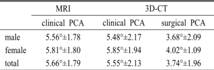
Table 1. Summary of data
MRI 3D-CT
clinical PCA clinical PCA surgical PCA male 5.56°±1.78 5.48°±2.17 3.68°±2.09 female 5.81°±1.80 5.85°±1.94 4.02°±1.09 total 5.66°±1.79 5.55°±2.13 3.74°±1.96 PCA: posterior condylar angle;
5.81(±1.80)도 이였다. 삼차원 전산화단층촬영의 경우 임 상적 대퇴 후상과간 각은 평균 5.55(±2.13)도 이였고, 남 자는 5.48(±2.17)도, 여자는 5.85(±1.94)도 이였으며. 수술 적 대퇴 후상과간 각은 평균 3.74(±1.96)도 이였고, 남자 는 3.68(±2.09)도, 여자는 4.02(±1.09)도 이였다(Table 1).
성별에 의한 차이는 자기공명영상 검사에서 0.25도 이였 고, 삼차원 전산화단층촬영에서는 임상적 및 수술적 대퇴 상과간 축에 대해 각각 0.37도, 0.34도 이였으나, 통계학적 인 의의는 없었다(p>0.05). 자기공명영상의 임상적 대퇴 후상과간 각이 삼차원 전산화단층촬영의 임상적 대퇴 후 상과간 각보다 0.11도 많았으나, 통계학적 의미는 없었으 며(p>0.05), 삼차원 전산화단층촬영에서의 임상적 및 수술 적 대퇴 후상과간 각의 차이는 1.81도 였으며, 이는 통계 학적으로 의의가 있었다(p<0.01).
고 찰
슬관절 전치환술을 시행할 때 염두해야 할 사항 중의 하나인 적절한 대퇴 삽입물의 회전 정렬은 슬개골 정렬과 경골 - 대퇴골간 굴곡 안정성10,15)에 영향을 주어 대퇴 삽입 물의 외회전이 적을 경우 슬개 - 대퇴 관절의 탈구나 아탈 구를 조장하게 되고, 슬개 삽입물과 경골 삽입물의 마모 와 해리 등을 유발하는 중요한 원인이 되고 있다2,14,16). 이 론적으로는 대퇴 상과간 축이 슬관절 회전 중심과 일치하 므로 대퇴 상과간 축을 슬관절 전치환술시 대퇴 삽입물 회전 정렬의 기준으로 사용하는 것이 타당하나1,3,8,11), 수술 시 내 - 외과를 덮고 있는 인대 및 지방 조직으로 인해 정 확한 내 - 외과의 위치를 잡는 것이 어렵기 때문에 대부분 의 시술자들이 대퇴 후과간 축을 이용하고 있다. 그러나 대퇴 상과간 축과 대퇴 후과간 축이 일치하지 않기 때문 에 정확한 대퇴 삽입물의 회전 정렬을 위해서는 대퇴 상 과간 축과 대퇴 후과간 축의 차이를 규명하는 것이 슬관
절 전치환술시 대퇴 삽입물을 정확한 위치에 고정하는데 필수적이라고 할 수 있다. 또한 우리나라에서는 이들 기 준 축에 관한 보고6,17)가 적어 한국인에서의 이들 차이를 규명할 필요가 있다. 대퇴 상과간 축과 대퇴 후과간 축이 이루는 각을 대퇴 후상과간 각이라고 하는데, 이의 측정 은 생체나 사체에서 실제 대퇴골을 이용하는 것이 타당하 나, 이는 우리나라의 현실을 감안할 때 그리 쉽지 않다.
이에 저자들은 자기공명영상 및 삼차원 전산화단층촬영 의 축성 단면에서 대퇴 상과간 축과 대퇴 후과간 축을 도 시하여 대퇴 후상과간 각을 측정하였다. 삼차원 전산화단 층 촬영은 자기공명영상이나, 일반 전산화단층촬영에서처 럼 하나의 축성 단면이 아닌, 대퇴골의 모양을 삼차원적 으로 재생해서 보여줌으로써 실제 생체 대퇴골의 모습을 그대로 재현할 수 있었다. 또한, 원위 대퇴골을 다각도로 접근하여 양측 상과 및 내과 홈이 뚜렷하게 보이는 영상 을 얻을 수 있어 실제 생체 대퇴골과 유사한 임상적 및 수 술적 대퇴 상과간 축과 대퇴 후과간 축을 도시할 수 있어 대퇴 후상과간 각, 즉 두 축의 외회전 정도를 알 수 있었 다. 저자들의 연구에서 대퇴 후상과간 각은 자기공명영상 에서 평균 5.66(±1.79)도, 삼차원 전산화단층촬영에서 임 상적 대퇴 후상과간 각은 5.55(±2.13)도, 수술적 대퇴 후 상과간 각은 3.74(±1.96)도로 측정되었다.
조 등6)은 자기공명영상을 이용하여 측정한 결과 평균 4.8 (±2.0)도으로 보고하였고, 연령 및 성별 비교 시 20대에서 성별에 따른 유의한 차이가 있다고 하였다. 이는 저자들 의 5.66(±1.79)도와 0.86도의 차이를 보이는데, 이는 연구 대상의 평균 연령이 조 등6)의 연구에서는 평균 31.2세로, 본 연구의 평균 51.8세와 차이가 있어 연구 결과에 어느 정도 영향을 끼쳤을 것으로 사료된다. Boisgard 등5)은 슬 관절염군 103례를 전산화단층촬영을 이용하여 측정한 대 퇴 후상과간 각을 평균 2.65도로 보고하였고, Yoshino 등18) 도 전산화단층촬영에서 임상적 대퇴 후상과간 각을 6.4(±
1.6)도, 수술적 대퇴 후상과간 각을 3.0(±1.6)도로 보고하 였다. Yoshioka 등19)은 대퇴골 실물을 통해 측정한 결과 남 녀별 각각 5.0(±1.8)도, 6.0(±2.4)도로 보고하였다. 또한, Berger 등4)이 보고한 것은 남녀 각각 3.0(±1.2)도, 0.3(±1.2) 도로, Matsuda 등13)은 평균 6.03도로 보고하는 등 저자에 따라 다양하게 보고되고 있다4,12). 이러한 차이를 보이는 것은 여러가지 이유가 있을 것으로 사료되나, 측정 대상 의 차이 즉, 한국인과 서양인의 골격 구조의 차이도 한 원
인이 될 수 있을 것으로 추정된다. 그러나 우리나라 사람 의 정상적인 대퇴골 원위부에 대한 국내의 연구 자료가 부족하여 객관적인 분석이 되지 않아 향후 이에 대한 연 구가 필요하리라 사료된다.
Matsuda 등13)은 대퇴 상과간 축이 대퇴 후과간 축에 대 하여 평균 6도 외회전되어 있어 대퇴 후과간 축도 슬관절 전치환술을 시행할 때 믿을만한 지표이지만, 이를 기준으 로 수술을 하면 대퇴부 삽입물을 상대적으로 내회전하여 고정할 수 있다고 하였다. 저자들의 연구 결과 역시 대부 분의 슬관절 전치환술에 사용되는 기준으로 대퇴 후과간 축에 대해 3도 외회전하여 정렬을 맞추는 경우 한국인에 서는 외회전이 부족하여 문제를 유발할 수 있으리라 생각 되었다. 그러나 외회전 정도는 본 연구에서 보듯 대퇴 상 과간 축을 내측과의 정점(most prominent point)을 기준으로 한 경우(임상적 대퇴 후상과간 각)와 내측과의 홈을 기준 으로 한 경우(수술적 대퇴 후상과간 각)에 따라서 그 결과 가 달라지므로4,18) 기준점 설정에 대한 통합적인 연구가 필요하다. 또한, 이번 연구에 있어서 실제 대퇴골 실물을 측정하지 못한 점이 한계점으로 제기될 수 있으나, 대퇴 골 실물을 사용한 경우 오히려 내 - 외과를 덮고 있는 인 대 및 지방 조직으로 인해 정확한 내 - 외과의 위치를 잡 는 것이 어려우므로, 이런 연부 조직을 제외하고, 원위 대 퇴골을 삼차원적으로 재구성함으로써 대퇴 후상과간 각 을 더욱 정확하게 측정할 수 있었다고 사료된다. 본 연구 에서는 퇴행성 관절염이 있는 환자와 정상인 사이에서의 대퇴 내과의 골 및 연골 소실로 인한 대퇴 후상과간 각의 차이를 직접 비교하지 않아 이에 대하여는 더 많은 연구 가 필요할 것으로 사료되었다.
결 론
단층 영상인 자기공명영상과 입체 영상인 삼차원 전산화 단층촬영으로 측정한 임상적 대퇴 후상과간 각은 차이가 없었다. 자기공명영상 검사를 이용하여 측정한 임상적 대 퇴 상과간 축은 평균 5.66(±1.79)도 대퇴 후과간 축에 대해 외회전되어 있었다. 삼차원 전산화단층촬영을 이용한 경우 임상적 대퇴 상과간 축으로는 5.55(±2.13)도, 수술적 대퇴 상과간 축으로는 3.74(±1.96)도 외회전되어 있어 슬관절 전 치환술시 슬관절 굴곡 상태에서 원위 대퇴부의 적절한 회 전 정렬을 잡기 위해서 사용되는 일반적인 기준으로 대퇴
후과간 축에 대해 3도 외회전하여 정렬을 맞추는 경우 한 국인에서는 외회전이 부족할 수 있다고 사료되었다.
REFERENCES
1. Akagi M, Yamashita E, Nakagawa T, Asano T and Na- kamura T: Relationship between frontal knee alignment and reference axes in the distal femur. Clin Orthop, 388:
147-156, 2001.
2. Anouchi YS, Whiteside LA, Kaiser AD and Milliano MT:
The effects of axial rotational alignment of the femoral com- ponent on knee stability and patellar tracking in total knee arthroplasty demonstrated on autopsy specimens. Clin Orthop, 287:170-177, 1993.
3. Arima J, Whiteside LA, McCarthy DS and White SE:
Femoral rotational alignment, based on the anteroposterior axis, in total knee arthroplasty in a valgus knee. J Bone Joint Surg, 77A:1331-1334, 1995.
4. Berger RA, Rubash HE, Seel MJ, Thompson WH and Crossett LS: Determining the rotational alignment of the femoral component in total knee arthroplasty using the epicondylar axis. Clin Orthop, 286:40-47, 1993.
5. Boisgard S, et al: Computed tomographic study of the posterior condylar arthritic knees: Its use in the rotational positioning of the implant of total knee prostheses. Surg Radiol Anat, 25(3-4):330-334, 2003.
6. Cho WS, Park SS, Kim JH, Kim DH and Kim MY: The discrepancy between epicondylar and posterior condylar axis of femur in total knee arthroplasty. J Korean Knee Society, 11:8-12, 1999.
7. Churchill DL, Incavo SJ, Johnson CC and Beynnon BD:
The transepicondylar axis approximates the optimal flexion axis of the knee. Clin Orthop, 356:111-118, 1998.
8. Griffin FM, Insall JN and Scuderi GR: The posterior condylar angle in osteoarthritic knees. J Arthroplasty, 13:812-815, 1998.
9. Hungerford DS and Kenna RV: Preliminary experience with a total knee prosthesis with porous coating used without cement. Clin Orthop, 176:95-107, 1983.
10. Insall JN: Technique of total knee replacement. Instr Course Lect, 30:324-329, 1981.
= Abstract =
Measurement of the Posterior Condylar Angle in Koreans
- Comparison between Three Dimensional Computed Tomography Study and Magnetic Resonance Imaging Study -
Young Joon Choi, M.D., Jae Kwang Hwang, M.D., Ki Won Lee, M.D., Ju Sik Jeon, M.D., and Ji Ho Choi, M.D.
Department of Orthopedic Surgery, Gangneung Asan Hospital, College of Medicine Ulsan University, Gangneung, Korea
Purpose: This study is to measure the posterior condylar angle (the angle between the femoral epicondylar axis and the femoral posterior condylar axis) which is commonly used for determining the degree of femoral component rotation during total knee replacement with magnetic resonance imaging (MRI) and three dimensional computed tomography (3D CT) and to assess the difference of this angle in Koreans.
Materials and Methods: We examined the 257 knee MRIs and 118 knee 3D CTs. And we measured the clinical posterior condylar angle in MRIs, and the clinical and surgical posterior condylar angle in 3D CTs.
Results: The clinical posterior condylar angle on MRI was male, 5.56° and female, 5.81° (mean, 5.66°). The clinical posterior condylar angle was male, 5.48° and female, 5.85° (mean, 5.55°), and the surgical posterior condylar angle was male, 3.68° and female, 4.02° (mean 3.74°) on 3D CT. There was no statistical difference in clinical posterior condylar angle between MRI and 3D CT (p>0.05) and between male and female(p>0.05).
Conclusion: There was no difference in clinical posterior condylar angle between MRI and 3D CT. We suggest that 3° external rotation of femoral component from posterior condylar axis may not be enough in Koreans during total knee replacement.
Key Words: Femur, Magnetic resonance imaging, Three dimensional computed tomography, Posterior condylar angle 11. Jerosch J, Peuker E, Philipps B and Filler T: Interindi-
vidual reproducibility in perioperative rotational alignment of femoral components in knee prosthetic surgery using the transepicondylar axis. Knee Surg Sports Traumatol Arthrosc, 10:194-197, 2002.
12. Laskin RS and Rieger MA: The surgical technique for performing a total knee replacement arthroplasty. Orthop Clin North Am, 20:31-48, 1989.
13. Matsuda S, Matsuda H, Miyagi T, Sasaki K, Iwamato Y and Miura H: Femoral condyle geometry in the normal and varus knee. Clin Orthop, 349:183-189, 1998.
14. Moreland JR: Mechanisms of failure in total knee arthro- plasty. Clin Orthop, 226:49-64, 1988.
15. Poilvache PL, Insall JN, Scuderi GR and Font-Rodriquez
ED: Rotational landmarks and sizing of the distal femur in total knee arthroplasty. Clin Orthop, 331:35-46, 1996.
16. Ranawat CS: The patellofemoral joint in total condylar knee arthroplasty. Clin Orthop, 205:93-99, 1986.
17. Sohn SW and Jung MH: Measurement of the axial rota- tional axis of distal femur using different landmarks. J Korean Knee Soc, 11:129-133, 1999.
18. Yoshino N, Takai S, Ohtsuki Y and Hirasawa Y: Com- puted tomography measurement of the surgical and clinical transepicondylar axis of the distal femur in osteoarthritic knees. J Arthroplasty, 16:493-497, 2001.
19. Yoshioka Y, Siu D and Cooke DV: The anatomy and fun- ctional axes of the femur. J Bone Joint Surg 69A:873-880, 1987.