Korean J. Mater. Res.
Vol. 29, No. 12 (2019)
757
Stacked High Voltage Al Electrolytic Capacitors Using Zr-Al-O Composite Oxide
Kaiqiang Zhang
1and Sang-Shik Park
2†1Department of Materials Science and Engineering, Research Institute of Advanced Materials, Seoul National University, Seoul 08826, Republic of Korea
2School of Nano Materials Engineering, Kyungpook National University, Gyeongbuk 37224, Republic of Korea
(Received October 25, 2019 : Revised November 27, 2019 : Accepted November 27, 2019)
Abstract
A stacked high-voltage (900 V) Al electrolytic capacitor made with ZrO2 coated anode foils, which has not been studied so far, is realized and the effects of Zr-Al-O composite layer on the electric properties are discussed. Etched Al foils coated with ZrO2 sol are anodized in 2-methyl-1,3-propanediol (MPD)-boric acid electrolyte. The anodized Al foils are assembled with stacked structure to prepare the capacitor. The capacitance and dissipation factor of the capacitor with ZrO2 coated anode foils increase by 41 % and decrease by 50 %, respectively, in comparison with those of Al anode foils. Zr-Al- O composite dielectric layer is formed between separate crystalline ZrO2 with high dielectric constant and amorphous Al2O3 with high ionic resistivity. This work suggests that the formation of a composite layer by coating valve metal oxide on etched Al foil surface and anodizing it in MPD-boric acid electrolyte is a promising approach for high voltage and volume efficiency of capacitors.Key words
ZrO2, anodization, composite layer, stacked structure, high-voltage capacitor.1. Introduction
Capacitor is an electric device with higher power and shorter charging time compare to battery and extensively utilized in many circuits requiring high power. Al electrolytic capacitors as key passive components in electric devices have many extraordinary properties such as particular self-healing as well as a remarkable life time. The structure of conventional Al electrolytic capacitor consists of anode and cathode foils, and electrolytic paper immersed by electrolyte with wide temperature range and ionic conductivity. The dielectric layer, Al
2O
3in Al electrolytic capacitor has been formed by anodizing etched Al foils in electrolyte under certain formation voltage. They are usually operated at moderate voltage condition below 500 V. A volume efficient high-voltage Al electrolytic capacitor (voltage of over 700 V may be regarded as high-voltage) will be extensively used in the field of high-power device. Thus, many efforts have been done on the increase of volume efficiency, and certain progresses have been realized.
1-5)The capacitance of
capacitors can be expressed as follows.
C = Ɛ
0Ɛ
rS/d (1)
Where Ɛ
0is the dielectric constant of vacuum, Ɛ
ris the relative dielectric constant of the dielectric material, S is the effective area of the electrode, and d is the thickness of the dielectric layer. In addition to broadening the effective surface area of Al foil to enhance volume efficiency, which is the widely used approach in nowadays capacitor industry, the C can also be enhanced by decreasing the d and increasing the Ɛ
r. However, the approach for decreasing thickness of dielectrics is not appropriate because of accompanying low withstanding voltage. The thickness of dielectrics formed by anodization is approximately 1 nm V
−1.
6)Moreover, there is a negative empirical trend that a dielectric layer with high Ɛ
rhas lower ionic resistivity and higher dissipation factor. Thus, even if the dielectric layer with lower Ɛ
ris replaced by others with higher Ɛ
r, the dissipation factor and thickness, d will correspondingly increase failing to effectively enhance
†Corresponding author
E-Mail : [email protected] (S. Park, Kyungpook Nat’l Univ.)
©Materials Research Society of Korea, All rights reserved.
This is an Open-Access article distributed under the terms of the Creative Commons Attribution Non-Commercial License (http://creative- commons.org/licenses/by-nc/3.0) which permits unrestricted non-commercial use, distribution, and reproduction in any medium, provided the original work is properly cited.
758 Kaiqiang Zhang and Sang-Shik Park
the C. Therefore, the composite oxide composed of Al
2O
3with higher ionic resistivity and valve metal oxide with higher Ɛ
rshould be a promising approach for increasing volume efficiency of the capacitor. Coating valve metal oxides such as SiO
2, TiO
2, Nb
2O
5, and BaTiO
3on etched Al foils is extensively studied in lab scale for increasing the specific capacitance (C) and many promising results have been achieved.
7-11)Further study on C enhancement is needed for realization of volume efficient capacitor.
In order to explore the micro-structure of the dielectric layer coated with valve metal oxide, ZrO
2was chosen for the formation of Zr-Al-O composite dielectric layer, because the permittivity of ZrO
2considerably exceeds that of Al
2O
3(8 ~ 9) and the leakage current in ZrO
2films is commonly lower than in another high-k oxide candidate Ta
2O
5.
12)The composite oxide layer was formed by anodizing ZrO
2coated Al foils in MPD-boric acid electrolyte. The MPD can effectively inhibit the micro- arcs caused by O
2evolution process during high voltage anodization. Micro-arcs result in local breakdown in the dielectric layer, which decrease the specific capacitance due to the decrease in effective area of the electrode.
More about the severe micro-arcs in anodization at high voltage has been specifically discussed in our previous work.
13)Capacitors with stacked structure show more volume efficiency than traditional wound type capacitor.
After anodization of ZrO
2coated Al foils, we prepared stacked high-voltage Al electrolytic capacitor (900 V) which has not been explored so far, and investigated electrical properties of stacked capacitor.
2. Experimental Procedure 2.1 Preparation of Anode Foil
The flow chart for the formation of anodic foils with Zr-Al-O composite dielectric layer is shown in Fig. 1. The ZrO
2sol (0.8 mol L
−1) was prepared by mixing zirconium butoxide (Zr(OC
4H
9)
4; 80 wt% in 1-butanol; Sigma-Aldrich;
USA), 2-methoxyethanol (CH
3OCH
2CH
2OH; anhydrous;
99.8 %; Sigma-Aldrich; USA), acetic acid (CH
3COOH;
99.7 %; Daejung Chemicals & Metals; Korea). The molar ratio of the acetic acid to Zr was 6. Following stirring for 1 h by a magnetic stirrer, nitric acid (HNO
3; 60-62 %;
Daejung Chemicals & Metals; Korea) was added, and the sol was aged for 3 days. A commercial tunnel-etched aluminum foil for high voltage usage with high purity (> 99.99 %) was used as specimen. Al foils of 6 by 8 cm (thickness: ~125 µm; hole density: ~2.0 × 10
7cm
−2; hole diameter: 1-2 µm; length: 40-50 µm) were coated with the previously prepared ZrO
2sol by vacuum infiltration.
Four-times coating was conducted to obtain the largest capacitance of the composite dielectric layer in accordance with our previous results.
2)The drying and annealing
temperature for the ZrO
2sol were 100 and 500
oC, respectively.
The anodic dielectric layer was formed by anodizing ZrO
2coated Al foils at 900 V in MPD-boric acid electrolyte until the current flowing through the sample was 0.1 A cm
−2. MPD:boric acid solutions (100 g/L) was prepared with volume % ratio of 3:10. The temperature of the MPD-boric acid electrolyte was kept at 90
oC during anodization. We have found that the annealing process effectively contributes to increasing the Ɛ
r. Moreover, the increase in anodization cycle contributes to reducing the dissipation factor of the dielectrics, but diminishes the specific capacitance. Thus, two-times anodization here was chosen as optimized condition.
2.2 Characterization
The cross-sectional structures and micro-structures of the ZrO
2coated and anodized samples were characterized by field emission-transmission electron microscopy (FE- TEM, titan G2 ChemiSTEM Cs probe, FEI) performing at 200 kV. The samples were thinned with a focused ion beam (FIB, versa 3D LoVac, FEI) for the proper thickness.
The elemental distributions of the ZrO
2-coated sample
were examined by TEM coupled with energy-dispersive
X-ray spectroscopy (EDS). The crystalline structures of
the dielectric layer on the etched Al foil before and after
anodization were analyzed using X-ray diffraction (XRD,
X’Pert Pro MRD, PANalytical). The withstanding voltage
of specimens was examined by a source meter (2410,
Keithley) in a boric acid solution (10 wt%) at 85
oC. The
measurement of the electrochemical impedance spectroscope
(EIS) and cyclic voltammetry (CV) for capacitors with
Fig. 1. The flow chart of the preparation for ZrO2-coated anode.ZrO
2coated and non-coated anode foils were determined by a potentiostat(VersaSTAT 3, Princeton Applied Research) with a triple-electrode system (anodized Al foils as anode, a Pt foil as cathode, and Ag/AgCl reference electrode) monitored by a computer. The capacitances and dissipation factors were determined with an impedance/gain phase analyzer(4194A, Hewlett-Packard). All electrochemical measurements were conducted under ambient conditions at around 20
oC.
3. Results and Discussion
In order to clarify the structure and composition of the coating and anodized layer, the samples were examined by TEM and the corresponding morphology image and elemental depth profile are shown in Fig. 2(a) and (b).
Etch pits were formed vertically on Al foil surface.
Specimens were milled by FIB to measure the cross-
section of etch pits. Fig. 2(a) shows TEM images of the
cross-sections and electron diffraction patterns of the Zr-
Al-O composite and Al
2O
3layer. Two inset diffraction
patterns in upper part are those of Al
2O
3layer and the
diffraction pattern in lower part is that of Zr-Al-O composite
layer. The oxide layer consisted of an inner Zr-Al-O
composite layer with relatively high crystallinity and a
middle Al
2O
3layer with relatively low crystallinity similar
to previous report.
14)The total thickness of the oxide
layer was approximately 810~920 nm. In considering that
the thickness of ZrO
2coating layer was approximately
150 nm, the thickness of Al
2O
3layer formed by anodization
was thinner than expected value. The ratio of the oxide
thickness to the oxide formation voltage, K, is reported
Fig. 2. (a) TEM image of the cross section of the formed dielectric layer, (b) EDS result of elemental depth profile of the dielectric layer, (c) high resolution transmission electron microscopy of the Zr-Al-O composite layer, (d) XRD results of the ZrO2-coated Al foils before and after anodization.760 Kaiqiang Zhang and Sang-Shik Park
values of anodic oxide films of 0.8~1.3 nm·V
−1.
15)The EDS depth profile of Fig. 2(b) shows the composition from outside to inside in the blue line of Fig. 2(a). Multi- layer structure: outer Al substrate; middle: Al
2O
3layer;
inner Zr-Al-O composite layer is shown clearly.
The growth of Al
2O
3layer is mainly by the migration of O
2−towards Al substrate under the driving force given by the electric field. The outward transport of O
2−ions comes from dissociation of electrolyte in etch pit. The crystallinity of Al
2O
3layer decreases with position from electrolyte side to Al substrate side as shown in selected area electron diffraction patterns. After anodization, the ZrO
2coating layer is totally transformed to Zr-Al-O composite layer as shown in the EDS result Fig. 2(b).
The Zr species largely transports towards inner side in the term of Zr
4+and ZrO
2+during anodization.
16)The micro- structure of Zr-Al-O composite layer is characterized by high resolution transmission electron micrograph (HRTEM) shown in Fig. 2(c). The Zr-Al-O composite layer exists in the form of a combination between crystalline ZrO
2with higher dielectric constant and amorphous Al
2O
3with higher ionic resistivity. The crystallinity of each region was identified by the fast Fourier transform (FFT) images like previous report.
14)The spacing of the lattice obtained from the crystalline region is 0.297 nm, which matches the spacing of (011) plane of tetragonal ZrO
2. The crystalline ZrO
2region must contain slight Al species due to the limited solubility (1 at% or less) of Al species to crystalline ZrO
2.
17,18)The limited solubility should be the reason for the separation of crystalline ZrO
2. Thus, the amorphous phase must mainly contain Al
2O
3species.
This sort of combined form successfully contributed to the C
penhancement from the viewpoints of d and Ɛ
raccording to Eq. (1). ZrO
2annealed at 500
oC is tetragonal phase according to the XRD pattern of Fig. 2(d). However, monoclinic ZrO
2is observed as a new phase in the XRD
pattern of anodized sample. We assume the change in ZrO
2phase from only tetragonal to the coexistence of tetragonal and monoclinic is due to the inclusion of Al species.
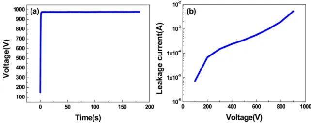
The withstanding voltages and the leakage currents of the specimens anodized at 900 V are shown in Fig. 3.
The withstanding voltage of the specimens anodized at 900 V is approximately 977 V [Fig. 3(a)]. All anodized ZrO
2-coated specimens could withstand the corresponding voltage. The leakage current in Fig. 3(b) is similar to that of other composite oxide dielectrics such as TiO
2and BaTiO
3.
7,19)The leakage current cannot be totally eliminated.
The causes of leakage current are distorted polarization of dielectric, Resolution and formation of dielectric and breakdown of dielectric.
After anodization and annealing, anode foils are assembled with cathode foils and manila papers for preparation of high voltage capacitor shown in Fig. 4. The stacked type capacitors show remarkably low ESR characteristics and high ripple current capability compared to cylindrical Al electrolytic capacitor and also allows for increased capacitance per unit area. This type capacitor provides up
Fig. 3. (a) Withstanding voltage and (b) leakage current of ZrO2-coated Al foils anodized at 900 V.
Fig. 4. Schematic representation showing the structure and appearance of high-voltage Al electrolytic capacitor element.
to 1.3 times capacitance per unit area as compared to the conventional type.
20)Also stacked type capacitors obtained by assembling the anode and cathode foils have applications such as high frequency and a lower impedance.
21)Different from conventional cylindrical Al electrolytic capacitor, the capacitor is assembled with anode foils, manila papers, and cathode foils with 5 layer-stacked structure, which can be specifically described as that an anodized foil is between two cathode foils and manila papers separate every two electrodes. Finally, the stacked structure is held tightly together. Two Al strips (1.5 by 3 cm) are then attached to both anode and cathode foils, respectively.
Prior to insertion into a pouch, the stacked capacitor element (6 by 8 cm) is immersed in an ammonium penta-borate electrolyte of 80 g L
−1. The entire assembling process is operated in a room with an ambient temperature of 20
oC and humidity of 50 %. Manufacturing capacitor samples showed the capacitance above 110 µF at 120 Hz.
The assembled capacitor is then left for 72 h in order to ensure that every component is sufficiently soaked with ammonium penta-borate electrolyte. Then, the measurements of charge storage performances are conducted and the CVs are swept in the region of -2 V to 2 V to study the
surface properties of electrode. The CV curves are obtained by applying an excitation signal scanning with a triangular waveform on the capacitors with and without ZrO
2coated anode foils to stimulate a current-responding signal. The CVs of the capacitors with and without ZrO
2coated anode foils at sweep rates of 1, 5, and 10 V/s are shown in Fig. 5(a) and (b), respectively. The current linearly increases with the sweep rate which suggests a good rate capability at high sweep rate. There are no redox reaction peaks indicating that charging and discharging are reversible at the dielectric layer. The near rectangular CVs obtained from the capacitor with ZrO
2coated anode foils indicate better capacitive behavior than that without ZrO
2coated anode foils even at such high scan rate.
Moreover, the CVs obtained from the capacitor with ZrO
2coated anode foils exhibit more ideal ionic resistivity than that from non-coated anode foils, which associates with better dielectric property of the amorphous Al
2O
3in Zr-Al-O composite layer. The same result is also shown in the corresponding EIS measurement results in Fig.
5(c). The curves are divided into three regions: a straight
line with slope of -1 in middle frequency and horizontal
lines in the lower and higher frequency regions. Zr-Al-O
Fig. 5. (a) Current-voltage curves of the capacitor with ZrO2-coated anode foils, (b) with non-coated anode foils, (c) impedance-frequency curves of the capacitors with non-coated and ZrO2-coated anode foils, (d) responsive current-time curves for the excited signal on the capacitor with ZrO2-coated anode foils.762 Kaiqiang Zhang and Sang-Shik Park
composite layer significantly increases the impedance of capacitor in lower frequency region. The impedance in low frequency region depends mainly on both dielectric layer and electrolyte. As the same ammonium penta-borate electrolyte is used in assembling the capacitor cells, the enhancement in impedance is mostly depending on the Zr-Al-O composite layer. The capacitances of the capacitor with ZrO
2coated anode foils are determined by the current- time (CT) curves shown in Fig. 5(d) through integration.
The quantities of electric charge are 0.004316, 0.000881, and 0.000580 C at sweep rates of 1, 5, and 10 V s
−1, respectively. Therefore, the capacitance should decrease with increasing sweep rate according to C = Q/V since there is insufficient time for the ions transport in the energy storage process.
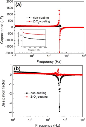
Fig. 6(a) and (b) show the capacitances and dissipation factors of the capacitors with ZrO
2coated and non-coated anode foils. The specific capacitances and dissipation factors at 120 Hz are 0.36 µF cm
−2and 0.334 for the capacitor with non-coated anode foils, 0.52 µF cm
−2and 0.167 for that with ZrO
2coated anode foils. Almost 41 % increase in capacitance and 50 % decrease in dissipation
factor are achieved by coating ZrO
2on the surface of etched Al foils, which indicate that forming Zr-Al-O composite layer with the special micro-structure of separated crystalline ZrO
2with high dielectric constant and amorphous Al
2O
3with high ionic resistivity is an effective approach to increase the C
pand decrease the dissipation factor.
The dielectric constant of Al
2O
3and ZrO
2is well known as 9 and 25 respectively. An inclusion of ZrO
2in Al
2O
3dielectrics, which is used in Al electrolytic capacitor now, must lead to increase of capacitance. An increase in capacitance by coating ZrO
2on the surface of etched Al foils and stacked structure shows great promise of highly volume efficient capacitor.
4. Conclusions
Zr-Al-O composite dielectric layer for stacked high voltage (900 V) capacitor is realized by anodizing ZrO
2coated Al-etching foils in MPD-boric acid electrolyte at 90
oC. A triple-layer structure of inner Zr-Al-O composite layer, middle Al
2O
3layer, and outer etched Al substrate is formed after anodization. The ZrO
2coated layer is totally transformed to Zr-Al-O composite layer with separated crystalline ZrO
2with high dielectric constant and amorphous Al
2O
3with high ionic resistivity. The capacitances and dissipation factors at 120 Hz are 0.36 µF cm
−2and 0.334, 0.52 µF cm
−2and 0.167 for high-voltage stacked Al electrolytic capacitors without and with ZrO
2coated anode foils, respectively. Almost increase of 41 % in capacitance and decrease of 50 % in dissipation factor are achieved by forming Zr-Al-O composite dielectric layer. The capacitors with ZrO
2-coated anode foils are a kind of promising candidate in the preparation of high voltage Al electrolytic capacitors with high volume efficiency.
Acknowledgement
This research was supported by Basic Science Research Program through the National Research Foundation of Korea (NRF) funded by the Ministry of Education (2017033541).
References
1. C. Ban, Y. He, S. Xin and J. Du, Trans. Nonferrous Met.
Soc. China, 23, 1039 (2013).
2. F. Chen and S. S. Park, ECS J. Solid State Sci. Technol., 4, 293 (2015).
3. J. K. Chang, C. M. Liao, C. H. Chen and W. T. Tsai, J.
Power Sources, 138, 301 (2004).
4. J. Ren and Y. Zuo, Appl. Surf. Sci., 261, 193 (2012).
5. S. Stojadinovic, I. Belca, M. Tadic, B. Kasalica, Z. Nedic and L. Zekovic, J. Electroanal. Chem., 619, 125 (2008).
Fig. 6. (a) Capacitances and (b) dissipation factors of the capacitors with non-coated and ZrO2-coated anode foils.
6. T. Kudo and R. S. Alwitt, Electrochim. Acta, 23, 341 (1978).
7. L. Xiang and S. S. Park, Appl. Surf. Sci., 388, 245 (2016).
8. S. S. Park and B. T. Lee, J. Electroceramics, 13, 111 (2004).
9. S. Koyama, Y. Aoki, S. Nagata and H. Jabazali, J. Solid State Electrochem., 15, 2221 (2011).
10. Z. S. Feng, J. J. Chen, R. Zhang and N. Zhao, Ceram.
Int., 38, 3057 (2012).
11. X. Du and Y. Xu, Thin Solid Films, 516, 8436 (2008).
12. K. Kukli, M. Ritala, T. Uustare, J. Aarik, K. Forsgren, T.
Sajavaara, M. Leskelä and A. Hårsta, Thin Solid Films, 410, 53 (2002).
13. K. Zhang and S. S. Park, Surf. Coat. Technol., 310, 143 (2017).
14. K. Zhang and S. S. Park, Appl. Surf. Sci., 477, 44 (2019).
15. T. Kudo and R. S. Alwitt, Electrochim. Acta, 23, 341 (1978).
16. K. Watanabe, M. Sakairi, H. Takahashi, S. Hirai and S.
Yamaguchi, J. Electroanal. Chem., 473, 250 (1999).
17. D. A. Jerebtsov, G. G. Mikhailov and S. V. Sverdina, Ceram. Int., 26,821 (2000).
18. P. Doerner, L. J. Gauckler, H. Krieg, H. L. Lukas. G.
Petzow and J. Weiss, CALPHAD, 3, 241 (1979).
19. L. Xiang and S. S. Park, Thin Solid Films, 623, 19 (2017).
20. G. Takano, M. Shimizu, K. Nakaaki, M. Weaver and M.
Kudo, Conference Record of the 2004 IEEE Industry Applications Conference, 2004. 39th IAS Annual Meeting, 4, 2555 (2004).
21. N Derrick and J Zeigler, US patent 3,806,769 (1974).
< 저자소개 >
Kaiqiang Zhang
서울대학교 재료공학과 박사과정 학생 박상식
경북대학교 나노소재공학부 교수