AJCPP 2008 March 6-8, 2008, Gyeongju, Korea
Measurement of the Film Cooling Effectiveness on a Flat Plate using Pressure Sensitive Paint
S. D. Park and K. S. Lee
Graduate student, School of Aerospace and Mechanical Engineering, Korea Aerospace University J. S. Kwak*
Corresponding author, School of Aerospace and Mechanical Engineering, Korea Aerospace University 200-1 Hwajoen-Dong, Deogyang-Gu, Goyang-City, 417-791, Korea
[email protected] B. J. Cha
KHP Development Division, Korea Aerospace Research Institute 45 Eoeun-Dong, Yuseong-Gu, Dajeon, Korea
Keywords: film cooling, turbine blade cooling, pressure sensitive paint, film cooling effectiveness
Abstract
Film cooling effectiveness on a flat plate was measured with pressure sensitive paint. The pressure sensitive paint (PSP) changes the intensity of its emissive light with pressure and the characteristic was used in film cooling effectiveness measurement. The film coolants were air and nitrogen, and by comparing the intensity of PSP coated surface with each coolant, the film cooling effectiveness was calculated. Three blowing ratio of 0.5, 1, and 2 were tested with two mainstream turbulence intensities. Results clearly showed the effect of blowing ratio and mainstream turbulence intensity. As the blowing ratio increases, the film cooling effectiveness was decreased near the film cooling holes. However, the film cooling effectiveness far downstream from the injection hole was higher for higher blowing ratio. As the mainstream turbulence intensity increased, the film cooling effectiveness was decreased at far downstream from the injection hole.
1. Introduction
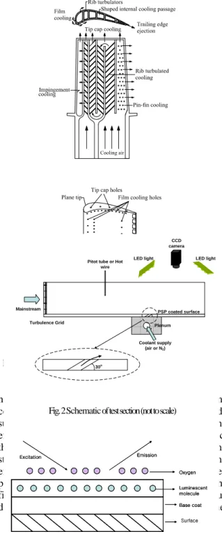
The turbine inlet temperature of modern gas turbine engines has been increased to achieve higher thermal efficiency. However, the increased inlet temperature can result in material failure of the turbine system due to the higher heat load and induced thermal stress. The engine cooling system must be designed to ensure that the level of thermal stress induced by temperature gradient is compatible with the maximum allowable stress of turbine components. Various cooling techniques are applied to the gas turbine blade. Figure 1 shows the cooling technique used in the modern gas turbine blade. In the gas turbine blades, rib turbulated cooling, pin-fin cooling, and impingement cooling are applied in blade’s internal coolant passage in order to remove heat from the blade inside. On the blade external surface, film-cooling method is employed in order to protect the blade surface from the hot combustion gas. In a film cooled component, relatively cooler air is injected through several discrete
holes which form a protective film between turbine components and hot combustion gas. On the blade surface, the accurate information of film cooling effectiveness should be evaluated in order to predict the exact temperature distribution in the blade. Many studies on the measurement of the film cooling effectiveness on gas turbine blade have been performed.
1Recently, Kwak and Han
2)studied the film cooling effectiveness on the blade tip using hue detection based transient liquid crystal technique.
Fig. 1 Cooling techniques used in a modern gas turbine blade
Turbulence Grid
Pitot tube or Hot wire
PSP coated surface
Coolant supply (air or N2)
Plenum CCD camera LED light LED light
Mainstream
30o
Fig. 2 Schematic of test section (not to scale)
Base coat Oxygen
Luminescent molecule
Excitation Emission
Base coat Oxygen
Luminescent molecule
Excitation Emission
Base coat Oxygen
Luminescent molecule
Excitation Emission
AJCPP 2008 March 6-8, 2008, Gyeongju, Korea
They used three tip clearances (1.0%, 1.5% and 2.0%
of blade span) along with three blowing ratio (0.5, 1.0 and 2.0). Ahn and Han
3)measured the film cooling effectiveness using pressure sensitive paint technique on turbine blade tip. They used same test section and flow loop used by Kwak and Han
2).
Pressure sensitive paint technique used for measuring film cooling effectiveness is mass transfer analogy and no heating of the test section or coolant is required. Also, the tests are performed under steady flow conditions. Thus, conduction errors at the test section and initial temperature errors, which causes problems in the film cooling effectiveness measurement by the liquid crystal technique, can be avoid.
Several papers are available in literature, which discuss the application of pressure sensitive paint technique. Morris,5) Mclaclan and Bell6) applied PSP to aerodynamics. Zhang et al7), 8) and Jaiswal9) studies the film cooling effectiveness on the flat plate using PSP technique. They also applied PSP technique to measure the film cooling effectiveness distributions on the turbine nozzle end-wall region.
In this study, PSP was used to measure the effect of turbulence intensity and blowing ratio on the film cooling effectiveness on a flat plate. Two turbulence intensities (0.5% and 7.2%) and three blowing ratio (0.5, 1.0, and 2.0) were tested.
2. Experimental Setup
A schematic of the test section is shown in Figure 2.
The test section consists of turbulence generating grid, a flow meter for coolant, 14bit CCD-camera, LED lightings. A turbulence generating grid with a porosity of 50% was placed 1500mm upstream from the injection hole and the turbulence intensity measured by hot-wire anemometry (KANOMAX). The turbulence intensity with and without the grid was 7.2% and 0.5%, respectively. The mainstream velocity was fixed as 20m/s. 14bit CCD camera measured the emitting light of the PSP and the captured images were stored in computer. Six film cooling holes of diameter of 5mm were fabricated with 30 degree angle with respect to the measurement surface. Tests were performed for two turbulence intensities of 0.5% and 7.2%. for each turbulence intensity, three blowing ratios of 0.5, 1.0, and 2.0 were tested. The blowing ratio was defined as (1).
c
u
cM u
ρ ρ
∞ ∞= (1)
In Eq.(1), M is blowing ratio, ρ and ρ
c ∞are the densities of coolant air and mainstream, respectively,
u
c and u∞ are the velocities coolant air and mainstream, respectively.
3. Film cooling Effectiveness Measurement Theory
3.1. Pressure sensitive paint
Pressure sensitive paint is a photo-luminescent material that emits light with intensity proportional to the surrounding partial pressure of oxygen.
4)Figure 3 shows a schematic of a luminescent pressure sensitive paint layer emitting radiation under excitation by an incident light. Pressure sensitive paint is divide into base coat layer and mixture layer of polymer bind with luminophore molecule. The polymer binder for PSP is oxygen permeable, which allows oxygen molecules to interact with the molecules in the binder. The interaction between luminophore molecule and oxygen molecule is called as oxygen quenching. The main photophysical process in PSP is oxygen quenching, i.e. decrease of the luminescent intensity as the partial pressure of oxygen or pressure increase.
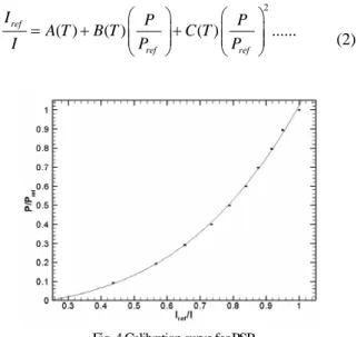
Hence, the luminescent intensity is a decreasing function of air pressure. The relationship between the luminescent intensity and pressure(oxygen concentration) can be Expressed as Eq.(2)
2
( ) ( ) ( ) ...
ref
ref ref
I P P
A T B T C T
I P P
⎛ ⎞ ⎛ ⎞
= + ⎜ ⎜ ⎟ ⎟ + ⎜ ⎜ ⎟ ⎟
⎝ ⎠ ⎝ ⎠ (2)
In Eq. (2), I
refand P
refare the luminescent intensity and air pressure at a reference condition, respectively. P and I are the air pressure and luminescent intensity at the pressure. Coefficients A, B, and C depend on the type of PSP and should be determined by calibration.
3.2 PSP Measurement Theory
PSP is a photo-luminescence material that changes emitting light intensity inversely proportional to the surrounding partial pressure of oxygen. In the film cooling measurement, air and nitrogen are used as coolant and emitting light intensities of each case are compared in order to calculate the film cooling effectiveness. For each case, the partial pressure of oxygen can be calculated by Eqs. (3) and (4).
Fig. 4 Calibration curve for PSP
54
AJCPP 2008 March 6-8, 2008, Gyeongju, Korea
Fig. 5 Distribution of film cooling effectiveness ( TI=0.5% ) ((
2) )
ref blk
O air air blk
I I
func P
I I
− =
− (3)
((
2) )
ref blk
O mix
mix blk
I I
func P
I I
− =
− (4)
Where Iref , Iair , Iblk and Imix are reference image, air image, black image,,,, and mixture (air/nitrogen) image, respectively. The test conditions for each image are listed in Table 1. The reference image is taken without any mainstream flow but with coated surface illuminated. The air image is taken with the mainstream flow, air as coolant, and illuminations.
, Iblk and Imix are reference image, air image, black image,,,, and mixture (air/nitrogen) image, respectively. The test conditions for each image are listed in Table 1. The reference image is taken without any mainstream flow but with coated surface illuminated. The air image is taken with the mainstream flow, air as coolant, and illuminations.
are reference image, air image, black image,,,, and mixture (air/nitrogen) image, respectively. The test conditions for each image are listed in Table 1. The reference image is taken without any mainstream flow but with coated surface illuminated. The air image is taken with the mainstream flow, air as coolant, and illuminations.
The black image is taken without any flow or illumination in order to consider the noise of camera itself. The mixture image is taken with the mainstream flow, nitrogen as coolant, and illuminations.
Table 1. Images required for film cooling measurement by PSP
Images Light wind
tunnel coolant
black image OFF OFF OFF
reference image ON OFF OFF
air image ON ON air
air/nitrogen image ON ON nitrogen
( P
O2)
airand
( P
O2)
mixwere the oxygen partial pressures which were obtained form the result of calibration in Figure 4. The film cooling effectiveness can be calculated by comparing the oxygen partial pressure of two coolant cases.
For the case of nitrogen as a coolant, oxygen partial pressure is 0 and the film cooling effectiveness is 1 if the surface is fully covered by the coolant (nitrogen).
In other case, if the oxygen partial pressure is same for two coolant cases, there is not effect of the injected nitrogen and the film cooling effectiveness becomes 0.
Hence, the film cooling effectiveness can be expression as a ratio of oxygen concentrations measured by pressure sensitive paint as shown in Eq.
(5).
2 2
2
( ) ( )
( )
air mix
air
O O O air O mix
O O air
C C P P
C P
η = − = − (5)
Where, η is film cooling effectiveness,
Oair
C and
Oair
C are the oxygen concentrations of air injected case and nitrogen injected case, respectively.
3.3 Calibration of PSP
The relation between pressure and the emitting intensity of PSP was determined by separate calibration test.
PSP coated aluminum plate was placed in the vacuum chamber and the pressure of the vacuum chamber was varied from 0 atm to 1 atm. Since the PSP is also sensitive to temperature, the temperature of the plate was
controlled by attached thermoelectric element. The
x/d
0 10 20 30 40 50 60 70
0 0.05 0.1 0.15 0.2 0.25 0.3 0.35 0.4 0.45 0.5
M=0.5 M=1.0 M=2.0
η
M=2.0
M=1.0 M=0.5
avg
Fig. 9 Span averaged film cooling effectiveness ( TI=0.5% )
x/d
0 10 20 30 40 50 60 70
0 0.05 0.1 0.15 0.2 0.25 0.3 0.35 0.4 0.45 0.5
M=0.5 M=1.0 M=2.0
M=2.0 M=1.0
M=0.5 ηavg
Fig. 10 Span averaged film cooling effectiveness ( TI=7.2% )
AJCPP 2008 March 6-8, 2008, Gyeongju, Korea
temperature during calibration was kept same as the film cooling measurement condition. Same CCD camera and lightings were used in the calibration and film cooling measurement test. Figure 4 presents the relation between pressure ratio and intensity ratio of the PSP.
4. Experimental Result
Two turbulence intensities of 0.5% and 7.2% were tested and three blowing ratios of 0.05, 1.0, and 2.0 were used for each turbulence intensity case. Figure 5 shows the distribution of film cooling effectiveness for turbulence intensity of 0.5%. Results clearly show the trace of the coolant. For the blowing ratio of 0.5(Fig.
5(a)), the film cooling effectiveness is the highest near the injection hole and decreases toward downstream from the injection hole. For lower blowing ratio, the coolant stays within the boundary layer of the mainstream due to the low momentum of the coolant, which results in higher film cooling effectiveness near the injection hole. However, as the x/d increases, coolant with low momentum(low blowing ratio) can be easily diluted with the mainstream and in consequence, the film cooling effectiveness far downstream from the injection hole becomes lower.
As the blowing ratio increases to M=1.0 and 2.0, the momentum of the coolant also becomes higher and the
coolant lifts off from the surface and reattaches at downstream of the injection hole.
Thus, for the higher blowing ratio case(Fig. 5 (b) and (c)), the film cooling effectiveness near the injection hole is lower than low blowing ratio case. However, because of the reattachment of the coolant, the film cooling effectiveness far downstream from the injection hole is higher than lower blowing ratio case. Figure 6 presents the film cooling effectiveness for the turbulence
intensity of 7.2%. As the turbulence intensity increases, the injected coolant is easily dispersed, which results in lower film cooling effectiveness at far downstream from the injection hole. The decreases in the film cooling effectiveness can be seen clearly in the blowing ratio of 0.5 cases.
Figures 7 and 8 show the film cooling effectiveness along the centerline of injection hole for two turbulence intensity cases. For both cases, film cooling effectiveness near the injection hole decreases as the blowing ratio increases. However, the film cooling effectiveness at far downstream is higher for the higher blowing ratio case. For blowing ratio of 0.5 case, the film cooling effectiveness is the highest near the injection hole and rapidly decreases as the distance from the injection hole increases. Because of low momentum of coolant for M=0.5 case, the coolant is easily disturbed by the mainstream flow with high turbulence intensity and result in low film cooling effectiveness at far downstream from the injection hole. For M= 2.0 case, the film cooling effectiveness near the injection hole is the lowest, but the level of the film cooling effectiveness is almost constant after x/d=20. Both turbulence intensity cases show similar trend, but the film cooling effectiveness at far downstream is higher for the lower turbulence intensity case (Fig. 7).
x/d
0 10 20 30 40 50 60 70
0 0.1 0.2 0.3 0.4 0.5 0.6 0.7 0.8 0.9 1
M=0.5 M=1.0 M=2.0
η
M=0.5
M=1.0
M=2.0
Fig. 7 Film cooling effectiveness along the center of the injection hole ( TI=0.5 % )
x/d
0 10 20 30 40 50 60 70
0 0.1 0.2 0.3 0.4 0.5 0.6 0.7 0.8 0.9 1
M=0.5 M=1.0 M=2.0
M=0.5
M=1.0 M=2.0
η
Fig. 8 Film cooling effectiveness along the center of the injection hole ( TI=7.2 % )
x/d
0 10 20 30 40 50 60 70
0 0.05 0.1 0.15 0.2 0.25 0.3 0.35 0.4 0.45 0.5
TI=7.2%
TI=0.5%
η
ave(a) M=0.5
x/d
0 10 20 30 40 50 60 70
0 0.05 0.1 0.15 0.2 0.25 0.3 0.35 0.4 0.45 0.5
TI=7.2%
TI=0.5%
η
ave(b) M=1.0
x/d
0 10 20 30 40 50 60 70
0 0.05 0.1 0.15 0.2 0.25 0.3 0.35 0.4 0.45 0.5
TI=7.2%
TI=0.5%
η
ave(c) M=2.0
Fig. 12 Span averaged film cooling effectiveness along the center of the injection hole
56
AJCPP 2008 March 6-8, 2008, Gyeongju, Korea
Figures 9 and 10 present the spanwise averaged film cooling effectiveness for different turbulence intensity case. The figures show similar trend with Figures 7 and 8.
Figures 11 and 12 show the effect of turbulence intensity on the film cooling effectiveness along the center of injection hole and spanwise averaged effectiveness, respectively. For M=0.5 case, the film cooling effectiveness for all distance from the injection hole is higher for the lower turbulence intensity case. Since the most coolant near the injection hole stays near the surface, the increased mixing with the coolant and mainstream decreases the film cooling effectiveness. However, for M=1.0 and 2.0 cases, the effectiveness near the injection hole is higher for the high turbulence intensity case. For higher blowing ratio case, the coolant lifts off from the surface and the increased mixing with coolant and mainstream flow puts more coolant near the surface for high turbulence intensity case. Thus, the enhanced mixing due to increased turbulence intensity of the mainstream flow improves the film cooling effectiveness near the injection hole. However, as the x/d increases, the momentum of coolant becomes lower and easily dispersed by the increased turbulence intensity of the mainstream, which results in lower film cooling effectiveness for higher mainstream turbulence intensity case.
5. Conclusion
In this study, pressure sensitive paint (PSP) was used to measure the film cooling effectiveness on a flat plate. Two mainstream turbulence intensity of
0.5% and 7.2% cases were tested and three blowing ratio of 0.5, 1.0, and 2.0 for each turbulence intensity case were tested. Results showed that PSP technique successfully evaluated the distribution of the film cooling effectiveness. The major findings based on the measured results are as followings:
1. As the blowing ratio increased, the film cooling effectiveness near the injection hole decreased, however, the effectiveness increased at far downstream from the injection hole.
2. As the turbulence intensity increased, the film cooling effectiveness with low blowing ratio decreased.
3. For higher mainstream turbulence intensity, the film cooling effectiveness near the injection hole is higher for high blowing ratio due to the effect of enhanced turbulence mixing.
4. At far downstream from the injection hole, all blowing ratio cases showed lower film cooling effectiveness for the higher mainstream turbulence intensity case.
Acknowledgment
This study has been supported by the KARI under KHP Dual-Use Component Development Program funded by the MOCIE.
References
1) Han, J. C., Dutta, S., and Ekkad, S. V., 2000, Gas Turbine Heat Transfer and Cooling Technology, Taylor & Francis, New York.
2) Kwak, J. S., and Han, J. C., 2002, “Heat Transfer Coefficient and Film-Cooling Effectiveness on the Squealer Tip of a Gas Turbine Blade,” ASME Paper GT-2002-30555.
3) Ahn, J. Y., S. Mhetras., Han, J. C., 2004, “Film Cooling Effectiveness on a Gas Turbine Blade Tip Using Pressure Sensitive Paint,” Turbo Expo, Paper No. GT2004-53249.
4) T. Liut, J. P. Sullivan, 2005, Pressure and Temperature Sensitive Paint, Springer.
5) Morris, M., Donovan, J., Schwab, S., Levy, R., and Crites, R., 1995, “Aerodynamic Applications of Pressure Sensitive Paint,” AIAA paper NO.
92-0264.
6) MCLachlan, B., and Bell, J., 1995, “Pressure Sensitive Paint in Aerodynamic Testing,” EXP.
Therm. Fluid Sci., 10, pp. 470-485.
7) Zhang, L. J., and Fox, M., 1999, “Flat Plate Film Cooling Measurement Using PSP and Gas Chromatography Technique,” Proc. Fifth ASME/JSME joint Thermal engineering Conference, Sen Diego, CA.
8) Zhang, L. J., Blatz, M., Pudupatty, R., and Fox, M., 1999, “Turbine Nozzle Film Cooling Study
x/d
0 10 20 30 40 50 60 70
0 0.1 0.2 0.3 0.4 0.5 0.6 0.7 0.8 0.9 1
TI=7.2%
TI=0.5%
η
(a) M=0.5
x/d
0 10 20 30 40 50 60 70
0 0.1 0.2 0.3 0.4 0.5 0.6 0.7 0.8 0.9 1
TI=7.2%
TI=0.5%
η
(c) M=2.0
x/d
0 10 20 30 40 50 60 70
0 0.1 0.2 0.3 0.4 0.5 0.6 0.7 0.8 0.9 1
TI=7.2%
TI=0.5%
η
(b) M=1.0
Fig.11 Film cooling effectiveness along the center of the injection
hole
AJCPP 2008 March 6-8, 2008, Gyeongju, Korea