Review http://dx.doi.org/10.14478/ace.2016.1082
유기발광다이오드 조명용 유기발광체의 최근 동향
정효철⋅이하윤⋅강석우⋅안병관*⋅육경수**⋅박영일***⋅김범진***⋅박종욱†
경희대학교 화학공학과, *가톨릭대학교 화학과, **성균관대학교 화학공학과, ***한국화학연구원 그린정밀화학센터 (2016년 8월 29일 접수, 2016년 9월 7일 심사, 2016년 9월 10일 채택)
Recent Progress on Organic Emitters for Organic Light Emitting Diode Lightings
Hyocheol Jung, Hayoon Lee, Seokwoo Kang, Byeong-Kwan An
*, Kyoung Soo Yook
**, Young-Il Park
***, Beomjin Kim
***, and Jongwook Park
†Department of Chemical Engineering, Kyung Hee University, Gyeonggi-do 17104, Republic of Korea
*
Department of Chemistry, Catholic University of Korea, 43 jibongro, Bucheonsi, Gyeonggido 14662, Republic of Korea
**
Sungkyunkwan University, Department of Chemical Engineering, 2066, Seoburo, Jangangu, Suwon, Gyeonggido, Republic of Korea
***
Korea Research Institute Chemical Technology, Research Center for Green Fine Chemicals, Ulsan 44412, Republic of Korea (Received August 29, 2016; Revised September 7, 2016; Accepted September 10, 2016)
초 록
유기 발광 다이오드(OLED)는 학문 및 산업분야에서 많은 관심을 받고 있다. OLED는 이미 휴대폰과 TV분야에서 상업 화에 성공하고 있으며, 조명분야에서는 기존에 사용되어왔던 백열등, 형광등과는 다르게 면발광, 대면적, 초경량, 초박 형, 유연성의 특징은 물론 낮은 에너지 사용 등의 차별성을 가지고 있기 때문에 최근 많은 관심을 받고 있다. 본 논문 에서는 white organic light-emitting diode (WOLED)에 적용되는 대표적인 형광 및 인광 발광 재료들을 소개한다. 이렇게 선행 연구된 물질들을 이해하고 체계적으로 분류하는 것은 앞으로 새로운 발광 재료를 연구, 개발하는데 큰 도움을 줄 수 있을 것으로 기대된다.
Abstract
Organic light-emitting diode (OLED) has drawn a lot of attention in academic and industrial fields, which has been success- fully commercialized in mobile phones and TV’s. In the field of lighting, unlike the existing incandescent or fluorescent light- ing, OLED has distinctive qualities such as surface lighting-emission, large-area, lightweight, ultrathin, flexibility in addition to low energy use. This article introduces prominent fluorescent, phosphorescent, and luminescent materials applied to white OLED (WOLED). The understanding and systematic classification of previously studied substances are expected to be greatly helpful for the development of new luminous materials in future.
Keywords: organic light-emitting diode, lighting, emitter, fluorescence, phosphorescence
1. Introduction
1)
Organic light-emitting diodes (OLEDs) have attracted considerable progress in both academic and industrial interests since the pioneering work by Tang et al. in 1987[1]. OLED has recently been commercial- ized in the mobile phone market, and intensive application attempts are being made for commercial applications in OLED TV and lighting.
Accordingly, OLED is transforming into the mainstream of next-gen- eration displays. Importance of OLED over existing liquid crystal dis- plays (LCDs) stands out because of many advantages like flexibility,
† Corresponding Author: Kyung Hee University,
Department of Chemical Engineering, Gyeonggi-do 17104, Republic of Korea Tel: +82-31-201-3675 e-mail: [email protected]
pISSN: 1225-0112 eISSN: 2288-4505 @ 2016 The Korean Society of Industrial and Engineering Chemistry. All rights reserved.
self-emission, full-color emission, low driving voltage, and fast re- sponse time[2-7].
However, while the development of OLED process technology is needed for OLED to gain exclusive dominance in markets like TV and lighting, the development of a red, green and blue (RGB) emitter with high electroluminescence (EL) efficiency, good thermal property, and long device lifetime as well as pure color coordinates is essential for embodiment of high performance device.
Especially in case of the lighting market, OLEDs have area emission
characteristics unlike existing light sources, showing excellent energy
saving effect with environment-friendly lighting characterized by large
area, ultra-light weight, and ultra-thin shape. There is an increasing im-
portance of studies on application of OLEDs as the next-generation
lighting to replace existing fluorescent and incandescent lamps[6]. In
terms of technology such OLED lights can be divided into three color
Emitter HOMO (eV) LUMO (eV) E
Ta(eV) Tg
b(℃) Ref.
1 6.3 2.8 2.6 62 [11,29,30]
2 5.9~6.1 2.4~2.5 2.9 55 [12,22]
3 - - 3.0 - [13]
4 5.9 2.4 2.95 - [14]
5 5.7 2.2 2.95 - [15]
6 5.8 2.6 2.88 - [16]
7 6.0 2.6 - 111 [17]
8 6.1 2.6 2.8 10 [17]
9 5.89 2.40 2.76 115 [18]
10 5.96 2.43 2.77 123 [18]
11 6.10 - 2.9 101 [19]
12 6.12 2.56 3.01 148 [20]
13 6.0 2.5 3.02 131 [21]
14 5.9 2.5 2.97 163 [22]
15 6.1 2.6 3.0 - [23]
16 6.31 2.77 3.02 123 [24]
17 6.25 2.75 2.81 - [25]
18 6.21 2.64 3.0 - [26]
19 6.10 2.58 2.94 128 [27]
20 6.09 2.57 2.92 115 [27]
21 6.69 2.99 2.96 100 [27]
22 6.08 2.56 3.00 110 [28]
23 6.09 - - - [28]
24 6.68 - - - [28]
25 7.2 2.8 3.5 26 [29,30]
26 7.2 2.8 3.5 - [29,30]
27 7.2 2.8 3.5 46 [30]
aTriplet energy level, bglass transition temperature
Table 1. Energy Levels of Blue Phosphorescent Host
white OLED using red, green and blue emitter and two color white OLED using sky-blue, orange or sky-blue, red emitter[7-9]. Since low cost is regarded as important in the lighting field unlike the display field, studies are more actively conducted on two color white OLEDs with relatively simple structure. In addition, as emission spectrum of organic materials generally has broader wavelength than emission spec- trum of inorganic materials, it is possible to manufacture white OLEDs applicable to lighting using two color combinations of sky-blue and or- ange or sky-blue and red.
Emitters applied to two color white OLEDs can be classified into fluorescence materials and phosphorescence materials. Fluorescence materials are materials that consist of polycyclic aromatic hydrocarbons advantageous for manufacturing long lifetime devices because of ex- cellent stability, but maximum quantum efficiency of these materials is only 25% since they only use singlet. Phosphorescence materials can harvest both singlet and triplet, and it is theoretically possible to ach- ieve internal quantum efficiency of 100%. These materials are advanta-
geous for manufacture of high efficiency devices, but stability of mate- rials is relatively low and therefore results in disadvantageous device lifetime. Studies on two color white OLEDs include studies on devices that only consist of fluorescence materials and devices that only consist of phosphorescence materials, but they are more actively focusing on fluorescence & phosphorescence white OLEDs which combine advan- tages of the two materials.
In order to embody white OLEDs with high efficiency and long life-
time, emitters must be studied for high EL efficiency, good thermal
property, and long device lifetime. In addition, such studies must be
based on independent research and development on each material. In
order to provide for fundamental understanding and directivity of re-
search on emitting materials applicable to OLED lighting, this article
classifies materials into fluorescence and phosphorescence materials
and introduces information on characteristics and devices of each
material.
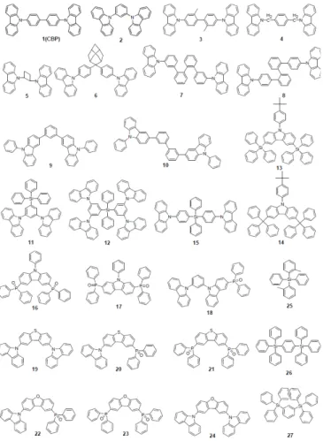
Figure 1. Chemical structures of blue phosphorescent hosts.
Figure 2. Chemical structures of blue phosphorescent dopants.
Figure 3. Chemical structures of yellow dopant materials.
Figure 4. Chemical structures of Orange dopant materials.
2. Phosphorescent Emitters
2.1. Phosphorescent blue host
Blue phosphorescent host materials are required to achieve high effi- ciency of lighting application of white OLEDs. Also, many studies are underway. Since triplet energy of blue phosphorescent dopant materials in general is 2.70~2.75 eV, host material should have higher triplet energy. When triplet energy of host material is lower than that of dop- ant material, back energy transfer can occur from the dopant to host.
Such back energy transfer can consequently show disadvantages like triplet exciton quenching and low device efficiency. Therefore, blue phosphorescent host materials must have triplet energy of 2.75 eV or higher in order to prevent back energy transfer of exciton.
Representative core structures with high triplet energy include carba- zole, arylsilan, dibenzofuran and dibenzothiophene. For the develop- ment of blue phosphorescent host materials with high triplet energy, it is not only necessary to have core structure but also to reduce con- jugation length for wide band gap. For example, introduction of SP
3carbon, silicon or phosphine oxide unit and introduction of sterically hindered structure can reduce the conjugation length of intramolecule.
As mentioned earlier, since triplet energy is extremely important for improvement of device performance in blue phosphorescent host mate- rials, we are going to focus on the introduction of phosphorescent host materials based on each core structure and their triplet energy.
Carbazole core has high triplet energy of 3.02 eV and hole transport properties, it can be used as a blue phosphorescent host materials[10].
Substitution position of carbazole or other units could affect on the triplet energy of the phosphorescent host material. Emitter 1, para-linked cabazoles with biphenyl, is the most widely used as a phosphorescent host material. However in case of emitter 1, triplet en- ergy was smaller at 2.6 eV than 2.7 eV of emitter 28 used as the dopant. This system is hard to achieve high efficiency due to back en- ergy transfer from emitter 28 to emitter 1[11]. In case of emitter 2, a derivative of carbazole that linked phenyl in meta position, high trip- let energy of 2.9 eV was shown for wide band gap and use as blue phosphorescent host material[12]. Emitter 3, a derivative of carbazole that linked 2,2’ position of biphenyl in para position, had similar chemical structure as emitter 1[13]. Triplet energy of emitter 3 was higher than emitter 1 at 3.0 eV. With the introduction of methyl group in biphenyl unit, emitter 32 was structurally distorted to maintain triplet energy of carbazole. Other phosphorescent host materials based on car- bazole core such as emitter 4[14], emitter 5[15], emitter 6[16], emitter 7[17], emitter 9[18], and emitter 10[18] are summarized in Table 1.
Triphenylsilyl unit was introduced to the carbazole core and thermal
stability could be improved without decreasing triplet energy of the
materials. While glass transition temperature of emitter 2 was 55 ℃,
temperature of emitter 11 which substituted triphenylsilyl group into
emitter 2 was increased to 101 ℃[19]. Emitter 12 also showed high
Emitter CIE (x, y) LE
a(cd/A) PE
b(lm/W) EQE
c(%) Reference
50 (0.15, 0.09) 2.63 1.96 5.17 [44]
51 (0.15, 0.12) 5.60 5.70 5.10 [45]
52 (0.15, 0.30) 7.90 6.80 - [46]
53 (0.15, 0.17) 8.44
d4.67
d6.83
d[47]
54 (0.15, 0.20) 10.90
d5.42
d7.72
d[47]
55 (0.15, 0.25) 11.20
d4.87
d7.34
d[48]
56 (0.15, 0.19) 9.45
d4.69
d7.15
d[48]
57 (0.15, 0.20) 9.79
d4.86
d7.35
d[48]
58 (0.15, 0.22) 9.12
d4.23
d6.34
d[48]
59 (0.15, 0.24) 10.10
d4.66
d6.66
d[48]
60 (0.14, 0.18) 7.79 4.33 6.54 [49]
61 (0.13, 0.17) 8.56 4.61 7.32 [49]
62 (0.14, 0.16) 9.11 6.13 8.16 [49]
63 (0.14, 0.15) 8.11 5.12 7.45 [49]
64 (0.17, 0.08) 4.90 - 6.10 [50]
65 (0.16, 0.08) 5.30 - 6.70 [50]
66 (0.16, 0.07) 5.40 - 6.80 [50]
67 (0.15, 0.11) 5.20 1.90 5.20 [51]
68 (0.15, 0.24) 10.50 4.00 6.40 [52]
69 (0.16, 0.11) 4.90 - 8.60 [53]
70 (0.16, 0.11) 4.90 - 8.60 [53]
71 (0.15, 0.14) 7.47 7.30 6.31 [54]
72 (0.15, 0.15) 6.40 3.84 5.26 [54]
73 (0.15, 0.10) 5.76 2.19 5.98 [54]
74 (0.15, 0.07) 1.72 0.65 5.10 [55]
75 (0.13, 0.21) 10.01 4.90 6.90 [56]
76 (0.15, 0.11) 5.66 6.13 5.02 [57]
77 (0.14, 0.09) - 4.20 5.40 [58]
78 - - 12.0 3.10 [62]
aLuminance efficiency. bPower efficiency. cExternal quantum efficiency. dValues collected at 20 mA cm-2.
Table 2. The Summary of the PL and EL Performance for the Emitters
Figure 5. Chemical structures of red dopant materials. Figure 6. Chemical structures of red dopant materials.
glass transition temperature of 148 ℃[20]. The triplet energy of emit- ter 11 was 2.90 eV and the triplet energy of emitter 12 was 3.01 eV.
Emitter 13[21], emitter 14[22] and emitter 15[23] were also developed by adopting phenyl carbazole with triphenylsilyl or diphenylsilane.
Those materials showed high triplet energy and high glass transition temperature.
Host materials with high triplet energy and charge transport charac- teristics were developed by introducing moieties such as dibenzothio-
phene core and dibenzofuran core in addition to phosphine oxide unit.
Phosphine oxide unit could enhance electron transport properties with-
out decreasing triplet energy of core structure. Emitter 16 including
two diphenylphosphine oxide units at 3,6 position of phenyl carbazole
showed high triplet energy of 3.02 eV and balanced charge transport
properties[24]. Emitter 17 which substituted diphenylphosphine oxide
units in 2,7 position of phenyul carbazole showed lower triplet energy
and band gap than emitter 16[25]. Emitter 18 which substituted diphe-
50
N
51
53
Figure 7. Chemical structures of symmetric or asymmetric DPA derivatives.
N
N 53
54
Figure 8. Chemical structures of fluorene derivatives including bulky tert-butyl group.
Si N
Si N
55
56
Si N
Si N
N Si
57
58
59
Figure 9. Chemical structures of fluorene derivatives including bulky silicon group.
N
N
N
N
N
N N
N
Si
Si
60 61
62 63
Figure 10. Chemical structures of spirofluorene derivatives.
Figure 11. Chemical structures of oligofluorene derivatives with propeller-like core.
nylphosphine oxide unit into emitter 2 had similar triplet energy as emitter 2 with improved electron transport properties[26]. Host materi- als with high triplet energy and bipolar charge transport ability were developed by substituting carbazole and diphenylphosphine oxide moi- ety into dibenzothiophene core or dibenzofuran core. High triplet en- ergy host materials of emitter 19, emitter 20, and emitter 21 were syn- thesized and charge transport properties were compared[27]. Emitter 20 having one carbazole and diphenylphosphine oxide unit in dibenzothio- phene core showed bipolar charge transport properties. Dibenzofuran derivatives of emitter 22, emitter 23, and emitter 24 were studied by manufacturing devices with single or mixed host structure[28].
Host materials of tetraphenylsilane core were synthesized to get high triplet energy. Host materials that use Si atom to disconnect con-
jugation of phenyl units could increase band gap and triplet energy.
Emitter 25[29,30], emitter 26[29,30] and emitter 27[30] were devel- oped by changing substitution positions and showed high triplet energy. But, deep HOMO level of emitter 25, emitter 26 and emitter 27 limits hole injection from hole transport layer to emitting layer and causes increase of driving voltage.
2.2. Phosphorescent blue dopant
Emitter 28 is a blue phosphorescent dopant very well known as
Firpic. However, many efforts for improvement were made as emitter
28 has greenish blue wavelength and short lifetime. Zhou’s group de-
veloped emitter 29, a homoleptic triscyclometalated iridium(III) com-
plex in which ligand is substituted as a type, to compare its EL perfor-
Me
Me
O C4H9O C4H9
O O C4H9 C4H9
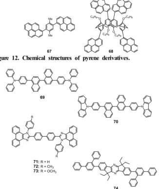
67 68
Figure 12. Chemical structures of pyrene derivatives.
N N
N N
N N
N
N N
N R
R 69
70
71: R = H 72: R = CH3
73: R = OCH3
74
Figure 13. Chemical structures of other categorized blue fluorescent emitters.
N S
B N
N
N N
Be ON
O
75 76 77
Figure 14. Chemical structures of donor/acceptor type derivatives and organometallic derivatives.
NSN
N N
S S
O O O O
78