Vol. 26, No. 6, 2017, 97-101
≫ 연구논문 ≪
슬러리 코팅 공정을 이용한 Fe 폼의 제조에 대한 연구
윤중열*·박다희*·양상선*·§왕제필**
*한국기계연구원 부설 재료연구소 분말기술연구실, **국립부경대학교 금속공학과
Fabrication of Fe Foam using Slurry Coating Process
Jung-Yeul Yun*, Dahee Park*, Sangsun Yang* and
§Jei-Pil Wang**
*Powder Technology Department, Korea Institute of Materials Science, Changwon 641-010, Korea
*Department of Metallurgical Engineering, Pukyong National University, Busan 608-739, Korea
요 약
메탈폼은 매우 많은 기공을 포함하는 세포상 구조를 갖는 고체금속을 일컫는다. 특히 관통 기공 같은 개기공들은 고온용 필터 및 촉매 지지체 등으로 산업적으로 많이 사용되고 있다. 본 연구에서는 슬러리 코팅공정으로 90% 이상의 기공율과 2 mm 이상의 기공크기를 갖는 Fe 폼을 제조하였다. 이때 Fe 분말과 Fe
2O
3분말의 혼합비를 달리하여 기공율과 기공크기를 제어하였다. 이를 위 해 우선 분말, 증류수 및 폴리비닐알콜(PVA)를 균일하게 혼합하여 슬러리를 제조하였다. Fe
2O
3분말의 혼합 비율이 증가할수록 PU 폼에 코팅된 슬러리의 양이 증가한 반면 Fe 폼의 수축 및 기공율은 각각 감소하였다.
주제어 :
메탈폼, 슬러리코팅, 소결, 기공, 마이크로CT
Abstract
Metal foams have a cellular structure consisting of a solid metal containing a large volume fraction of pores. In particular, open pores which are penetrable pores are necessary for industrial applications such as in high temperature filters and as support for catalysts. In this study, Fe foam with greater than 90% porosity and 2-mm pore size was successfully fabricated using a slurry coating process and the pore properties were characterized. The Fe and Fe2O3 powder mixing ratios were controlled to produce Fe foam samples with different pore sizes and porosity. First, the slurry was prepared through the uniform mixing of powders, distilled water, and polyvinyl alcohol(PVA). The amount of slurry coated with the PU foam increased with increasing Fe2O3 mix- ing powder ratio, but the shrinkage and porosity of the Fe foams decreased, respectively, with increasing Fe2O3 mixing powder ratio.
Key words : Metal foam, Slurry coating, Sintering, Porosity, Micro-CT
1. INTRODUCTION
In accordance with industrial development, the potential applications of environmental purification filters are
increasing. For example, they can be used in petrochemical filters, incinerator dust collectors, and the exhaust-gas purification devices of various internal combustion engines in automobiles. A porous material with high
· Received : November 15, 2017 · Revised : November 27, 2017 · Accepted : December 11, 2017
§
Corresponding Author : Jei-Pil Wang (E-mail : [email protected])
Department of Metallurgical Engineering, Pukyong National University, 365 Sinseon-ro, Nam-gu, Busan, 48547, Korea
ⓒThe Korean Institute of Resources Recycling. All rights reserved. This is an open-access article distributed under the terms of the
Creative Commons Attribution Non-Commercial License (http://creativecommons.org/licenses/by-nc/3.0/), which permits unrestricted
non-commercial use, distribution and reproduction in any medium, provided the original work is properly cited.
are being conducted at present.
In this study, a very simple slurry coating process was used to fabricate a porous metal with porosity of over 90%. The slurry coating process is a technique used in the fabrication process of porous metal materials.
In this process, after the slurry is fabricated by mixing an organic binder with a metal or alloy powder, it is coated on the PU foam structure. Then, debinding and sintering processes are performed4). The slurry coating process is advantageous to control pore control, because a pore structure and shape similar to these of the PU foam used as a template can be obtained. It also has the advantage of being able to produce porous metals of various structures without materials restrictions.
Since the porous metals used as the exhaust gas filters is required to have excellent heat and corrosion resistance that can withstand high temperature exhaust gas, the Fe alloy is preferentially used. Further, for use as a filter, large pores (2 mm or larger) and high porosity (90%
or higher) are required5). Various factors affecting pore size and the structure of Fe foam in the slurry coating process can be taken into consideration. In this study, Fe foam with a large pore size and high porosity is fabricated using the slurry coating process by mixing Fe and Fe2O3 (low-priced oxide powder at 1/5th the price of Fe powder) powders6). In particular, the variations in the size, structure, and organization of the pores according to changes in the Fe2O3 powder mixing ratio are analyzed.
2. EXPERIMENTAL
The components used here were Polyvinyl alcohol (PVA 1500CH2CH(OH), Junsei, Japan) as a binder, Fe
is then added so as to obtain a binder solution and powder ratio (wt%) of 40:60, respectively. Subsequently, the mixture is stirred for approximately 5 min, thereby fabricating a slurry. To examine the changes in the pore properties in response to varying Fe and Fe2O3 powder mixing ratios, the Fe and Fe2O3 powders were mixed with mixing ratios (wt%) of (100:0), (70:30), (50:50), (30:70), and (0:100). The PU foam was then added to the prepared slurry using roller and any over-coated slurry blocking the PU foam pores (10 ppi, Ecotech, Korea) was removed using air blowing, and drying was conducted at 80°C for 3 h. Based on the thermal analysis of the binder and PU foam7), debinding was conducted by heating the product up to 700°C at 3°C/min in air to completely remove the polyurethane foam and binder, and the debinded specimen was sintered again for 3 hours at 1,250°C in a H2 atmosphere (99.999%, 0.3 L/
min) to fabricate an Fe foam. Then, the slurry's viscosity (LVDV-II+P, Brookfield, U.S.A.), which was dependent on the mixing ratios of the Fe and Fe2O3 powders, and its weight, which depended on the number of coatings, were measured. The pore structure of the fabricated Fe foam was analyzed using X-ray micro computed tomo- graphy (CT, Skyscan 1272, Bruker, U.S.A.), and micro- structure and phase analyses were conducted using a scanning electron microscope (JSM-5800, Jeol, Japan) and X-ray diffraction (Cu kα radiation, D-MAX 2200, Rigaku, Japan).
3. RESULTS AND DISCUSSION
Fig. 1(a) shows the varying viscosity values of the fabricated slurries, according to the variations in the Fe and Fe2O3 powder mixing ratios given in the previous
section. In the figure, it can be seen that the value slurry viscosity showed 60, 120, 360, 780, and 2670 cP as the Fe2O3 content ratio was from 0, 30, 50, 70, to 100, respectively. This seems to occur because the total volume of powder added to a solvent of the same volume is increased from 5.09 to 7.63 cm3 as the Fe2O3 powder content increases, since the density of the Fe2O3 powder (5.242 g/cm3) is lower than that of the Fe powder (7.86 g/cm3).8) Fig. 1(b) shows the weight of the PU foam per unit volume after the slurry coating. It was found that, as the ratio of the Fe2O3 powder increased,
the slurry's viscosity increased. And the amount of slurry coated on the foam increased with the increase of coating number.
Fig. 2 shows the results of the XRD analysis of the Fe and Fe2O3 powders as raw materials and of the foam fabricated after sintering. As shown in the figure, the Fe and Fe2O3 powders are transformed into the Fe phase after reduction/sintering process. Table 1 shows the changes in shrinkage and porosity depending on the Fe2O3 powder content in the fabricated Fe foam. As can be seen in the figure, as the Fe2O3 powder content Fig. 1. Slurry viscosity and coated foam weight variations: (a) slurry viscosity depending on Fe2O3 powder ratios, (b) coated
weight per unit volume depending on coating number.
Fig. 2. X-ray diffraction patterns of (a) raw Fe powder, (b) raw Fe2O3 powder, and (c) Fe foam obtained through reduction and sintering process.
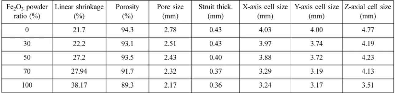
Table 1. Pore properties of Fe foam fabricated by slurry coating processes.
Fe
2O
3powder ratio (%)
Linear shrinkage (%)
Porosity (%)
Pore size (mm)
Struit thick.
(mm)
X-axis cell size (mm)
Y-axis cell size (mm)
Z-axial cell size (mm)
0 21.7 94.3 2.78 0.43 4.03 4.00 4.77
30 22.2 93.1 2.51 0.43 3.97 3.74 4.19
50 27.2 93.5 2.43 0.40 3.88 3.72 4.23
70 27.94 91.7 2.32 0.37 3.29 3.19 4.13
100 38.17 89.3 2.17 0.36 3.24 3.17 3.51
ratio increased from Fe: Fe2O3 = (100:0), (70:30), (50:50), (30:70), and (0:100), the Fe foam shrinkage gradually increased to 21.7, 22.2, 27.2, 27.94, and 38.17%, respectively. As regards the Fe2O3 powder, the shrinkage can be predicted to increase because the reduction- sintering is conducted in a reduction atmosphere. Further- more, it was found that the porosity of the fabricated Fe foam decreased to 94.3, 93.1, 93.5, 91.7, and 89.3%
as the Fe2O3 powder content was increased, following the ratios given above. It can be inferred that, as the Fe2O3 content ratio increases, the slurry coated on the polyurethane foam strutute becomes thicker because of the high viscosity of the slurry. In addition, pore blockage occurred in some areas, which means the cell structure of the foam was blocked. Also, the overall porosity was reduced because of the high shrinkage occurring during the reduction-sintering of the Fe2O3 powder.
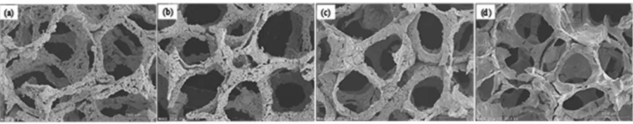
Fig. 3 shows the microstructure of the Fe foam fabricated using the slurry coating process, and it can be confirmed that, as the Fe2O3 powder content ratio increased, the pore size was reduced but the strut thick- ness remained almost the same. Also, because the average Fe2O3 powder particle size is approximately 13 times less than that of Fe powder, as the Fe2O3 powder content ratio is increased, the microstructure of the foam becomes very dense. It can be inferred that this change in the strut microstructure will affect the mechanical properties of the Fe foam; thus, there are plans to conduct a mechanical property evaluation in the future.
From the above results, it was found that the amount of slurry coated on the PU foam can be controlled during the slurry coating stage by changing the Fe2O3 and Fe powder content ratios, and the pore size, strut thickness,
and cell size of the Fe foam fabricated using this method can be controlled. In brief, it was confirmed that Fe foam that has a minimum of 89% porosity can be fabricated using the slurry coating process. This foam has a pore size with a minimum value of 2 mm and a minimum cell size of 3 mm, regardless of the Fe2O3 powder content ratio.
4. CONCLUSION
In this study, Fe foam was fabricated using a slurry coating process, and the ratios of the Fe and Fe2O3 powders used in this process were varied. Then, the resultant pore properties were analyzed. As the ratio of Fe2O3 powder increased, the amount of slurry coated on the PU foam also increased, while the shrinkage of the fabricated Fe foam increased from 21.7 - 38.17% and the porosity decreased from 94.3 - 89.3%. The results of the micro X-ray analysis of the fabricated Fe foam pore structure indicated that, as the Fe2O3 powder content increased, the pore size and unit cell size decreased, whereas the strut thickness had similar values of approximately 0.4 mm irrespective of the amount of slurry coated on the PU. Furthermore, as the Fe2O3 powder content ratio increased, it was found that the struts in the fabricated Fe foam had a denser structure.
Acknowlegement
The work was supported by a grant from the Fundamental R&D Program for Core Technology of Materials funded by the Ministry of Trade, Industry &
Energy, Republic of Korea.
References
1. J. Banhart, 2001 : Prog. Mater. Sci., 46, pp559.
2. M. A. Alvin, T. E. Lippert, and J. E. Lane, 1991 : Ceram.
Bull., 70, pp1491.
3. J. H. Choi, I. S. Ahn, Y. C. Bak, S. Y. Bae, S. J. Ha, and H. J Jang, 2004 : Powder Technol., 140, pp98.
4. J. Banhart, 2000 : Adv. Eng. Mater., 2, pp188.
5. Y. M. Jo, R. B. Hutchison, and J. A. Raper, 1997 : Pow- der Technol., 91, pp55.
6. C. Y. Zhao, T. J. Lu, H. P. Hodson, and J. D. Jacson, 2004 : Mater. Sci. Eng. A., 367, pp123.
7. Y. Boonyongmaneerat and D. C. Dunand, 2008 : Adv.
Eng. Mater., 10, pp379.
8. O. Andersen, U. Waag, L. Schneider, G. Stephani and B.
Kieback, 2000 : Adv. Eng. Mater., 2 pp192.
윤 중 열
• 한국과학기술원 재료공학과 공학박사
• 현재 한국기계연구원 부설 재료연구소 분말기술연구실 책임연구원
박 다 희
• 한국과학기술원 EEWS 대학원 공학 석사
• 현재 한국기계연구원 부설 재료연구소 분말기술연구실 연구원
양 상 선
• 서울대학교 기계공학과 공학박사
• 현재 한국기계연구원 부설 재료연구소 분말기술연구실 책임연구원
왕 제 필