수직형 소형풍력터빈의 비정상 익력 평가
이상문1⋅김철규1⋅전석윤1,2⋅알사지드1,3⋅장춘만1,3,†
1한국건설기술연구원, 2한양대학교 대학원 기계공학과, 3과학기술연합대학원대학교 건설환경공학
Analysis of Unsteady Blade Forces in a Vertical-axis Small Wind Turbine
SANG-MOON LEE
1, CHUL-KYU KIM
1, SEOK-YUN JEON
1,2, SAJID ALI
1,3, CHOON-MAN JANG
1,3,†1Department of Land, Water and Environment Research, Korea Institute of Civil Engineering and Building Technology, 283 Goyangdae-ro, Ilsanseo-gu, Goyang 10223, Korea
2Department of Mechanical Engineering, Hanyang University, 55 Hanyangdaehak-ro, Sangnok-gu, Ansan 15588, Korea
3Smart City Construction Engineering, University of Science & Technology (UST), 217 Gajeong-ro, Yuseong-gu, Daejeon 34113, Korea
†
Corresponding author :
[email protected]Received
4 April, 2018Revised
28 April, 2018Accepted
30 April, 2018Abstract >> In the present study, unsteady flow analysis has been conducted to investigate the blade forces and wake flow around a hybrid street-lamp having a vertical-axis small wind turbine and a photovoltaic panel. Uniform velocities of 3, 5 and 7 m/s are applied as inlet boundary condition. Relatively large vortex shed- ding is formed at the wake region of the photovoltaic panel, which affects the in- crease of blade torque and wake flow downstream of the wind turbine. It is found that blade force has a good relation to the variation of the angle of attack with the rotation of turbine blades. Variations in the torque on the turbine blade over time create a cyclic fluctuation, which can be a source of turbine vibration and noise.
Unsteady fluctuation of blade forces is also analyzed to understand the nature of the vibration of a small wind turbine over time. The detailed flow field inside the turbine blades is analyzed and discussed.
Key words : Vertical-axis small wind turbine(수직형 소형 풍력터빈), Numerical sim- ulation(수치해석), Pressure fluctuation(압력변동), Torque(토오크), Blade force(익력)
1. Introduction
In recent years, interest in renewable energy has increased due to the exhaustion of fossil fuels, the growth in environmental pollution and the growth in attention paid to clean energy generation systems,
such as tidal power, wave-power, wind power and
solar energy generation, etc. Furthermore, the concept
of hybrid renewable energy systems (HRES), which
combine two or more renewable energy generation
systems (wind-photovoltaic, biomass-wind-fuel cell
and wind-solar-fuel cell, etc.)
1-3), has been introduced
and suggested to enhance system efficiency and performance. On the other hand, Tjiu et al.
4,5)eval- uated the Darrieus type vertical-axis small wind tur- bine (VAWT) and concerned about the opportunity of multi-megawatt Darrieus VAWT development.
This paper focuses in particular on the VAWT and photovoltaic power system, which is suitable for res- idential areas thanks to its advantages of low cut-in velocity and low noise level. To evaluate the tran- sient performance characteristics of VAWT, un- steady flow characteristics should be analyzed through a numerical analysis or experiment.
Many numerical and experimental studies have been conducted to investigate the transient perform- ance characteristics of VAWT. Danao et al.
6)carried out an experimental investigation on a wind tunnel scale vertical axis wind turbine with unsteady wind condition, in which the wind speed was 7 m/s with both 7% and 12% fluctuations in wind velocity at a frequency of 0.5 Hz. Danao et al.
7)also performed numerical analysis using Reynolds-averaged Navier- Stokes (RANS) analysis to investigate the effects of steady and unsteady wind on the performance of a wind tunnel scale VAWT. Almohammadi et al.
8)in- vestigated three methods, namely the General Richardson Extrapolation method (GRE), the Grid Convergence Index method (GCI) and the fitting method, in order to understand the convergence be- havior of straight blade VAWT, and obtained a mesh independent solution of the power coefficient pro- duced numerically by the straight blade VAWT. Lee and Lee
9)evaluated the aerodynamic noise generated from a 10 kW wind turbine using numerical pre- diction and measurement. Jaohindy et al.
10)per- formed unsteady Reynolds-averaged Navier-Stokes (URANS) analysis to simulate the transient behavior of the Savonius rotor with different aspect ratios.
Wekesa et al.
11)proposed a numerical approach to in-
vestigate wind energy potential under real unsteady wind conditions in Marsabit and Garissa, which are the rural-urban towns in Kenay. They introduced a two-dimensional computational fluid dynamics (CFD) method to analyze unsteady wind energy po- tential and power predictions of VAWTs. Nobile et al.
12)investigated the performance of an open and augmented rotor of a Darrieus straight-bladed VAWT using RANS analysis. They constructed 2-dimen- sional numerical model for VAWT through the mesh sensitive test, turbulence model selection and time step effect test. The 2-dimensional numerical model successfully validated with the experimental results.
Tai et al.
13)developed the Algorithm for Darrieus vertical-axis wind turbine, the submitted LDWT code using by the consideration of the local Reynolds number using real wind speed on the Darrieus blade.
They investigated the phenomenon of the turbine blades with respect to the tip speed ratio, angle of at- tack and azimuthal angle variations.
However, while much research has considered the two-dimensional turbine blade model, a three-di- mensional unsteady flow simulation for the turbine blade of a hybrid street-lamp has not been performed until now.
In the present study, three-dimensional unsteady
flow analyses have been carried out to analyze blade
forces and wake flow around a hybrid street-lamp
having a vertical-axis small wind turbine and a pho-
tovoltaic panel. Three kinds of inlet velocities, 3, 5,
and 7 m/s, are tested by three-dimensional URANS
analysis. Detailed flow characteristics around the
hybrid street-lamp, pressure variations with time
scales on the blades' surfaces and torque of turbine
blades are analyzed through numerical analyses.
Fig. 1. Configuration of a hybrid street-lamp
Fig. 2. Power curve of a wind turbine
(a) computational domain
(b) computational grids Fig. 3. Computational domain and grid system
2. Small Hybrid Wind Turbine
Fig. 1 shows the configuration of a hybrid street- lamp considered in the present study. The hybrid street-lamp consists of four parts, which are the tur- bine blade, the photovoltaic panel, the lamppost and the control & storage device. The 200 W VAWT is selected as a reference model. The reference model has three turbine blades. Blade height and radius are 1.22 m and 1.03 m, respectively. The photovoltaic panel has a size of 0.55 m × 1.1 m, and the diameter of the lamppost is 0.216 m. The total height of lamp and mid-span of turbine blades are 6.640 m and 6.030 m, respectively. In general, the VAWT oper- ates with a rotor speed of 50-180 rpm. Performance curve of the VAWT is shown in Fig. 2.
3. Numerical Simulation and Boundary Conditions
3.1 Numerical simulation
General analysis code, ANSYS-CFX 14.0
14), was used to analyze three-dimensional unsteady flow around the hybrid street-lamp. The shear stress trans- port (SST) model with automatic turbulent wall function is used to evaluate the eddy viscosity terms of the RANS and URANS equations. Fig. 3 shows the computational domain and grid system of the hy- brid street-lamp employed in the present study.
Considering the stable outlet flow condition, the dis- tance between the turbine blade and the outlet plane is maintained at 25 times the turbine blade diameter.
The computational domain has three parts; namely,
the rotation part of turbine blades, the stationary
parts of the main body and the outer region.
Table 1. Boundary conditions
Case 1 Case 2 Case 3
Wind inlet velocity [m/s] 3 5 7
Rotational frequency of a
turbine blade [RPM] 114 190 266
Working fluid Air at 25 °C
Wall Free slip condition
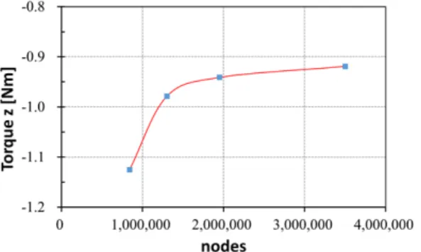
Fig. 5. Flow field around VAWT by RANS Fig. 4. Grid dependency test
Unstructured hybrid meshes were applied in all of the computational domain. The grid dependency test has been performed to obtain the optimal grid sys- tem, which has grid efficiency and reliability. Fig. 4 shows the result of the grid dependency test. As shown in the figure, the grid system having about 1.9 million nodes has been selected as the optimal num- ber of grids. The first grid points adjacent to the walls are placed at y+ less than 1.0, which is required to implement the low-Reynolds-number SST model.
3.2 Boundary conditions
The boundary conditions of three cases, inlet ve- locities of 3, 5, and 7 m/s, are shown in Table 1.
Uniform flows and relative pressures are applied at the inlet and the outlet of computational domain for all three cases. The rotational frequency of a turbine blade is determined while the value of the tip speed ratio keeps 4.
4. Results and discussions
4.1 Validation of a Turbine Performance
For the validation of the numerical solutions, the wind power has been compared to the experimental
results according to inlet velocities as shown in Fig.
2. The figure shows that the power obtained through the numerical simulation matches well with the ex- perimental results. The computed power at the inlet velocities of 3, 5, and 7 m/s has a maximum 10 per- cent error with the experimental data. The compar- isons between the numerical and experimental re- sults show that the wind power of the turbine blade has been simulated correctly.
4.2 Flow Characteristics at the time-averaged flow
First of all, three-dimensional RANS analysis had been performed to confirm the flow characteristics around the small hybrid wind turbine according to wind inlet velocities.
Fig. 5 shows the flow field around VAWT by
RANS. The flow fields consist of two different flow
types, which are the wake flow by turbine blade and
(a) V
in = 3 m/s(b) V
in = 5 m/s(c) V
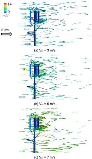
in = 7 m/sFig. 6. Velocity vector colored by velocity for the time-aver-
aged flow fieldFig. 7. Power coeficient variation with wind speed (λ=2.05)
photovoltaic panel. The wake flow by photovoltaic panel affects the direction of the wake flow by tur- bine blades.
Fig. 6 shows the velocity vector of the time-aver- aged flow field around VAWT for three different wind inlet velocities of 3, 5, and 7 m/s. The three cases have similar flow characteristics around the small hybrid wind turbine, such as wake flow behind the turbine blades and photovoltaic panels. However, the direction of the downstream of the turbine blades is moved to the positive z direction with the increase of wind inlet velocity. It can be expected that the dis- tance between turbine blades and photovoltaic pan- els should be designed carefully to reduce the effect of the wake flow behind photovoltaic panels to ach- ieve higher performance of a hybrid wind turbine.
4.3 Performance analysis at the time-averaged flow
The performance of VAWT can be analyzed with two parameters, the tip speed ratio (λ) and the power coefficient (Cp), which are obtained as follows:
(1)
(2)
where, ω represents angular velocity of the rotor blade, r is the distance between the rotation axis and the rotor blade, and V
wrepresents the wind velocity.
On the other hand, P
mand P
trepresent the mechan- ical power and the total power of the wind, respectively. The definitions of P
tand P
ware as fol- lows:
(3)
(4)
where, T is the blade torque, and ρ and A represent
Fig. 8. Turbine torque at the inlet wind velocity of 5 m/s
Fig. 9. Limiting streamlines on blade pressure surface at the
inlet wind velocity of 5 m/s for the 10th blade rotationFig. 10. Pressure fluctuations at the five positions on blade
suction surface at the inlet wind velocity of 5 m/s for the 9th and 10th blade rotations(a) force
(b) torque
Fig. 11. Force and torque on the turbine blades at the inlet
wind velocity = 5 m/s for the 10th blade rotationfluid density and the swept area of the VAWT, respectively.
Fig. 7 shows the Cp variation with wind speed fixed at the tip speed ratio (λ) of 2.05. The values of Cp are decreased when the wind speed increases.
Generally, the value of Cp is constant with fixed λ.
However, as can be seen from Figs. 6 and 7, the Cp is
decreased because the effect of the wake flow by photovoltaic panel is increased with the increase of the wind speed in this case.
4.4 Performance analysis at the time-averaged flow
The time step convergence had been confirmed with the turbine blade torque with three directions at the inlet wind velocity of 5 m/s using three-dimen- sional URANS, as shown in Fig. 8. As shown in this figure, the transitional feature can be found until the 5th rotation of the turbine blade, and the periodic convergence is achieved after that. Therefore, the three-dimensional unsteady behaviors of the VAWT are investigated using the results of the 10th rotation.
The comparison of limiting streamlines on blade
pressure surface at the inlet wind velocity of 5 m/s for the 10th blade rotation of unsteady and steady simulation is shown in Fig. 9. From the steady flow calculation, a local flow separation region is ob- served near the blade trailing edge. The local flow separation is also presented in the unsteady calcu- lation, while its magnitude and positions differ over time. All limiting streamlines and the flow down- stream of separations show a slight average tendency toward the positive z direction. It can be expected that this flow phenomenon is caused by wake flow behind the photovoltaic panels.
Fig. 10 shows the pressure fluctuation at the five positions (located on mid-span line) on blade suction surface at the inlet wind velocity of 5 m/s for the 9th and 10th blade rotations. Relatively high pressure is observed near the blade leading edge, and periodic pressure fluctuation is found for all velocities.
Fig. 11 shows the force and torque variations on the turbine blades for the 10th blade rotation. It can be seen that the force of x and y directions have close relationships with the torque of y and x directions.
Time delay of one-third blade rotation is found at the force x and y because there are three turbine blades.
5. Conclusion
Three-dimensional unsteady flow analysis of a hybrid street-lamp having a vertical-axis small wind turbine and a photovoltaic panel have been per- formed to understand the flow characteristics inside the wind turbine for the front wind flow to the photo- voltaic panels and to analyze the turbine blade force and the unsteady wake flow phenomenon. The con- clusions derived from this analysis are as follows:.
1) The direction of the downstream behind the tur- bine blades is affected by the wake flow behind the photovoltaic panels according to the wind inlet
velocity. It is found that the wake flow can deterio- rate the performance of the wind turbine.
2) Due to the wake flow behind the photovoltaic panel, a local flow separation is observed near the blade trailing edge. Relatively high pressure is ob- served near the blade leading edge where periodic pressure fluctuation is found.
3) The fluctuation phenomenon of the torque and forces over time is observed in the results of unsteady flow analysis, and could be a source of vibration.
4) A systematic design, which considers actual site conditions such as variations in wind speed and direction and unsteady flow characteristics between turbine blades and photovoltaic panels, is required to reduce the vibration and to enhance the performance of a wind turbine.
후 기
This work was supported by the new and renew- able energy core technology program of the Korean Institute of Energy Technology Evaluation and Planning (KETEP), granted financial resources from the Ministry of Trade, Industry and Energy, Republic of Korea (No. 20153010130310).
References
1. T. Markvart, “Sizing of hybrid photovoltaic-wind energy systems”, Solar Energy, Vol. 57, No. 4, 1996, pp. 277-281.
2. H. Natto, “Renewable energy generation systems”, International Journal of Scientific & Engineering Research, Vol. 4, No. 12, 2013, pp. 2001-2008.
3. H. G. Geovanni, L. D. Orlando, P. D. Rafael, S. J. Alberto, and P. J. Sebastian, “Analysis of the current methods used to size a wind/hydrogen/fuel cell-integrated system: A new perspective”, International Journal of Energy Research, Vol. 34, No. 12, 2010, pp. 1042-1051.
4. W. Tjiu, T. Marnoto, S. Mat, M. H. Ruslan, and K. Sopian,
“Darrieus vertical axis wind turbine for power generation I:
Assessment of Darrieus VAWT configurations”, Renewable
Energy, Vol. 75, 2015, pp. 50-67.
5. W. Tjiu, T. Marnoto, S. Mat, M. H. Ruslan, and K. Sopian,
“Darrieus vertical axis wind turbine for power generation II: Challenges in HAWT and the opportunity of mul- ti-megawatt Darrieus VAWT development”, Renewable Energy, Vol. 75, 2015, pp. 560-571.
6. L. A. Danao, O. Eboibi, and R. Howell, “An experimental investigation into the influence of unsteady wind on the performance of a vertical axis wind turbine”, Applied Energy, Vol. 107, 2013, pp. 403-411.
7. L. A. Danao, J. Edwards, O. Eboibi, and R. Howell, “A nu- merical investigation into the influence of unsteady wind on the performance and aerodynamics of a vertical axis wind turbine”, Applied Energy, Vol. 116, 2014, pp. 111-124.
8. K. M. Almohammadi, D. B. Ingham, L. Ma, and M.
Pourkashan, “Computational fluid dynamics (CFD) mesh independency techniques for a straight blade vertical axis wind turbine”, Energy, Vol. 58, 2013, pp. 483-493.
9. S. Lee and S. Lee, “Numerical and experimental study of aerodynamic noise by a small wind turbine”, Renewable
Energy, Vol. 65, 2014, pp. 108-112.
10. P. Jaohindy, S. McTavish, F. Garde, and A. Bastide, “An anal- ysis of the transient force acting on Savonius rotors with dif- ferent aspect ratios”, Renewable Energy, Vol. 55, 2013, pp.
286-295.
11. D. W. Wekesa, C. Wang, Y. Wei, J. Kamau, and L. A. Danao,
“A numerical analysis of unsteady inflow wind for site spe- cific vertical axis wind turbine: a case study for Marsabit and Garissa in Kenya”, Renewable Energy, Vol. 76, 2015, pp.
648-661.
12. R. Nobile, M. Vahdati, J. F. Barlow, and Mewburn-Crook,
“A Unsteady flow simulation of a vertical axis augmented wind turbine: a two-dimensional study”, Journal of Wind Engineering and Industrial Aerodynamics, Vol. 125, 2014, pp. 168-179.
13. F. Z. Tai, K. W. Kang, M. H. Jang, Y. J. Woo, and J. H. Lee,
“Study on the analysis method for the vertical-axis wind turbines having Darrieus blades”, Renewable energy, Vol.
54, 2013, pp. 26-31.
14. ANSYS 14.0 user manual, 2011, ANSYS Inc.