Introduction
Convective heat loss represents one of the three basic modes of heat transfer, and it dominates over radiative and conductive heat loss (Papadakis et al., 1992; Kreith et al., 2012; Kakac et al., 2013). This thermal exchange pheno- menon involves mass transfer (Baïri et al., 2014). Natural convection from horizontal, isothermal, and rectangular plates has been the subject of many experimental and theoretical investigations (Sharma and Adelman, 1969;
Yang et al., 1991; Radziemska and Lewandowski, 2005;
Corcione, 2008).
During this period, a large number of correlations have been developed to fit the heat transfer data (Khalifa, 2001).
However, natural convection from horizontal screens has got lower consideration as compared to pure free convection from horizontal mechanical surfaces. The outcome is that
information about horizontal screens is sometimes unpredic- table, and the physical nature of the boundary layer flow is insufficiently known. Free convection from thermal screens is vital to the researchers and greenhouse growers.
The phenomenon of free, forced, and mixed convective heat transfer from greenhouse-covering materials and plastic shading nets to the natural environment has been previously investigated by few studies (Papadakis et al., 1992; Abdel- Ghany et al., 2015). These studies dealt with homogenous (screens made of one material only) and symmetric (screens with identical sides) materials. With the development of new greenhouse screens (heterogeneous and asymmetric), their application to new cases is limited.
In order to determine the convective heat transfer coeffici- ent, it is necessary to know whether the exchange is due to free or forced convection or a combination of both (Papadakis et al., 1992). In convective heat transfer, two dimensionless numbers, the Reynolds number (Re) and Grashof number (Gr), are important for the characterization of flow. The ratio Gr.Re
-2defines the importance of natural convection
Measurement of Convective Heat Transfer Coefficients of Horizontal Thermal Screens under Natural Conditions
Adeel Rafiq
1, Wook Ho Na
2, Adnan Rasheed
1, Hyeon Tae Kim
3, and Hyun Woo Lee
1,2,4*
1
Department of Agricultural Engineering, Kyungpook National University, Daegu 41566, Korea
2
Institute of Agricultural Science and Technology, Kyungpook National University, Daegu 41566, Korea
3
Department of Bio-Industrial Machinery Eng., Gyeongsang National Univ. (Insti. of Agric. & Life Sci.), Jinju 52828, Korea
4
Smart Agriculture Innovation Center, Kyungpook National University, Daegu 41566, Korea
Abstract. Convective heat transfer is the main component of greenhouse energy loss because the energy loss by this mechanism is greater than those of the other two components (radiative and conductive). Previous studies have examined the convective heat transfer coefficients under natural conditions, but they are not applicable to symmetric thermal screens with zero porosity, and such screens are largely produced and used in Korea. However, the properties of these materials have not been reported in the literature, which causes selectivity issues for users. Therefore, in this study, three screens having similar color and zero porosity were selected, and a mathematical procedure based on radiation balance equations was developed to determine their convective heat transfer coefficients. To conduct the experiment, a hollow wooden structure was built and the thermal screen was tacked over this frame; the theoretical model was applied underneath and over the screen. Input parameters included three components: 1) solar and thermal fluxes; 2) temperature of the screen, black cloth, and ambient air; and 3) wind velocity. The convective heat transfer coefficients were determined as functions of the air–screen temperature difference under open-air environmental conditions. It was observed from the outcomes that the heat transfer coefficients decreased with the increase of the air–screen temperature difference provided that the wind velocity was nearly zero.
Additional key words : absorption, convective heat transfer coefficient, pyranometer, thermal screens
DOI https://doi.org/10.12791/KSBEC.2020.29.1.9
eISSN 2288-100X*Corresponding author: [email protected]
Received October 08, 2019; Revised November 28, 2019;
Accepted December 03, 2019
with respect to forced convection (Issa and Lang, 2013).
It is well established that forced convection prevails when Gr ㆍRe
-21, forced convection is negligible when Gr ㆍRe
-21, and both natural and forced convection are significant when Gr ㆍRe
-21 (Incropera et al., 2007).
In this study we describe a new radiation balance method for heterogeneous (made of more than one material) symmetric screens. The first purpose of this study is to determine the heat flux and convective heat transfer coefficient of greenhouse screens. The second is to draw a relationship between convective heat transfer coefficients, air velocity, and air –screen temperature differences. The final purpose is to separate natural, forced, and mixed convection by using the Gr ㆍRe
-2ratio.
Materials and Methods
1. Material Properties and Composition
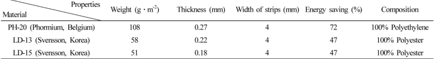
During this experiment, three materials of similar color and category (symmetric, i.e., with identical sides) but different composition were tested. The properties and the nature of the tested materials are presented in Table 1.
PhormiTex PHL 20 (PH-20) is an energy-saving gable screen. Luxous-1547 D FR (LD-15) combines good heat- retaining properties with superior light-diffusion and light-transmission qualities. The diffusion brings light to the plants from various directions, reducing the overheating of upper areas. The main function of Luxous-1347 D FR (LD-13) is saving energy through achieving maximum light transmission.
2. Experimental setup
This research was carried out on a building roof in order to get clear sky radiation. A hollow wooden frame was built for the investigation. The bottom part of the frame was covered with black cloth with known radiometric properties
( τ
b=0, ρ
b=0.07, Ɛ
b=0.93). The setup had a 3-m
3volume (3 m width×2 m length×0.5 m height). Fig. 1 demonstrates the dimensions of the setup, positions of the equipment and Laboratory setup. Figs. 2 and 3 depict the radiation exchanged between the sky, screen, and black cloth; the unknown parameters are highlighted in red in the figure. Downward longwave (Q
aand Q
c) and shortwave (S
aand S
c) radiations were measured with a pyrgeometer and pyranometer, respectively, while upward longwave fluxes (Q
band Q
d) were computed from the difference between the net radiome- ter and downward fluxes. Upward shortwave radiations (S
band S
d) were measured using an inverted pyranometer. Two thermocouple wires, with very thin diameters, were used to measure the surface temperature of the thermal screen and black cloth. All measured parameters were recorded at 10-minute intervals and saved in a different data logger.
Table 2 shows the list of equipment and data loggers.
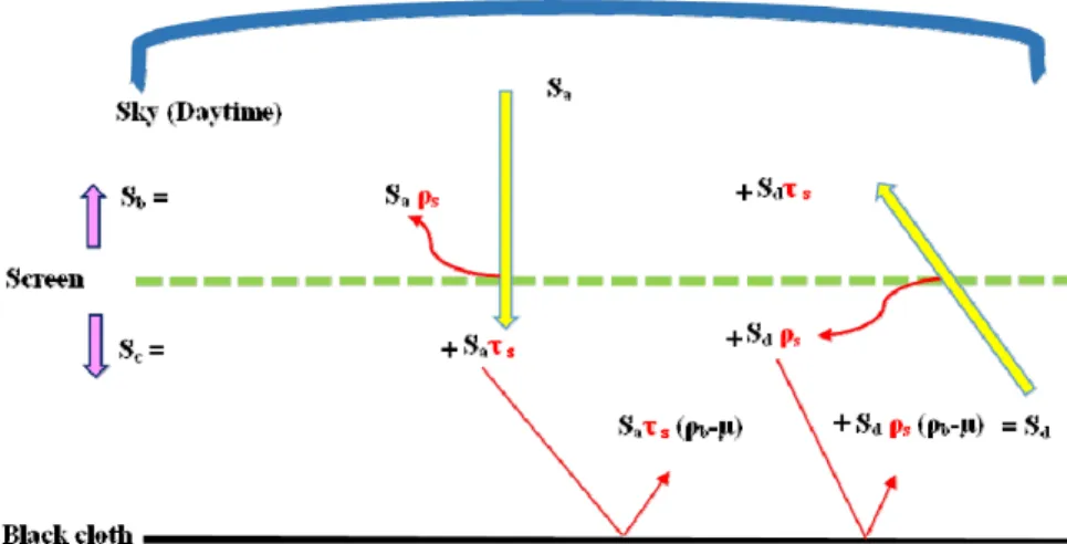
3. Measurement of radiative properties during day time The outgoing shortwave radiation equation above the screen surface (S
b) is given below in W ㆍm
-2.
S
b= ρ
s· S
a+ τ
s· S
d(1)
Where ρ
sis the reflectance of screen, τ
sis the transmittance of screen and S
ais the downward sky radiation in W ㆍm
-2, S
dis the radiations coming from black cloth toward screen in W ㆍm
-2.
The outgoing shortwave radiation equation over the black surface (S
c) and below the screen surface is given below in W ㆍm
-2.
S
c= τ
s· S
a+ ρ
s· S
d(2)
Equations 1 and 2 are used for symmetric materials in order to solve for two unknowns (ρ
s& τ
s). The corresponding
Table 1. Properties of tested materials.
Properties
Material Weight (g ㆍm
-2) Thickness (mm) Width of strips (mm) Energy saving (%) Composition
PH-20 (Phormium, Belgium) 108 0.27 4 72 100% Polyethylene
LD-13 (Svensson, Korea) 58 0.22 4 47 100% Polyester
LD-15 (Svensson, Korea) 51 0.18 4 47 100% Polyester
(a)
(b)
Fig. 1. Experimental setup’ diagrams (a) Schematic (b) Laboratory arrangement.
Fig. 2. Ideal drawing of inward (S
aand S
d) and outward (S
band S
c) radiations from screen.
absorptance (α
s) is calculated by using Kirchhoff’s law of thermal radiation ( α
s=1- ρ
s- τ
s).
4. Measurement of radiative properties during night time The outgoing longwave radiation equation above the screen surface (Q
b) is given below in W ㆍm
-2.
Q
b= E + ρ
L· Q
a+ τ
L· Q
d(3)
Where E is the emissive power of screen in W ㆍm
-2, it was determined by Stefan-Boltzmann’s law , Q
ais the downward sky radiation in W ㆍm
-2, Q
dincoming longwave radiation toward the screen, above the black cloth in W ㆍm
-2, ρ
Lis the longwave reflectance of screen, τ
Lis the longwave transmit- tance of screen.
The outgoing long-wave radiation equation over the black surface (Q
c) and below the screen surface is given below in W ㆍm
-2.
Q
c= E + τ
L· Q
a+ ρ
L· Q
d(4) Equation of Q
dis given below
Q
d= E
b+ ( ρ
b+ µ) · E+ (ρ
b-µ) · ρ
L· Q
d+ ( ρ
b-µ) · τ
L· Q
a(5)
When equations (3 to 5) were solved simultaneously in Matlab (Matlab R2018B, MathWorks, USA) by iteration method, equation 5 caused compatibility issue even though the number of equations are equal to number of unknowns (E, ρ
Land τ
L). Thus, in order to make these equations Fig. 3. Ideal drawing of inward (Q
aand Q
d) and outward (Q
band Q
c) radiations from screen.
Table 2. List of measuring sensors.
Parameter Unit Sensor Range Data logger
Net longwave radiation W ㆍm
-2NR Lite2 Net Radiometer
(Kipp and Zonen, Netherlands) 0.2 –100 μm LR 5041 (Hioki, Japan) Downward & upward shortwave
radiations W ㆍm
-2CMP3 Pyranometer
(Kipp and Zonen, Netherlands) 300 –2800 nm LR 5041 (Hioki, Japan) Downward longwave radiation (Q
a) W ㆍm
-2CGR3 Pyrgeometer
(Kipp and Zonen, Netherlands) 4.5 –42 μm 21x Micrologger (Campbell Scientific, Inc. USA) Downward longwave radiation (Q
c) W ㆍm
-2IR02 Pyrgeometer
(Hukseflux, Netherlands) 4.5 –40 μm CR300
(Campbell Scientific, Inc. USA) Temperature/relative humidity °C / % Hobo Pro v2 U23-002
(Onset, USA)
-40 –70°C 0 –100 %
Hobo Pro v2 U23-002 (Onset, USA) Surface temperature °C T-type thermocouple wires -270 –370°C Hobo UX120-014M
(Onset, USA)
compatible to solve, µ (10
-6) is subtracted from reflected portion of τ
LㆍQ
aand ρ
LㆍQ
d,and the same number is added into the reflected portion of E in equation 5. Micro (µ) is the smallest assumed number act as tolerance for the reflectance of the black cloth (ρ
b) and with no significant effect on value but it helps to solve these equations. Subtraction and addition is based on the strength of radiation. As emissive power of screen has higher strength than other two factors (ρ
LㆍQ
d& τ
LㆍQ
a) because it is coming towards black cloth without striking any surface. E
bis the emissive power of black cloth in W ㆍm
-2which was determined by Stefan- Boltzmann’s law.
Kirchhoff’s law of thermal radiation gives the following equation
τ
L+ ρ
L+ α
L=1 (6)
Where α
Lis the longwave absorptivity.
Measurement of absorption of radiations for 24 hours The absorbed thermal and solar radiations by the symme- tric screen (A) were determined as
A = α
L· (Q
a+Q
d) + α
s· (S
a+S
d) (7)
Where α
sis absorptivity value in shortwave radiation region.
Over a small interval of time, the energy balance equation, per unit area (m
2), of a horizontal symmetric screen under steady-state natural condition is given by
A- 2 · E – 2 · C
m-a= 0 (8)
Where ‘C
m-a’ is the convective heat transfer from screen to air.
The convective heat transfer coefficient between the symmetric screen and air (h
m−a) is given by
h
m−a= C
m-a/ (T
m-T
a) (9)
Where T
mis the materials surface temperature (K) and T
asurrounding air temperature (K).
The ratio of the buoyancy forces and the inertial forces is expressed as:
Gr · Re
-2= (g · L · β · ΔT)/v
2(10)
Where g is the gravitational acceleration (m ㆍs
-2), L is the characteristic length of the screen (m) and we used length of the setup (3 m) as characteristic length, β is the volumetric thermal expansion coefficient (K
-1), for an ideal gas β equals inverse of the absolute temperature, ΔT (K) is the temperature difference between screen and surrounding air, and v is the velocity (m ㆍs
-1).
Results and Discussion
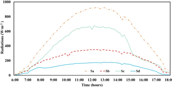
Fig. 4 exhibits the incoming and outgoing shortwave radiations of PH-20. Downward and upward radiations were directly measured by separate pyranometers. Outward radiations S
band inward radiations S
cwere the same in the early morning and later in the evening. The strengths of the radiations, received at the S
csensor, were weaker due to the low angle of sunlight even though the radiations received at the S
asensor were greater than two hundred W ㆍm
-2from 3:00 pm to 4:00 pm.
Table 3 displays the average values of radiative properties in both the shortwave and longwave regions. Thermal radiations values are adopted from our previous study (Rafiq, 2019). LD-15 and LD-13 showed high values of absorption in the shortwave region. This high absorption can be seen by taking the S
c/S
a, which indicates how much solar radiation passed through the material. Fig. 5 shows that LD-15 and LD-13 showed extremely low values of S
c/S
aas compared to PH-20. Radiations generated by the materials were ignored in this calculation as suggested by previous study (Cohen et al., 2014). The effect of the high absorption can also be seen on the temperature difference graph in Fig. 6.
LD-15 and LD-13 had a greater tendency to retain energy, so they exhibited high temperature differences as compared to PH-20, which has a very low absorption value. This table also shows the range of Reynolds numbers over each sample examined. The determination of whether flow is laminar or turbulent is based on the Reynolds number. All the Reynolds numbers calculated for each material were less than 10
5. This shows that the flow over the sample screens was in the laminar range.
The convective heat exchanges between the upper or
lower side of the thermal screen and air were calculated, and they are demonstrated in Fig. 7. LD-15 and LD-13 transferred high amounts of heat flux to the air during the daytime because both had high absorption in the shortwave region, which subsequently raised its temperature as compared to
ambient air temperature during the daytime. Cloudiness condition can affect the value of heat flux, as the flux is purely based upon solar, sky and materials radiations. So, when one source completely or partially obstructed, it may affect the value. Among these three sources of radiations, Fig. 4. Inward (S
aand S
d) and outward (S
band S
c) shortwave radiations for PH-20.
Table 3. Absorption and Reynolds number estimated during experiment.
Sample screen Absorption
Reynolds number shortwave region longwave region
PH-20 0.08 0.49 1.77 –1.82 E+04
LD-13 0.87 0.46 1.42 –1.44 E+04
LD-15 0.89 0.45 8.84 –8.92 E+03
Fig. 5. Ratio between radiations before (S
a) and after (S
c) passing screens.
only the solar radiations can be blocked. LD-15 material showed dome shape curve of heat flux during the daytime which indicate the clear sunny day. Due the presence of partial clouds in the sky, other two materials showed variations in the values.
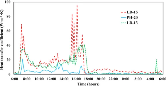
The time progression of the convective heat transfer coefficients for the thermal screens examined is shown in Fig. 8. Variations in the values are related to the fluctuations in the Gr ㆍRe
-2ratio (Abdel-Ghany et al., 2015). Values of heat transfer coefficients mainly depend on the screen –air temperature difference and wind velocity. The amount of convective heat transfer is mainly based upon the local wind velocity, and it has a great effect on the determination of
whether the convection is free or forced (Papadakis et al., 1992; Smith, 2010). Thus, wind velocity is required to compute Gr ㆍRe
-2. Local wind velocity was measured at 1.25 m (from roof surface) height over each sample screen.
During this experiment, it was observed that the value of wind velocity was not more than 1 m ㆍs
-1. The effect of low wind speed can be seen in Fig. 9. The ratio of Gr ㆍRe
-2shows higher values due to the low wind speed, which is directly related to purely free convection. More than 98% of values of this ratio for all tested samples were greater than 1.
During the experiment of LD-15 and LD-13, it was observed that the ratio gave higher values during the daytime. The reason of these greater values simply related to the velocity Fig. 6. Difference between ambient and screen temperature calculated for each sample.
Fig. 7. Time progressions for the convective heat flux.
square factor in the denominator of the equation 10. The other four factors (g, L, β & ΔT) have direct relationship with ratio but have minor effect on the values. Even though temperature difference value increased significantly during the experiment but the impact the on ratio was negligible due the presence of thermal expansion coefficient, as the values of the β were not more than 0.0035. Thus, velocity is the only deciding factor. So, when the value of velocity was less than 1, it was further reduced by the square, and it produced a greater value, which showed the dominant free flow. The wind speed was relatively constant and low, so in
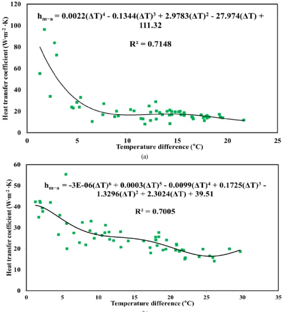
this experiment, only the correlation between the temperature difference and convective heat transfer coefficient was drawn. Fig. 10 shows this relation between ΔT and h
m−afor LD-15 and LD-13. Equations are also displayed for both materials. These equations can be applied to similar kinds of materials to calculate the convective heat transfer coefficients under similar kinds of environment conditions. Both materials showed that as the temperature difference increases the value of h
m−adecreases. In case of LD-15, this decrease was exponential. As it can be seen in the Fig. 10a when temperature difference increased from 0 to 7°C, the value of h
m−aFig. 8. Time progressions for the convective heat transfer coefficient.
Fig. 9. Time progression for ratio GrㆍRe
-2to display convection regimes on screen surface.
decreased from 88 to 17 W ㆍm
-2ㆍK. After this exponential change the value of h
m−aremained stable even when the change in temperature difference value reached up to 22°C.
In case of LD-13, steady decrease was observed.
Conclusion
A mathematical model was presented to experimentally calculate the convective heat transfer coefficients of energy- saving screens. The procedure was based on radiation balance equations, and it was applied to a wooden frame on which
horizontal screens were tacked. Basic parameters required to calculate the coefficient value were radiative properties and air –screen temperature difference. Equipments used for this study were solar and thermal radiation sensors (Net Radiometers, Pyrgeometer, and Pyranometer), temperature sensors (Thermocouple and Hobo Pro v2 U23-002) and anemometer. The convection heat transfer was always purely free for all tested samples, the Reynolds numbers showed that the airflow was in the laminar regime, and the wind velocity in the local area was less than 1 m ㆍs
-1. The convective heat transfer coefficients were characterized as (a)
(b)
Fig. 10. Relationship between air–screen temperature difference and convective heat transfer coefficient measured during daytime for (a) LD-15 (b)
LD-13.
functions of the air –screen temperature difference. It was found that during the daytime, the air –screen temperature difference increased and the screens having high solar radiation absorption (LD-13 and LD-15) indicated a decrea- sing trend.
Acknowledgements
This research was supported by Basic Science Research Program through the National Research Foundation of Korea (NRF) funded by the Ministry of Education (NRF- 2019R1I1A3A01051739). This work was supported by the Korea Institute of Planning and Evaluation for Technology in Food, Agriculture, Forestry and Fisheries (IPET) through Agriculture, Food and Rural Affairs Research Center Support Program, funded by Ministry of Agriculture, Food and Rural Affairs (MAFRA) (717001-7). This research was supported by Kyungpook National University Development Project Research Fund, 2018.
Literature Cited
Abdel-Ghany, A.M., I.M. Al-Helal, M.R. Shady, and A.A.
Ibrahim. 2015. Convective heat transfer coefficients between horizontal plastic shading nets and air. Energ. buildings.
93:119-125.
Baïri, A., E. Zarco-Pernia, and J.M.G.D. María. 2014. A review on natural convection in enclosures for engineering applica- tions. The particular case of the parallelogrammic diode cavity. Appl. Therm. Eng. 63(1):304-322.
Cohen, S., M. Möller, M. Pirkner, and J. Tanny. 2014. Measuring radiometric properties of screens used as crop covers. Acta
Hortic. 1015:191-200.
Corcione, M., 2008. Natural convection heat transfer above heated horizontal surfaces. 5th WSEAS Int. Conf. on Heat and Mass Transfer (HMT’08), Acapulco, Mexico, January 25-27.
Incropera, F.P., A.S. Lavine, T.L. Bergman, and D. P. DeWitt.
2007. Fundamentals of heat and mass transfer, Wiley.
Issa, S. and W. Lang. 2013. Minimum detectable air velocity by thermal flow sensors. Sensors. 13(8):10944-10953.
Kakac, S., Y. Yener, and A. Pramuanjaroenkij. 2013. Convective heat transfer, CRC press.
Khalifa, A.J.N., 2001. Natural convective heat transfer coefficient – a review:I. Isolated vertical and horizontal surfaces. Energy conversion and management. 42(4):491-504.
Kreith, F., R.M. Manglik, and M.S. Bohn. 2012. Principles of heat transfer, Cengage learning.
Papadakis, G., A. Frangoudakis, and S. Kyritsis. 1992. Mixed, forced and free convection heat transfer at the greenhouse cover. J Agr Eng Res. 51:191-205.
Radziemska, E. and W. M. Lewandowski. 2005. The effect of plate size on the natural convective heat transfer intensity of horizontal surfaces. Heat Transfer Eng. 26(2): 50-53.
Rafiq, A., W.H. Na, A. Rasheed , H.T. Kim, and H.W. Lee 2019. Determination of Thermal Radiation Emissivity and Absorptivity of Thermal Screens for Greenhouse. Protected Hort. Plant Fac. 28(3).
Sharma, K.K. and M. Adelman. 1969. Experimental study of natural convection heat transfer in a non‐newtonian fluid:
Part II. Horizontal plate. Can. J. Chem. Eng. 47(6):556-558.
Smith, J.O. 2010. Determination of the convective heat transfer coefficients from the surfaces of buildings within urban street canyons. PhD Diss., University of Bath, United Kingdom.
Yang, W.J., H. Takizawa, and D.L. Vrable. 1991. Natural
convection from a horizontal heated copper-graphite compo-
site surface. ASME J. Heat Transfer.113(4):1031-1033.
온실 스크린의 대류열전달계수 측정
라피크아딜
1ㆍ나욱호
2ㆍ라쉬드아드난
1ㆍ김현태
3ㆍ이현우
1,2,4*
1
경북대학교 농업토목공학과,
2경북대학교 농업과학기술연구소,
3경상대학교 생물산업기계공학과,
4