Robot Controller Design with Embedded RTOS *
Hong, Seon Hack
**ㆍYoun, Jin Sub
***임베디드 RTOS 기반의 로봇 컨트롤러 설계
홍 선 학ㆍ윤 진 섭
<Abstract>
In this paper, We designed the robot controller with Linux OS, Cygwin under the Marvell Monahan PXA320 embedded platform. Cygwin is a collection of tools for using the Linux-like environment for commercially released x86 32 bit and 64 bit versions of Windows and is a DLL that acts as a Linux API emulation layer providing substantial Linux API functionality. TinyOS-2. x is a component based embedded OS by UC Berkeley and is an open-source OS designed for interfacing the sensor application with specific C-language. The results of experiment are described to show the improvement of sensor interfacing functionality under the PXA320 embedded RTOS platform.
Key Words : Android Platform, Cygwin, JAVA SDK, TinyOS
Ⅰ. 서론
1)
The Cygwin is a Linux-like environment for Windows. It consists of a DLL which acts an emulation layer providing substantial POSIX(Portable Operating System Interface) system call functionality, and a collection of tools, which provide a Linux look and feel. The Cygwin DLL works with all x86 and AMD64 versions of Windows NT4. The API the single Unix specification and then Linux practice. The major differences between Cygwin and Linux is the C library. Cygwin began development in 1995 at Cygnus * 본 연구는 2009학년도 서일대학 교내학술연구비지원으로 수
행되었음
** 서일대학 컴퓨터전자과 교수(교신저자)
*** 서일대학 컴퓨터전자과 교수
Solutions. The first thing done was to enhance the development tools(gcc, gdb, gas, etc) so that they could generate and interpret Win32 native object files.
The next task was to port the tools to Win NT/9x. So we could have done this by rewriting large portions of the source to work within the context of the Win32 API. But this would have meant spending a huge amount of time on each and every tool. Instead, we took a substantially different approach by writing a shared library(the Cygwin DLL) that adds the necessary UNIX-like functionality missing from the Win32 API(fork, spawn, signals, sockets, etc). We call this new interface the Cygwin API[1].
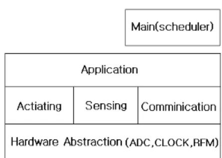
TinyOS is an open-source operating system designed for wireless embedded sensor networks. It
Fig 1. TinyOS Application Layer
features a component-based architecture which enablesrapid innovation and implementation while minimizing code size as required by the severe memory constraints inherent in sensor networks.
TinyOS's component libarry includes network protocols, distributed services, and data acquisition tools - all of which can be used for a custom application. TinyOS's event-driven execution model enables fine-grained power management yet allows the scheduling flexibility made necessary by the unpredictable nature of wireless communication and physical interfaces[2-3].
Ⅱ. Basic Theory
This chapter provides a fundamental overview of the Hardware Abstraction Architecture(HAA) of TinyOS. The HAA for TinyOS 2.0 balances the conflicting requirements of code reusability and portability on the one hand and efficiency and performance optimization on the other. Figure 1 shows the three layer design that gradually adapts the capabilities of the underlying hardware platforms to the selected platform-independent hardware interface between the operating system and the application code. At the same time, it allows the applications to utilize a platform's full capabilities - exported at the second layer, when the performance requirements overweigh the need for cross-platform compatibility.
2.1 Architecture
In the proposed architecture of Fig 1, the hardware abstraction functionality is organized in three distinct layers(Hardware Presentation/ Adaptation/ Interface
layers) of components. Each layer has clearly defined responsibilities and is dependent on interfaces provided by lower layers. The capabilities of the underlying hardware are gradually adapted to the established platform-independent interface between the operating and the applications.
The components belonging to the HPL are positioned directly over the HW/SW interface. As the name suggests, their major task is to “present” the capabilities of the hardware using the native concepts of the operating system. They access the hardware in the usual way, either by memory or by port mapped I/O. In the reverse direction, the hardware can request servicing by signaling an interrupt. The adaptation layer components represent the core of the architecture. They use the raw interfaces provided by the HPL components to build useful abstractions hiding the complexity naturally associated with the use of hardware resources. Due to the efficiency requirements of sensor networks, abstractions at the HAL level are tailored to the concrete device class and platform. Instead of hiding the individual features of the hardware class behind generic models, HAL interfaces expose specific features and provide the
“best” possible abstraction that streamlines application
Fig 2. Packet processing Procedure
development while maintaining effective use ofresources. The final tier in the layer is formed by the HIL components that take the platform-specific abstractions provided by the HAL and convert them to hardware-independent interfaces used by cross-platform applications. These interfaces provide a platform independent abstraction over the hardware that simplifies the development of the application software by hiding the hardware differences[4-6].
2.2 Scheduler and Packet Processing
In TinyOS 2. x, the scheduler is a TinyOS component. Every scheduler must support C tasks. It may also support any number of additional task interfaces. The basic task in TinyOS is parameterless and FIFO. Tasks continue to follow the C semantics of task and post, which are linguistic shortcuts for declaring an interface and wiring it to th scheduler component.
We use the Mote-PC serial communication with packet source. This method allow us to collect data from the network, send commands to motes, and monitor network traffic. We use the Java-based infrastructure for communicating with motes. The basic abstraction for mote-PC communication is a packet source. A packet source is exactly that : a communication medium over which an application can receive packets from and send packets to a mote.
MIG(Message Interface generator) tool takes three basic arguments : what programming language to generate code for (Java, Python, or C), which file in which to find the structure, and the name of the structure. The TinyOS toolchain makes this process easier by providing tools for automatically generating
message objects from packet descriptions. Given a sequence of bytes, the MIG-generated code will automatically parse each of the fields in the packet, and it provides a set of accessors and mutators for printing out received packets or generating new ones.
Figure 2 illustrates the graphical overview of the Packet Processing procedure[7-8].
2.3 Boot Sequence
The TinyOS boot sequence has four steps : Scheduler initialization, Component initialization, Signal that the boot process has completed, and Run the scheduler. The first boot step is to initialize the scheduler. If the scheduler were not initialized before the components, component initialization routines would not be able to post tasks. While not all components require tasks to be posted, this gives the flexibility required for those components that do. The component initialization is dependencies between different parts of the system. These are handled in three ways in TinyOS:
- Hardware specific initialization issues are handled directly by each platform's component.
- System services are typically written to be independently initializable.
- When a service is split into several components, the init interface for one of these components may well call Init interfaces of the other components forming
Fig 3. Blockdiagram of embedded platform
the service, if a specific order is needed.Once all initialization has completed, Boot event is signaled. Components are now free to call start() and other commands on any components they are using.
Once the application has been informed that the system as booted and started needed services. TinyOS enters its core scheduling loop. The scheduler runs as long as there are tasks on the queue. As soon as it detects an empty queue, the scheduler puts the microcontroller into the lowest power state allowed by the active hardware resources[9-10].
Ⅲ. Sensing over the Radio
In this paper, sensing is an integral part of robot's sensor applications. Usually sensing involves two tasks : configuring a sensor and reading the sensor data. The first task is tricky, because the configuration details of sensors will be different form platform to platform.
However, the second task - reading the sensor data - can be solved so that the sensor application can collect sensor data even though it is agnostic to the platform it is running on.
3.1 Running the Java GUI
To visualize the sensor reading on our PC, start a serial forwarder and make sure it connects to the node on which we have installed in the Base-station application. At first, We must have installed the Oscilloscope application and depending on which hardware we use, Oscilloscope uses a timer to periodically sample the default sensor of a platform.
When it has gathered 10 sensor readings, it puts them
into a message and broadcasts that message via the communication interface. Figure 3 illustrates the graphical overview of the embedded platform.
3.2 Communication Interface
In this paper, we could use a number of interfaces to abstract the underlying communications services and a number of components that provide these interfaces. All of these interfaces and components use a common message buffer abstraction, called message_t, which is implemented as a nesC struct. There are a number of interfaces and components that use message_t as the underlying data structure.
- Packet : provides the basic accessors for message_t abstract data type. This interface provides commands for clearing a message's content's, getting its payload length, and getting a pointer to its payload area.
- Send : provides the basic address-free message sending interface. This interface provides commands and cancelling a pending message send, and an event to indicate whether a message was sent successfully or not.
- Receive : provides the basic message reception
Fig 4. The component graph of GenericComm
interface. This interface provides an event forreceiving messages.
Since it is very common to have multiple services using the same radio to communicate, TinyOS provide the Active Message(AM) layer to multiplex access to the radio. Am type are similar in function to the Ethernet frame type filed, IP protocol filed, and the UDP port in that all of them are used to multiplex access to a communication service. AM packets also includes a destination filed, which stores an “AM address” to address packets to particular motes[11].
3.3 Sending a Message over the Radio
In this paper, We have defined a message type for our application. We want a timer-driven system in which every firing of the timer results in (i) incrementing a counter, (ii) displaying a number of bits of the counter, and (iii) transmitting the node's id and counter value over the radio. To implement this program, we follow a number of simple steps, as described in the next procedures. First, we need to identify the interfaces that provide access to the radio and allow us to manipulate the message_t type.
Second, we must update the module block in the application nc program by adding uses statements for the interfaces we need. Third, we need to declare new variables and add any initialization and start/stop code that is needed by the interfaces and components.
Fourth, we must add any calls to the component interface we need for our application. Fifth, we need to implement any events specified in the interfaces we plan on using. Sixth, the application configuration interface must be updated by adding a components statement for each component we sue that provides
one of the interface we choose earlier. Finally, we need to wire the interface used by the application to the components which provide those interfaces[12-15].
Now that we have an application that is transmitting messages, we could write code that, upon receiving a message, sets the device of the counter in the message. If two motes are programmed with our modified application, then each will display the other's mote's counter value. If the motes go out of range, then the sensor will stop changing. We can even investigate link asymmetry by trying to get one mote's display to keep blinking while the other mote's display stop blinking.
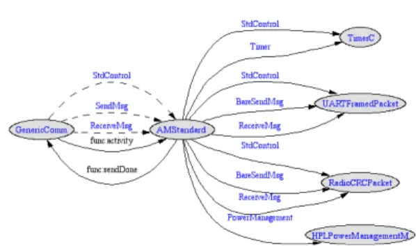
Figure 4 displays the component graph of GenericComm.
In this figure, StdControl means the standard control interface, Timer means provides a generic timer that can be used to generate events at the regular intervals, and BareSendMsg means functionality for sending a raw packet buffer : unaware of message structure(besides length)[16-17].
Ⅳ. Embedded Controller Design
In this chapter, we describe the characteristics of embedded RTOS controllers which include MSP430f1611, mixed signal micro-controller and cc2420, RF chip.
4.1 Mixed Signal Controller
The Texas Instruments MSP430f1611 of ultralow power micro-controllers consist of several devices featuring different sets of peripherals targeted for various applications. The architecture, combined with five low power modes is optimized to achieve extended battery life in portable measurement applications. The device features a powerful 16-bit RISC CPU, 16-bit registers, and constant generators that attribute to maximum code efficiency. The digitally controlled oscillator(DOC) allows wake-up from low-power modes to active mode in less than 6. This device has two built-in 16-bit timers, a fast 12-bit A/D converter, dual 12-bit D/A converter, one or two universal serial synchronous/ asynchronous communication interfaces (USART), , DMA, and 48 I/O pins, In addition, it offers extended RAM addressing for memory-intensive applications and large C-stack requirements.
The RF chip, cc2420 has high performance and low power 8051 micro-controller core, and 2.4GHz IEEE 802.1.5.4 compliant RF transceiver. This device has 32, 64, or 128 KB in-system programmable flash, and 8KB SRAM, 4KB with data retention in all power modes.
We use only a single crystal needed for mesh network systems and two powerful USARTs with support for several serial protocols[18-19].
4.2 NesC Language
In this paper, we implement controller with nesC which is a new language for programming structured component-based applications. The nesC language is primarily intended for embedded systems such as sensor networks. nesC has a C-like syntax, but supports the TinyOS concurrency model, as well as mechanisms for structuring, naming, and linking together software components into robust network embedded systems. The nesC has a several features.
First, nesC applications are built out of components with well-defined, bidirectional interfaces. Second, nesC defines a concurrency model, based on tasks and hardware event handlers, and detects data races at compile time.
There are two types of components in nesC:
modules and configurations. Modules provide application code, implementing one or more interface.
Configurations are used to assemble other components together, connecting interfaces used by components to interfaces provided by others. This is called wiring.
Every nesC application is described by a top-level configuration that wires together the components inside. In nesC, downcalls are generally commands, while upcalls are events. An interface specifies both sides of this relationship.
Figure 5. shows the Internal procedure of sensor available on the msp430-based platforms.
In this procedure we use the JNI object file which could generate the native code(libhello-jni. so) for Android and JNI source file(hello-jni. c) which control external device for serial communications.
Fig 5. Configuration of Internal Procedure
Fig 6. Acceleration Sensor Result
4.3 Sensor Applications
We implemented the embedding sensor controller with ADXL311 which is provided with Analog Devices company. The ADXL311 is a dual-axis acceleration measurement system on a single monolithic IC. The output signals are analog voltage proportional to acceleration and are capable of measuring both positive and negative accelerations to at least ± .
The accelerometer can measure static acceleration forces, such as gravity, allowing it to be used as a tilt sensor. We used the ADXL311 as a tilt measurement of embedded robot controller. One of the most popular applications is tilt sensing device.
An accelerometer uses the force of gravity as an input vector to determine the orientation of an object in space [20-21].
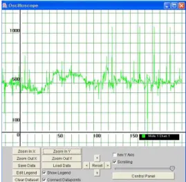
Figure 6 shows the experimental result with Sensor network, ADX311 to be used as a tilt sensor in the embedded controller. These images would pop up a window containing a graphical display of the sensor readings from the sensor board. It connects to the
serial forwarder over the network and retrieves packet data, parses the sensor readings from each packet, and draws the information on the graph.
The x-axis of the graph is the packet counter number and the y-axis is the sensor reading. There are several function keys to adjust the graph image which can be changed with Zoom In and Out, Clear or Load Data, and Scrolling bars[22-23].
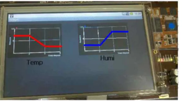
Figure 7 shows the Data-logging result for temperature and humidity for H-mote sensors with the Android platform embedded PXA320 interfacing USN(User Sensor Network) vis RF communication.
At first, we used the log-Cat functions with Eclipse for verifying the sensor data, and then setup the user interfacing Java program for sensor data as below Figure 7.
Fig 7. Sensing Data for Android Platform
Ⅴ. Conclusions
In this paper, we made the robot controller with embedded system. This controller, as a TinyOS platform sensor based system to be used under the Marvell PXA320 embedded platform, is implemented by TinyOS environment. TinyOS-2. x is a component based embedded system and is an open-source basis for interfacing with accelerometer sensor application.
The experiments are described to show the improvement of sensor interfacing functionality under the PXA320 embedded RTOS platform.
For flexibility and expandability, the designed platform has many expansion ports. The results of experiment are described to show the flexibility of mobile devices, such as smart phone or portable electronics devices for Android. We will experiment the results of this paper in detail to be broaden the scope of sensor interface and design considerations.
참고문헌
[1] 김명호, Cygwin과 함께 배우는 C 프로그래밍, 홍릉 출판사, 02. 2010.
[2] Levis, Philip, TinyOS Programming, Cambridge University Press, 04. 2009
[3] Matischek, Rainer, A TinyOS-Based Ad Hoc Wireless Sensor Network, VDM Verlag, 07. 2008.
[4] Marvell PXA320 Processor, Graphics and Input Controller, December 14, 2006.
[5] Marvell PXA320 Processor, Serial Controller Configuration, December 15, 2006.
[6] Mary Campione, Kathy Walrath, The Java Tutorial, Object-Oriented Programming for the Internet, Addison-Wesley, 2001.
[7] 김휴찬, 고완기, 박상열, “Java 기반 실시간센서 데 이터스트림처리 및 임베디드 시스템 구현,” 디지털 산업정보 학회, 4권, 2호, 2008.
[8] Summerfield, Mark, Programming in Python 3, Addison-Wesley Professional, 11. 2009.
[9] Philip Levis, TinyOS 2.0 Overview, Computer Systems Laboratory Stanford University, 10. 2006.
[10] Philip Levis, TinyOS Programming Guide, Computer Systems Laboratory Stanford University, 10. 2006.
[11] 홍선학, “UML기반의 창의공학용 로봇설계, 한국통 신학회,” 제33권, 제10호, 2008, pp. 343-349.
[12] 홍선학, “GUI환경을 갖는 퍼지기반 이동로봇제어,”
대한전자공학회, 제43권, IE편, 제4호, 2006, pp.
340-347.
[13] 홍선학, “센서결합을 이용한 이동로봇제어,” 대한전 자공학회, 제42권, TE편, 제2호, 2005, pp. 91-98.
[14] 홍선학, “영상 추적을 이용한 이동로봇제어,” 대한 전자공학회, 제42권, TE편, 제4호, 2005, pp.
201-208.
홍 선 학
Hong, Seon Hack
1985년 광운대학교 전기공학과 학사졸업 1988년 광운대학교 전기공학과 석사졸업.
1994년 광운대학교 대학원 박사 졸업.
1992년~현재 서일대학 컴퓨터전자과 교수
관심분야 : 제어, 컴퓨터응용, 로봇 분야 등 E-mail : [email protected]
윤 진 섭
Youn, Jin Sub
1991년 9월~현재
서일대학 컴퓨터전자과 교수 2002년 2월 동국대학교 전자공학과 (공학박사)
관심분야 : 정보기술 E-mail : [email protected]
논문접수일 : 2010년 8월 31일
수 정 일 : 2010년 10월 15일(1차), 11월 10일(2차) 게재확정일 : 2010년 11월 18일
[15] 홍선학, “MCU 플랫폼 창의 공학용 로봇 설계,” 디 지털 산업정보 학회, 제5권, 4호, 2009.
[16] 김정원, 신진철, 박형근, “Zigbee를 이용한 사용자 인식기반의 헬스케어시스템구현,” 디지털 산업정보 학회, 4권, 3호, 2008.
[17] Philip Levis, Simulating TinyOS Applications in TOSSIM, Computer Systems Laboratory Stanford University, 08. 2003.
[18] Nagy, Chris, Embedded Systems Design Using the Ti Msp430 Series, Newnes, 09. 2003.
[19] Luecke, Jerry, Analog and Digital Circuits for Electronic Control System Applications, Newnes, 09. 2004.
[20] Philippe Coiffet, An Introduction to ROBOT TECHNOLOGY, 1982.
[21] PXA320_Monahans_P_DM_Vol[1]+Rev_0.95 System and Timer Developers, 11, 7, 2006.
[22] Reto Meyer, Professional Android 2 Application Development, Wrox, 02. 2010.
[23] Wirfs-Brock,. R., Wilkerson. Designing Object- Oriented Software, Englewood Cliffs, NJ. : Prentice-Hall. 2002.
▪저자소개▪