3축 MEMS 가속도 센서를 이용한 걸음 수 측정을 위한 중력 제거 및 백터 전환 알고리즘
1)김 승 영, 권 구 인*
Gravity Removal and Vector Rotation Algorithm for Step counting using a 3-axis MEMS accelerometer
Seung-Young Kim, Gu-In Kwon*
요 약
최근, 다양한 형태의 웨어러블 컴퓨팅 디바이스와 이에 따른 응용 프로그램이 개발되고 있으며, 이들 중에서 헬 스 케어의 한 영역으로 웨어러블 컴퓨팅 디바이스를 이용하여 개인의 운동량은 측정하는 다양한 연구가 진행되고 있다. 본 논문에서는 가장 기초적인 운동인 걸음걸이 측정 알고리즘으로 중력 제거 및 백터 회전(Gravity Removal and Vector Rotation) 알고리즘을 제안하고, 이를 위한 실험으로 보행 또는 주행 중인 개인의 다양한 위치에 부착한 웨어러블 디바이스에 장착된 3축 MEMS 가속도 센서로부터 획득된 가속도 값을GRVR 알고리즘을 이용하여 걸음 수를 측정한다. GRVR은 가속도 센서로 획득된 3축 가속도 값으로 부터 중력에 의한 가속도 분은 저대역 필터를 이용하여 제거 하고, 이 후 각각의 가속도 값에서 직류 성분 제거 및 센서 축 회전 보상인 GRVR 알고리즘으로 보행 혹은 주행 중에 순수하게 걸음걸이에 의하여 발생하는 가속도 변화분 만을 추출한다. 실험 결과 로 웨어러블 디바이스를 개인의 허리 중앙 혹은 우측에 부착한 경우 GRVR 알고리즘을 이용한 걸음 수 측정은 99.4%의 정확도, 또한 손목에 부착한 경우 상용 3축 가속도 만보계의 83%보다 정확한 91.1%의 정확도를 확인 하였다.
▸Keywords : 웨어러블 디바이스, MEMS, 3축 가속도 센서, 중력 제거 및 백터 회전.
Abstract
In this paper, we propose Gravity Removal and Vector Rotation algorithm for counting steps of wearable device, and we evaluated the proposed GRVR algorithm with Micro-Electro-Mechanical (MEMS) 3-axis accelerometer equipped in low-power wearable device while the device is mounted
∙ 제1저자 : 김승영 ∙교신저자 : 권구인
∙ 투고일 : 2014. 1. 9, 심사일 : 2014. 3. 25, 게재확정일 : 2014 . 4. 15.
* 인하대학교 컴퓨터정보공학과(Dept. of Computer Information and Science, Inha University)
※ 이 논문은 인하대학교의 지원에 의하여 연구되었음.
on various positions of a walking or running person. By applying low-pass filter, the gravity elements are canceled from acceleration on each axis of yaw, pitch and roll. In addition to DC-bias removal and the low-pass filtering, the proposed GRVR calculates acceleration only on the yaw-axis while a person is walking or running thus we count the step even if the wearable device’s axis are rotated during walking or running. The experimental result shows 99.4% accuracies for the cases where the wearable device is mounted in the middle and on the right of the belt, and 91.1% accuracy which is more accurate than 83% of commercial 3-axis pedometer when worn on wrist for the case of axis-rotation.
▸Keywords : Wearable device, 3-axis accelerometer, Gravity Removal and Vector Rotation algorithm.
I. INTRODUCTION
Step counting is a well known to be an effective method of recording the physical activities of athletes as well as the elderly and obese. Some health guidelines specifically recommend that adults should take 10,000 steps per day, even though this is not reliable associated with any significant improvement in health outcomes compared an alternative activity goal or no goal at all[1].
Nevertheless, the obese can calculate how many calories they are burning by walking or running by counting steps [2] [3]. For example, a man of 73kg can burn off 116kCal by walking 10,000 steps per a day [4].
There are many types of pedometers on the market, with various prices, uses interfaces and accuracies, and hundreds of pedometers applications are now available in the Android and iPhone marketplaces [5]. However, most of these digital pedometers need to be mounted on the wearer’s belt or trousers to minimize interfering accelerations caused by loose attachment, wearer gait, changes of direction. In the worst case, a wrist-mounted pedometer can have a 30% in the number of fewer
steps recoded because the acceleration axis change because the wearer’s arms move while walking or running [6]. A pedometer that incorporates a micro electro-mechanical systems(MESMS) sensor will be designed to measure accelerations in the vertical direction (yaw axis) relatively large periodic changes when a person is walking [7][8].
The value of this vertical acceleration depends on how the wearable device is worn, but often a pocket or back-pack, and wrist is not vertical. Mounting wearable device on a belt or backpack, wearing it on the chest, or put in a pocket will cause the forward (roll-axis) and side (pitch-axis) acceleration to be measured rather than the vertical acceleration (yaw-axis) [9] measuring only is likely to produce an incorrect step count, no matter how the wearable device is worn [10].
In this paper, we propose the, gravity removal and vector rotation (GRVR) to filter analog-to-digital-convertor (ADC) noise, the constant acceleration due to gravity, and the distortion in acceleration caused by a changing axis of measurement. We evaluate this algorithm using the TI eZ430-Chronos development platform, which reads a 3-axis accelerometer sensor and transmits periodically ADC values to a host PC. We analyzed each acceleration for different ways of mounting a
wearable device, including on the shoes, on the belt, on the chest and on the wrist. The eZ430-Chronos software development tool is an integrated, wearable, wireless development system that is based on the CC430F6137. It can be used as a reference platform for timepiece systems, a display for personal area networks, or as a wireless sensor node for remote data collection [11].
To evaluate GRVR, we conducted three experiments in which the walker or runner wear the eZ430-Chronos as a digital wearable device on the middle of their belt, on the right side of their belt and on the wrist, while walking at specified speeds on a treadmill, as depicted in Fig. 1. During a test, the value of the acceleration-along each axis is transmitted to the PC and entered directly into spreadsheet. GRVR is then applied to these accelerations, and we compare the calculated number of steps with data from commercially available string-leveraged pedometers [12]. The results obtained using GRVR are over 99.4%
accurate for belt mounting and 91.1% accurate for wrist mounting.
Fig. 1. Wearable Device's Mounting location.
그림 1. 웨어러블 디바이스의 부착 위치.
II. AN ALGORITHM FOR COUNTING STEPS USING A MEMS
ACCELEROMETER
2.1 A digital filter for noise suppression
A signal in time-domain from an accelerometer contains noise, which can be suppressed by a digital filter, which can be implemented in a low-cost MCU which is suitable for incorporation in a digital wearable device [13]. The expression for this filter is:
(1)
≤ and
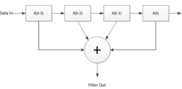
Fig. 2 shows a typical digital filter for small embedded system such as a digital wearable device [9], with the following expression:
Fig. 2. Block diagram of a typical filter.
그림 2. 전형적인 필터의 블록도.
(2)
This filter can be efficiently implemented using four registers by selecting 0.25 as α in Eq. (1). The following two figures show a signal from an accelerometer before and after filtering.
Fig. 3. Raw acceleration.
그림 3. 가공전 가속도.
Fig. 4. Filtered acceleration.
그림 4. 필터된 가속도.
By selecting an appropriate filter coefficient, electrical noise and spurious acceleration caused by unstable mounting of the wearable device will be effectively reduced. The filter coefficient α can be selected through repeated experiments.
2.2 Filter for detecting the vertical
The output from a three-axis MEMS sensor in a wearable devices will be affected by the wearer’s walking pattern [14]. In order to find the vertical, which will be used as the Z-axis for counting steps, the time is required for several steps. This is done using an acceleration along each axis is averaged filter coefficient of α 0.03 because the sampling period of each axis is 30mS and the time required for a step is almost 1S. This filter can be formulated as follow is.
(3)
The result of applying this filter is shown in Fig.
5. This averaging step eliminates the constant acceleration due to gravity from the x-axis and isolates the accelerations due to walking or running.
We can select a single threshold for determining the step-up and step-down transitions irrespective of the gradient being measured by the wearable devices wearer [14][15].
Fig. 5. Raw 3-axis acceleration.
그림. 가공전 3축 가속도.
Fig. 6. Filtered accelerations: the Z-axis is vertical.
그림 6. 필터된 가속도: Z축이 중력방향.
2.3 Axis rotation of X, Z plane
Accelerometer vector is rotated through X, Z, where
Where have been filtered using Eq. 3. The new accelerations are:
′ cos sin (4)
′ (5)
′ sin cos (6)
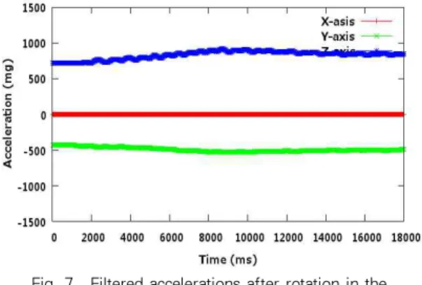
Figure 7 shows the effect of this rotation on the accelerations of Fig. 6.
Fig. 7. Filtered accelerations after rotation in the XZ-plane.
그림 7. XZ-plane으로 회전된 가속도.
In Fig. 7, the residual X-axis acceleration is eliminated by further rotation.
2.4 Rotation of Y, Z plane
To Consider the Y axis and Z axis, the X-axis and Z axis to rotate a vector is used because the element on Z axis has changed by the rotation. In other words, the angle between Y-axis element and Z-axis element is calculated as following equation:
tan ′
′
The vector rotation algorithm of this angle on the Z axis is followed
″′
″ cos′ sin ′
″ sin ′ cos′
The rotated X”, Y” and Z” in the direction Z are depicted in Fig. 8.
In Fig. 8, the acceleration of the Z would be increased as much as the amount of Z direction on X and Y while applying vector rotation, but the each accelerations of X component and Y component became zero by vector rotation to Z axis which are not affected by person’s walking nor running.
Fig. 8. Filtered accelerations after rotation in the YZ-plane.
그림 8. YZ-plane으로 회전된 가속도.
2.5 Counting steps from the vertical acceleration There are ways of detecting steps using accelerometers, which employ various filter such as differential, sliding window, and averaging [9][16].
We use the averaging method since it is the simplest and we have already collected the vertical. The transient acceleration along each axis can be calculated by subtracting the average acceleration obtained from Eq. 3 from the filtered raw accelerations from Eq. 1, resulting α to 0.25. This eliminates the constant acceleration due to gravity.
Fig. 9 shows the accelerations along each axis as a result of step of 2.4. As we expect, the Z-axis acceleration is dominant in steps of D. now be counted by counting zero crossing on the graph of vertical acceleration [8].
Fig. 9. Accelerations along each axis after the elimination of the acceleration due to gravity.
그림 9. 중력에 의한 가속도를 제거한 각 축의 가속도.
A step is counted if acceleration of without gravity exceeds a threshold. The Fig. 10 shows the acceleration in the vertical direction after each step of the GRVR algorithm. Fig. 11 shows how steps are counted.
Fig. 10. Comparison of acceleration of rotated z-axis of elimination of the acceleration due to gravity.
그림 10. 중력에 의한 가속도 제거 후, 가공전 Z축 가속도와 벡터 회전 후 가속도 비교.
Fig. 11. Step counting from the vertical acceleration without gravity.
그림 11. 중력에 의한 가속도 제거 후 걸음 수 측정.
III. EXPERIMENTAL RESULTS
We conducted several experiments for different wearable device mounting points in the middle of the wearer’s belt, on the right side of the belt and on the wrist. In each of these experiments, the step-count obtained by GRVR was compared with the count from a HJ-303 spring-lever pedometers, while the wearer walked at 3kph (~1.86mph). Most pedometers under-count steps by 50~90% at a speeds between 1.8 and 2.0mph [17][5]. A GRVR runs on an eZ430-Chronos which supports sub-1GHz RF communication with a PC. The eZ430-Chronos incorporates a VTI CMA3000 3-axis accelerometer [18], which measures accelerations in the range of +/-2g along each axis, with 8-bit resolution at 80Hz frequency [18]. The Z430-Chronos reads each axis acceleration every 30ms as requested by the PC. The eZ430-Chronos was configured to send data over the SimpliciTI protocol at 915MHz. The experimental configuration is depicted in Fig. 12.
Fig. 12. Communication our wearable device and the host.
그림 12. 웨어러블 디바이스와 호스트간의 통신.
The experiments were conducted in two steps:
The first step is to put the real-time acceleration data into a spread-sheet on the PC; and the second step is 3-axis acceleration values using GRVR.
Step-counting is then performed by the algorithm shown in step of 2.5.
Mounting position GRVR HJ-303 Runtastic
Avg. Min Max Avg. Min Max Avg. Min Max
Middle of belt 99.4 81 109 98.6 94 104 103.8 102 105
Right of belt 99.4 94 104 96 94 99 103 101 104
The wrist 106.8 101 116 83 66 101 54.6 53 59
In a back pack 101.6 192 115 97.6 84 117 99 98 100
Table 1. Step counts for 5 times of each mounting.(Unit: Steps) 표 1. 각각의 부착 위치에 다른 걸음 수 측정 비교.(단위: 걸음 수) When the wearable device is mounted in the
middle or on the right of the belt, as shown in Fig.
13 and 15, GRVR counts average 99.4 steps but the HJ-303 counts the average step of 98.4 / 96, and Runtastic counts the average step of 54.6 / 103 respectively which is shown in the Table 1. The Runtastic is a pedometer application in Android market. Nokia wrist-attached sensor platform, the step counter consistently acquired around 30% too few steps [6].
Fig. 13. Step count in the middle of the belt.
그림 13. 허리 벨트 중앙에 부착한 경우의 걸음 수 측정.
When the wearable device is mounted on the right of the belt, as depicted on Fig. 14, the acceleration values are lower right and left strides are usually not in identical. The step count obtained from the right of belt is shown in Fig. 15, but GRVR, only required one universal threshold for step counting wherever the wearable device is mounted, which benefits implementation in a small embedded system design with restricted resource for both computing power and memory.
Fig. 14. Wearable devices mounted on the right of the belt.
그림 14. 허리 벨트 우측에 부착된 웨어러블 디바이스.
Fig. 15. Acceleration determined by GRVR and count on the right of the belt.
그림 15. 허리 벨트 우측 부착이 경우 GRVR을 이용한 가속도 및 걸음 수.
Fig. 16. Wearable devices mounted on the wrist.
그림 16. 손목에 부착된 웨어러블 디바이스.
Fig. 17. Step count on wrist.
그림 17. 손목 부착의 경우 걸음 수.
Fig. 18. Wearable devices mounted in the backpack.
그림 18. Backpack에 에 부착된 웨어러블 디바이스.
We evaluated GRVR’s performance when the wearable device is mounted on the wrist, as shown in Fig. 16, or on a backpack, as shown in Fig. 18.
The GRVR algorithm is 99.4% accurate when the wearable device is mounted on the belt, and 91.1%
on the wrist and 98.4% on backpack. But, Fig. 17 shows that 52 steps were counted without GRVR and 98 steps with GRVR when human walked 100 steps.
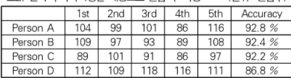
We have conducted another experiments for four people with wrist mounding to avoid dependence of a specific person’s step pattern. The following Table 2. shows 91.1% of accuracy from the four people's experimental by step counting using GRVR and Table 3. shows each people's height and weight for
the experiment of Table 2.
1st 2nd 3rd 4th 5th Accuracy Person A 104 99 101 86 116 92.8 % Person B 109 97 93 89 108 92.4 %
Person C 89 101 91 86 97 92.2 %
Person D 112 109 118 116 111 86.8 % Table 2. Step counts for four people with wrist
mounting.(Unit: Steps)
표2. 손목 부착의 4명을 대상으로 걸음 수 측정 (단위: 걸음수)
Height Weight
Person A 170cm 65 kg
Person B 178cm 61 kg
Person C 162cm 52 kg
Person D 121cm 26 kg
Table 3. Height and weight of each people 표3. 실험자의 키 및 몸무게
IV. CONCLUSION
We propose a gravity removal and vector rotation technique for counting steps. We evaluated the
GRVR algorithm with a low-cost
micro-electro-mechanical 3-axis accelerometer in a low-power embedded system while the wearable device is wore in various locations. The step count obtained from the right of belt is shown in Fig. 15, but GRVR, only required one universal threshold for step counting wherever the wearable device is mounted, which benefits implementation in a small embedded system design with restricted resource for both computing power and memory. By a vector rotation, the acceleration on the gravity axis is correctly measured even if the acceleration vector is distributed to gravity axis and other directions.
Furthermore, the threshold value for step counting can be fixed as one universal typical value regardless of where a wearable device is mounted.
These error rates will increase at walking speeds below 3km/h and running speeds below 10km/h [12]. In future work, we plan to evaluate GRVR algorithm at more speeds and evaluate other wearable device mounting points such as a pocket, shoe, or helmet. A low-pass filter eliminates the
constant acceleration due to gravity of the accelerations on the yaw, pitch, and roll axis. GRVR then counts step from the yaw-axis acceleration alone. Thus the count is not affected by the wearable device’s orientation. Experimental results show 99.4% accuracies between 91.1% and 99.4%
depending on mounting position.
참고문헌
[1] D. M. Bravata, C. S. Spangler, Using pedometers to increase physical activity and improve health, Journal of the American Medical Association, Vol. 298. No. 19, Nov. 2007.
[2] ACSM metabolic equations, http://blue.utb.edu /mbailey/handouts/pdf/MetCalnew.pdf
[3] Y. Kawahara, N. Ryu, T. Asami, Monitoring daily energy expenditure using 3-axis accelerometer with a low-power microprocessor, e-minds, Vol. 1, No. 5,2009(www.eminds.hci-rg.com).
[4] B. E. Ainsworth, W. L. Haskell, M. C. Whitt, M.
L. Irwin, A. M. Swartz, S. J. Strath, W. L.
O’Brien, D. R. Bassett, Jr, K. H. Schmitz, P. O.
Emplaincourt, D. R. Jacobs, Jr, and A. S. Leon, Compendium of physical activities: an update of activity codes and MET intensities, Medicine and Science in Sports and Exercise Vol. 32 S498-S516, 2000.
[5] E. L. Melanson, J. R. Troll, M. L. Bell, W. T.
Donahoo, J. O. Hill, L. J. Ynjje, L.
Lennigham-Foster, J. C. Beters, and J. S.
Levinre, Commercially available pedometers:
considerations for accurate step counting, PREVENTIVE MEDICINE Vol. 39, 2004.
[6] T.M. Ahola, Pedometer for running activity using accelerometer sensors on the wrist, MEDICAL EQUIPMENT INSIGHTS Vol. 3, 2010.
[7] A. L. G Meijer, K. R. Westerterp, F. M. H.
Verhoeven, H. B. M. Koper, and F. ten Hoor, Methods to assess physical activity with special reference to motion sensors and accelerometers, IEEE TRACTIONS OF ON BIOMEDICAL
ENGINEERING, Vol. 38, No. 3, Mar. 1991.
[8] J. W. Kim, H. J. Jang, D. H. Hwang, and C. S.
Park, A step, stride and heading determination for the pedestrian navigation system, JOURNAL OF GLOBAL POSITIONING SYSTEMS, Vol. 3, No. 1-2, pp273-279, 2004.
[9] N. Zhao, Full-featured pedometer design realized with 3-axis digital accelerometer, ANALOG DIALOGUE 44-06, June 2010.
[10] C. G. Ryan, P. M. Grant, W. W. Tigbe, and M.
H. Granat. Br J, The validity and reliability of a novel activity monitor as a measure of walking, British Journal of Sports Medicine, Vol. 40, pp. 779-784, 2006.
[11]Texas Instruments, eZ430-Chronos™ Development Tool User's Guide, Dec. 2010.
[12] A. R. Jimenez, F. Seco, C. Prieto, and J.
Guevara., A comparison of pedestrian dead-reckoning algorithms using a low-cost MEMS IMU, 6TH IEEE INTERNATIONAL SYMPOSIUM OF INTELLIGENT SIGNAL PROCESSING, WSIP 2009 26-28 August, 2009.
[13] A. Milenković, C. Otto, and E. Jovanov, Wireless sensor networks for personal health monitoring: issues and an Implementation.
[14] A. AKAHORI, Y. KISHIMOTO and K. Oguri, Estimate activity for M-health using one three-axis accelerometer, 3RD IEEE-EMBS, INTERNATIONAL SUMMER SCHOOL.
IEEE-EMBS, MIT, Sept. 4-6, 2006.
[15] P. L. Schneider, S. E. Crouter, O. Lukajic and D. R. Bassett, Jr, Accuracy and reliability of 10 pedometers for measuring steps over a 400-m walk, MEDICINE AND SCIENCE IN SPORTS AND EXERCISE, Vol. 3, No. 10, pp. 1779-84, Oct. 2003.
[16] S. Y. Cho, C. G. Park, and J. G. Lee, A personal navigation system using low-cost MEMS/GPS/Fluxgate, ION 59TH ANNUAL MEETING /CIGTF 22ND GUIDENCE TEST SYMPOSIUM, Albuquerque, NM , 23-25 June
2003.
[17] P. L. Schneider, S. E. Crouter, and D. R.
Basset, Jr, Pedometer measures of free-living physical activity: comparison of 13 Models, MEDICINE AND SCIENCE IN SPORTS AND EXERCISE, Vol. 36, No. 2, pp.331-5, 2004.
[18] CMA3000-D01 3-axis ultra low power accelerometer with digital SPI and I2C interface, VTI Technologies.
저 자 소 개 김 승 영 1998: 인하대학교
전기공학과 공학사.
2002: 인하대학교
컴퓨터정보공학과 공학석사.
현 재: 인하대학교
컴퓨터정보공학과 공학 박사과정 관심분야: 센서네트워크,
멀티홉 무선 센서 네트워크 Email : [email protected] 권 구 인
1995: 인하대학교 컴퓨터공학과 공학사.
1998: City University of NewYork 컴퓨터공학과 공학석사.
2005: Boston University Computer Science 공학박사,
현 재: 인하대학교
컴퓨터정보공학부 교수 관심분야: Software Defined Network,
센서네트워크 Email : [email protected]