Effect of Microstructure on Hydrogen Induced Cracking Resistance of High Strength Low Alloy Steels
Seong Ung Koh1,†, Hwan Gyo Jung2, and Kyoo Young Kim3
1,3Dept. of Mat. Sci. and Tech., Pohang Univ. of Sci. and Tech., Korea
2Technical Research Center, Pohang Iron & Steel Co., Ltd., Korea
Hydrogen induced cracking (HIC) was studied phenomenologically and the effect of microstructure on HIC was discussed for the steels having two different levels of nonmetallic inclusions. Steels having different microstructures were produced by thermomechanically controlled processes (TMCP) from two different heats which had the different level of nonmetallic inclusions. Ferrite/pearlite (F/P), ferrite/acicular ferrite (F/AF), ferrite/bainite (F/B) were three representative microstructures for all tested steels. For the steels with higher level of inclusions, permissible inclusion level for HIC not to develop was different according to steelmicrostructure. On the contrary, HIC occurred also at the martensite/austenite (M/A) constituents regardless of steel microstructure when they accumulated to a certain degree. It was proved that M/A constituents were easily embrittled by hydrogen atoms. Steels having F/AF is resistant to HIC at a given actual service condition since they covers a wide range of diffusible hydrogen content without developing HIC.
Keywords : HIC, microstructure, inclusion, M/A constituent, hydrogen diffusion.
†Corresponding author: [email protected]
1. Introduction
As the requirement for linepipe steel products with higher strength and toughness is increased to improve the oil/gas transportation efficiency, investigation about the effects of steel microstructure on the susceptibility to HIC becomes of great importance. Coarse bands of F/P in hot rolled low carbon steels are sensitive to hydrogen induced blister cracking (HIBC) along pearlite bands parallel to the rolling direction.1) In addition, formation of hard phases such as M/A constituents and bainite also increases HIC suscepti- bility of steels according to their fraction and distribution in steel matrix.2),3) Hence, the effect of microstructure on hydrogen degradation is very complex and must be consid- ered to achieve maximum resistance to HIC. In general, HIC resistance decreases as the strength of steel or defect density in steel increases. Therefore, it is expected that critical hydrogen content for developing HIC decreases as the strength of steels or defect density in steel increases because hard matrix or steels with high defect density is sensitive to brittle cracking.
In this study, the effect of steel microstructure on HIC is discussed with respect to steel microstructure and in- clusion level. Effect of inclusion level on HIC according
to surrounding microstructure was studied by comparing the steels with different amount of inclusions while having the identical microstructure. Detailed study on the effect of steel microstructure on HIC was made in the condition that the effect of inclusion could be excluded; steels with different microstructure were investigated while inclusion level was identical in low level. Interaction between hydro- gen diffusion and steel microstructure is also taken into careful consideration.
2. Experimental procedure
The materials used in this study were 20 mm thick steel plates produced by using laboratory scale pilot rolling plant. Two kinds of steel heats (Heats S and SF) having almost identical chemical composition were control-rolled to produce different kinds of microstructures such as F, F/AF and F/B. Two different steel heats were used to eval- uate the role of inclusions on HIC since inclusion level in different steel heats is apt to be different and their level is hard to artificially control. The chemical composition of tested steels is listed in Table 1. By controlling the cooling condition, nine steel plates from each heat were produced.
Table 1. Chemical composition of test materials (wt%)
C Mn Si P+S Al Nb+Ti+V Cu+Ni Ca Cr Mo
~0.05 1.25 0.2 >0.05 ~0.1 ~0.1 ~0.4 >0.002 ~0.1 ~0.1
(a) (b) (c)
Fig. 1. Typical OM microstructures for the steels produced from Heats S and SF: (a) ferrite/pearlite, (b) ferrite/acicular ferrite and (c) ferrite/bainite.
For the microstructural analysis, mirror polished speci- mens were etched with various etching techniques includ- ing tint etching method and the primary microstructure for each steel plate was defined. Distribution of inclusions in two steel heats was evaluated at t/8 position, where t was the thickness of steel plates, since HIC frequently occurs at this position. To clearly understand the effect of microstructure on HIC when inclusions are not consid- ered, microstructural details such as fraction of hard secon- dary phases were analyzed for the steels produced from Heat S.
To evaluate HIC susceptibility of steels, the value of crack area ratio (CAR) at t/8 position was measured fol- lowed by standard HIC test in reference to NACE TM0284-96A.4) After HIC testing, HIC surfaces were re- vealed and fracturing behavior was investigated by OM, SEM and energy disperse spectroscopy (EDS).
The amount of hydrogen in steels is one of the most important parameters to determine the resistance of steels to HIC since HIC occurs due to hydrogen. The amount of diffusible hydrogen after 96hrs’ exposure to NACE TM01-77A solution was measured using a modified glyc- erin method5).
3. Result and discussion
3.1 Microstructure
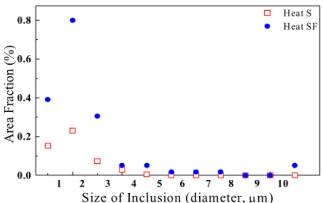
Typical microstructures of tested steels are shown in Fig. 1. Fig. 2 shows the distribution of nonmetallic in- clusions for Heats S and SF. Heat SF has larger amount
of nonmetallic inclusions than Heat S. Total amount of nonmetallic inclusions is 0.49 area % for Heat S and 1.7 area % for Heat SF, respectively. Larger amount of non- metallic inclusions in Heat SF may leads to inclusion clus- tering during hot rolling and increase the chance to develop HIC at nonmetallic inclusions.
Fraction of M/A constituents was measured by using tint etching method.6) In Fig. 3, representative micro- structure of Steel S1~S9 and the fraction of M/A con- stituents in them are summarized.
0.0 0.2 0.4 0.6 0.8
1 2 3 4 5 6 7 8 9 10 Heat S Heat SF
Area Fraction (%)
Size of Inclusion (diameter, μm)
Fig. 2. Distribution of nonmetallic inclusions for Heats S and SF.
S1 (F/P) 0.94 S4 (F/P) 1.28 S7 (F/P) 0.88 S2 (F/AP) 1.40 S5 (F/AP) 2.86 S8 (F/BF) 1.21 S3 (F/AP) 3.64 S6 (F/AP) 5.73 S9 (F/BF) 4.45 Fig. 3. Steel microstructure and M/A fraction in them (Heat S).
(a) (b) (c) (d)
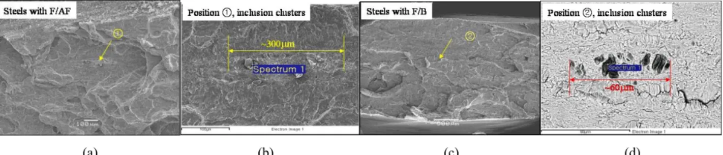
Fig. 5. HIC nucleation sites for the steels produced from Heat SF: (a), (b) ferrite/acicular microstructure, (c) and (d) ferrite/bainite microstructure.
(a) (b) (c) (d)
Fig. 6. HIC nucleation sites for the steels produced from Heat S: (a) macroscopic view of fracture surface, (b), (c) crack nucleation sites (position 1 in (a)), and (d) quasi‐cleavage crack propagation (position 2 in (a)).
3.2 HIC resistance and fracture analysis
The effect of microstructure on HIC is discussed with respect to inclusion level and detailed microstructure.
Among all tested steels, steels with F microstructure did not develop HIC at a given experimental condition and defect level as shown in Fig. 4. HIC susceptibility (CAR) is higher for the steels produced from Heat SF for an iden- tical microstructure. HIC dependence on inclusions is higher for the steels having hard microstructure, bainite.
As the microstructure changes from ferrite or AF to B, CAR value increases for all steels and HIC is strongly affected by microstructure when inclusion level is high, i.e. steels produced from Heat SF. This not only indicates that HIC can be effectively decreased when the number of nonmetallic inclusions is reduced but also informs that interaction between defect sites and surrounding micro- structure for HIC nucleation must exist. Steels produced from Heat S, which have the lower inclusion level, also develop HIC when the microstructure of steels is F/AF or F/B even though CAR value is quite small. HIC resist- ance of ferrite microstructure according to the change in inclusion level could not be explained since steels with ferrite microstructure was observed only in steels produced from Heat S which had the lower inclusion level. From Fig. 4, it can be also emphasized that HIC can be effec- tively reduced when the microstructure is controlled from
F/B into AF even for the steels having high inclusion level.
Change in microstructure from F/B into AF can also meet the requirement on high strength and toughness along with high sour resistance.7)-10)
After HIC testing, HIC fracture surfaces were observed as shown in Figs. 5 and 6. For the steels produced from Heat SF, HIC nucleated at nonmetallic inclusion clusters.
Whereas, for the steels produced from Heat S, HIC nucleated at abnormal MA clusters. However, CAR value for these steels is below 1% due to low inclusion level.
Higher CAR value for the steels produced from Heat SF in Fig. 5 is due to the higher level of inclusion. For these steels, CAR value in F/AF is lower than that in F/B. This
-2 0 2 4 6 8 10 12 14 16
F/AF F/B F
H eat S H eat S F
Crack Area Ratio (CAR, %)
Steel M icrostructure
Fig. 4. Effect of inclusion level and microstructure on HIC.
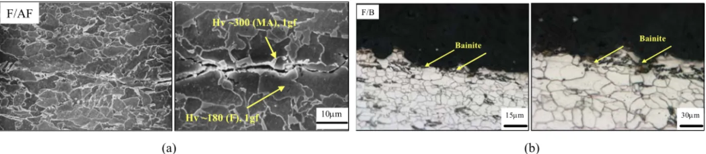
10μm Hv ~300 (MA), 1gf
Hv ~180 (F), 1gf F/AF
15μm 30μm
F/B
Bainite Bainite
(a) (b)
Fig. 7. HIC propagation in steels with (a) ferrite/acicular ferrite and (b) ferrite/bainite.
was proved from the observation on fracture surfaces; in- clusion clusters over 20 μm in diameter were activated as HIC nucleation sites in F/B while was not activated in F/AF. In addition, HIC occurred in steels with F/AF microstructure only when inclusion cluster size in diameter was over 150 μm. This implies that AF is more resistant to HIC than bainite regardless of inclusion level since CAR value in steels produced from Heat S also was higher in F/B.
Once HIC nucleates, it propagates along the hard phases no matter where HIC nucleates. For the steels having F/AF, HIC propagates along M/A constituents while HIC propagates along bainites when the microstructure is F/B as shown in Fig. 7.
Study on the effect of steel microstructure on HIC was made in detail with the steels produced from Heat S, which had lower level of nonmetallic inclusions, since HIC did not develop at nonmetallic inclusions in these steels (Steels S1-S9).
Change in microstructure including the formation and distribution of second phases plays important roles in de- termining HIC resistance of linepipe steels. If M/A con- stituents are detrimental to HIC, Steels S3, S6 and S9 will be sensitive to HIC.11) However, the distribution of M/A is considered to be more important since its size is too small to act as independent crack nucleation site; the size of an M/A constituent in tested steel is about 2 μm in diameter. Fraction of M/A constituents and CAR value for Steels S1~S9 are summarized in Table 2. HIC occurred in Steels S6, S8 and S9. Even though fraction of M/A constituents is high enough to develop HIC in Steel S3 compared to Steel S8 because M/A constituents are detri- mental HIC nucleation sites as shown in Fig. 6, Steel S3 did not experience HIC at a given experimental condition.
Detailed observation on fracture surfaces, however, made it possible to explain this phenomenon. As shown in Fig.
6, M/A constituents agglomerate at the HIC nucleation site and this is much larger amount when average area fraction of them is considered. This implies that HIC nu- cleation site is more critically related to the local enrich-
Table 2. M/A fraction and CAR for the steels produced from Heat S.
Steel S1 S2 S3 S4 S5 S6 S7 S8 S9
%MA 0.94 1.4 3.64 1.28 2.86 5.73 0.88 1.21 4.45
%CAR 0 0 0 0 0 0.05 0 0.17 0.57
ment of M/A agglomerates rather than the average dis- tribution of M/A constituents. Intensive observation on fracture surfaces led to the conclusion that M/A clusters with 100 μm in length and 20 area % localized along the transverse direction to rolling plane could cause HIC. M/A constituents in F/B microstructure are likely to agglomer- ate during accelerated cooling since carbon enriched prior austenite in ferrite/austenite two-phase region may result in the agglomeration of hard phases. Nevertheless, it is also important that average fraction of M/A constituents in steels could be the screening parameter over which HIC possibly occurs.
3.3 Effect of hydrogen content on HIC
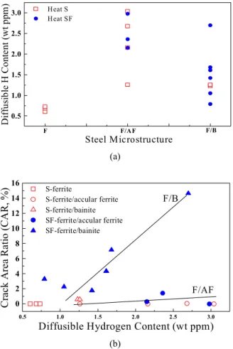
Diffusion of hydrogen is one of the most important pa- rameters to affect HIC because HIC is induced by in- gression of hydrogen in the steel. HIC susceptibility of steels is often explained in terms of diffusible hydrogen content in steels, since diffusible hydrogen embrittles mi- crostructure surrounding the potential HIC sites.12) Fig.
8(a) shows the diffusible hydrogen content in all tested steels directly measured after HIC testing. As is noted from this figure, there is no direct relationship between primary microstructure of steels and diffusible hydrogen content; even for the steels having F/B microstructure, wide range of diffusible hydrogen content is observed.
And, inclusion level in steels does not affect diffusible hydrogen content as well when comparing steels produced from different heats having different level of inclusion as shown in Fig. 8(a). Diffusible hydrogen content in steels accounts for the solubility of hydrogen atoms in steels.
Hydrogen solubility in steels is closely related with rever- sible hydrogen trapping sites such as solute atoms and
0.5 1.0 1.5 2.0 2.5 3.0
Steel Microstructure
Heat S Heat SF
F/AF F/B F
Diffusible H Content (wt ppm)
(a)
0.5 1.0 1.5 2.0 2.5 3.0
0 2 4 6 8 10 12 14
16 S-ferrite
S-ferrite/accular ferrite S-ferrite/bainite SF-ferrite/accular ferrite SF-ferrite/bainite
Crack Area Ratio (CAR, %)
Diffusible Hydrogen Content (wt ppm) F/AF F/B
(b)
Fig. 8. Relationship between (a) steel microstructure and diffusible hydrogen content and (b) diffusible hydrogen content and HIC susceptibility.
dislocations.13),14) Cold working decreases the hydrogen diffusivity and increases the hydrogen solubility in steels.15),16) From this view point, wide range of dislocation density in AF and bainite seems to account for wide range of diffusible hydrogen content. However, a systematic study on the relationship between diffusible hydrogen con- tent and metallurgical parameters is required.
Fig. 8(b) represents the effect of diffusible hydrogen content on HIC of tested steels according to steel micro- structure and type of steel heat (inclusion level). It can be seen from this figure that HIC does not occur in F/AF microstructure, or HIC level is very low in F/AF micro- structure, along the wide range of diffusible hydrogen content. This indicates that AF microstructure is resistant to HIC since CAR value for steels having F/AF micro- structure is below 2% even when inclusion level is high (Heat SF) and diffusible hydrogen content is over 3 ppm.
On the other hand, CAR value for steels having F/B micro- structure almost proportionally increases as diffusible hy- drogen content increases, implying that bainite micro-
structure is prone to HIC by diffusible hydrogen. As for F/P microstructure, relationship between diffusible hydro- gen content and HIC cannot be explained because diffu- sible hydrogen content of all tested steels having ferrite microstructure is below 1 ppm and HIC does not occur.
Considering all parameters determining the soundness of linepipe steels, i.e. strength, toughness and HIC resist- ance, steels having AF microstructure with low inclusion level and evenly distributed M/A constituents is recom- mended.
4. Summary
HIC resistance decreases as the inclusion level increases when the microstructure is identical, and permissible in- clusion level is quite dependent on surrounding micro- structure; critical inclusion cluster size for HIC nucleation is about 150 μm in diameter for F/AF, while 20 μm for F/B.
Even when inclusion level is low enough for HIC not to occur at inclusions, clustering of M/A constituents may induce HIC regardless of steel microstructure when they are agglomerated to a certain degree; 100 μm in length and 20 area % localized along the transverse direction to rolling plane.
AF microstructure is the most resistant to HIC among all tested microstructures. It covers a wide range of diffu- sible hydrogen contents without HIC or with small amount of HIC. This means that F/AF microstructure is not se- verely embrittled even when diffusible hydrogen content is high. On the other hand, HIC susceptibility of F/B mi- crostructure is almost proportional to diffusible hydrogen content. This indicates that F/B microstructure is apt to be embrittled by diffusible hydrogen.
References
1. G. Irzov, Fiz. Khim. Mekh. Mat., 18, 89 (1982).
2. C. M. Liao and J. L. Lee, Corrosion, 50, 695 (1994).
3. H. Y. Liou, C. M. Liao, Chinese Jouranl of Materials Science, 23, 124 (1990).
4. “Evaluation of Pipeline and Pressure Vessel Steels for Resistance to Hydrogen Induced Cracking”, NACE standard TM0284-96 (Houston, TX: NACE Internatio- nal, 1996)
5. C. Shutt and D. A. Fink, Welding Journal, 19 (1985).
6. K. D. Amar, J. G. Speer, D. K. Matlock, Advanced Materials and Process, 27 (2003).
7. P. J. Hurley, G. L. Kelly, P. D. Hudson, Materials Science and Technology, 16, 273 (2000).
8. R. Priestner, L. Ali, Materials Science and Technology, 9, 135 (1993).
9. M. C. Zhao, Y. Y. Shan, F. R. Xiao, K. Yang, Y. H.
Li, Materials Letters, 57, 145 (2002).
10. J. C. Charbonnier, H. M. Marette, A. M. Brass, M.
Aucouturier, Metallurgical Transactions, 16A, 935 (1985).
11. “Sulfide stress cracking resistant metallic materials for oil field equipment”, NACE standard MR0175 (Houston, TX: NACE International, 2002)
12. T. Hara, H. Asahi, H. Ogawa, Corrosion, 60, 1113 (2004).
13. G. M. Pressouyre, I. M. Bernstein, Metallurgical Transactions, 9A, 1571 (1978).
14. R. Gibala, A. J. Kumnick, “Hydrogen embrittlement and Stress corrosion cracking”, 61 (1985).
15. M. Uhlemann, H. J. Engelmann, K. Mummert, Werkstoffe and Korrosion, 46, 63 (1995).
16. T. K. G, Namboodhiri, Trans. Soc. Adv. Electrochem.
Sci. Technol., 13, 77 (1978).