This work was supported by Korea Science and Engineering Foundation (KOSEF) grant funded by the Korea government (MEST;
No. 2009-0078361, No.2010-0003315) and National Cancer Center of Korea.
Submitted August 13, 2010, Accepted October 20, 2010
Corresponding Author: Tae-Suk Suh, Department of Biomedical Engineering, The Catholic University of Korea, 505, Banpo-dong, Seocho-gu, Seoul 137-701, Korea.
Tel: 02-2258-7232, Fax: 02-2258-7506 E-mail: [email protected]
Evaluation of the Secondary Particle Effect in Inhomogeneous Media for Proton Therapy Using Geant4 Based MC Simulation
So-Hyun Park*, Won-Gyun Jung*, Jeong-Eun Rah†, Sungyong Park†, Tae-Suk Suh*
*Department of Biomedical Engineering, Catholic University of Korea,
†Proton Therapy Center, National Cancer Center of Korea, Seoul, Korea
In proton therapy, the analysis of secondary particles is important due to delivered dose outside the target volume and thus increased potential risk for the development of secondary cancer. The purpose of this study is to analyze the influence of secondary particles from proton beams on fluence and energy deposition in the presence of inhomogeneous material by using Geant4 simulation toolkit. The inhomogeneity was modeled with the condition that the adipose tissue, bone and lung equivalent slab with thickness of 2 cm were inserted at 30% (Plateau region) and 80% (Bragg peak region) dose points of maximum dose in Bragg curve. The energy of proton was varied with 100, 130, 160 and 190 MeV for energy dependency. The results for secondary particles were presented for the fluence and deposited energy of secondary particles at inhomogeneous condition. Our study demonstrates that the fluence of secondary particles is neither influenced insertion of inhomogeneties nor the energy of initial proton, while there is a little effect by material density. The deposited energy of secondary particles has a difference in the position placed inhomogeneous materials. In the Plateau region, deposited energy of secondary particles mostly depends on the density of inserted materials. Deposited energy in the Bragg region, in otherwise, is influenced by both density of inserted material and initial energy of proton beams. Our results suggest a possibility of prediction about the distribution of secondary particles within complex heterogeneity.
Key Words: Secondary particles, Inhomogeneity, Geant4, Fluence, Energy
INTRODUCTION
In radiation therapy, one of the most important points is to concentrate a uniform prescribed dose into the target volume while minimizing irradiation to surrounding normal tissue.
High energy proton beam is one of those techniques that de- liver a highly conformal dose with sharp lateral and distal fall-off penumbra. However, uniform dose distribution of pro- ton beams is affected by Multiple Coulomb Scatterings (MCS) between proton beams and materials located in the traveling path of protons.
Through MCS in materials, protons are slowed down with losing their kinetic energy, mainly by inducing ionization of the medium atoms which produces secondary electrons with the average deposit energy of less than 10 keV into the sur- rounding materials.1) Although the energy deposited directly by the proton represents total energy deposited along the track, the relative contribution of these secondary electrons becomes larger for increasing energy of the projectile when an energy threshold is adopted.2) Furthermore, MCS cause different beam composition in energy and direction of proton because of the statistical character of the energy deposition by proton beams which can be described by the particle’s stopping power and Gaussian distribution. It may entail different energy-loss rela- tionships, different degrees of scattering and range straggling of particles.3) In addition other secondary particles such as neutron and secondary proton et al affect the uniform dose in the medium.
Proton beams pass through complex geometrical structures of accelerator and then penetrate anatomical structures of patient. When the inhomogeneous structures are small or very
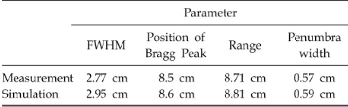
Fig. 1. Comparison results of measurement and simulation data for 108.8 MeV proton beams in the water phantom. Data are normalized to the dose of Bragg Peak.
Table 1. Comparison of parameters between measured and simulated Bragg curve.
Parameter
FWHM Position of
Bragg Peak Range Penumbra width Measurement 2.77 cm 8.5 cm 8.71 cm 0.57 cm Simulation 2.95 cm 8.6 cm 8.81 cm 0.59 cm different in chemical composition than the surrounding envi-
ronment, distribution of proton beam will be affected accordin- gly. In the clinical application, it is important to predict a dose perturbation due to the inhomogeneous structures or complex anatomical structures. It may induce cold or hot dose spot within the clinical target volume. These phenomena are also concerned with arising of secondary particles by proton beams.
In the proton therapy, prediction of secondary particles are of interest as they may deliver the dose outside the target volume or increase a potential risk of the development of radiation-in- duced cancer.4)
In this study, we discuss the influence of inhomogeneous materials on the creation of secondary particle in the traveling path of protons by using the Geant4 (Geometry And Tracking) simulation.
MATERIALS AND METHODS
1. Homogenous water phantom simulation
The Monte Carlo simulations in this study were carried out using Geant4 code (version 4.9.p02), a general-purpose radia- tion-transport-simulation code capable of simulating proton beams. This code requires essential files that define the in- formation concerning the particle, geometry and physics.
The phantom was placed in air and the geometry for the homogenous condition was set with water phantom (density ρ
=1.00 gcm−3). Its dimensions were modeled 40×10×10 cm.
The x-dimension was chosen as beam axis and the proton source was located 10 cm away from the upper surface of the water phantom.
5×10⁶ proton particles are generated for the simulation. All secondary particles of proton beams were subjected to be tracked if their ranges are longer than the defined cut-off threshold of 1.0 mm, including photon, electron and charged particles produced by primary proton beams.
For the reliability of simulation, simulated proton beams and measured beam data were compared. Proton beams for meas- urement were delivered at the National Cancer Center (NCC).
In the water phantom, spatial distribution of proton beams was described by Gaussian distributions. Proton beam with standard deviation of 2.4 MeV was adopted from repetitive comparing between measurement and simulation data. Measurement data
was acquired from Markus (PTW, Germany) ionization cham- ber in the water phantom for proton beam with 108.8 MeV.
The depth dose distribution from simulation was compared with that of measurement for a full-width at half-maximum (FWHM) value, position of Bragg peak, range and penumbra width. The FWHM were calculated as the distance between proximal and distal 50% dose location of maximum dose. The position of Bragg peak and range was determined as maximum dose point and distal 80% dose point of maximum dose in Bragg curve, respectively. The penumbra width was calculated the distance between the point of distal 80% dose and in of the distal 30% dose.
Physics models consist of electromagnetic and nuclear process. The electro-magnetic physics mainly conducts the cal- culation of the ionization and multiple-scattering process in each atom of the water phantom. The electro-magnetic model based on ICRU49 was applied for the low energy processes, down to 250 eV for photons and electrons as well as for ha- drons and ions.
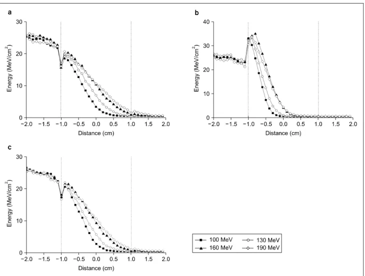
Fig. 2. Fluence of secondary particles in the presence of inhomogeneous material placed in the Plateau region with respect to the energy of initial proton beam of (a) 100 MeV, (b) 130 MeV (c) 160 MeV and (d) 190 MeV. Dot lines denote interface between water and inhomogeneous material. The values in the figure show the fluence of secondary particles at interface.
G4Precompound model was chosen as physics model of nu- clear process. This model was considered appropriate for this study, as it was suited to the therapeutic energy range that was to be simulated.5,6) In addition, the G4PreCompound model would account for the production of secondary particles as a result of inelastic reactions, including charged secondary par- ticles, neutrons and photons.
2. The simulation in inhomogeneous condition The inserted location of each heterogeneous material were selected in the region of Plateau and Bragg peak within Bragg curve, at the proximal 30% and 80% dose point of the max-
imum dose, respectively. These points were chosen from the pattern of depth dose distribution of the proton beams with the energy range between 100 and 190 MeV. For the study on the generation of secondary particles, the energy of proton beams was changed from 100 to 190 MeV with an increment of 30 MeV.
For the setup of heterogeneity condition, the slab geometry is applied in order to simplify the heterogeneous structures in our study. If inhomogeneous material is small, protons entering into inhomogeneous material laterally from surrounding me- dium are treated as if they were still moving in inhomoge- neous material and accounted for the interaction.7) Therefore,
Fig. 3. Energy distribution of secondary particles in the presence of inhomogeneous material placed in the Plateau region with respect to the energy of initial proton beam of (a) 100 MeV, (b) 130 MeV (c) 160 MeV and (d) 190 MeV. Dot lines denote interface between water and inhomogeneous material. The values in the figure show the energy deposited by secondary particles at interface.
slab width, the vertical direction of penetration axis of proton, was set up same size in the water phantom.
The density heterogeneities were set by inserting inhomoge- neous materials with thickness of 2.0 cm at each position within the water phantom. Heterogeneous materials were adipose tis- sue (density ρ=0.92 gcm−3), bone (density ρ=1.85 gcm−3) and lung (density ρ=1.05 gcm−3) equivalent slab.
The same physics models were applied as homogeneous condition, i.e., electro-magnetic physics based on ICRU49 and nuclear physics from theory-driven G4PreCompound model.
RESULTS
The results of comparison between simulation and measure- ment data for the proton beams in the homogeneous phantom are shown in the Fig. 1. The dose distributions were normal- ized with respect to the point of Bragg peak. There were good agreements for FWHM value, position of Bragg peak, range and penumbra width. Each data obtained from the simulation presents a slight shift compared to the measurement data.
Table 1 shows data of each parameter from measurement and
Fig. 4. Fluence of secondary particles in the presence of inhomogeneous material placed in the Bragg peak region with respect to the energy of initial proton beam of (a) 100 MeV, (b) 130 MeV (c) 160 MeV and (d) 190 MeV. Dot lines denote interface between water and inhomogeneous material. The values in the figure show the fluence of secondary particles at interface.
simulation. The differences are 1.8, 1, 1 and 0.2 mm, respec- tively. The dose differences in entrance region of Bragg curve are caused by the creation of secondary particles, where simu- lated data includes secondary particles produced by nonelastic nuclear reactions whereas measured data does not.
Results for secondary particle are shown as 1 cm water re- gions upstream and downstream from the interface as well as within inhomogeneous material.
Fig. 2, 3 show fluence and deposited energy of secondary particles, when inhomogeneous materials are inserted in Plateau region. Each graph demonstrates that patterns of secon- dary particles are slightly influenced by density material for
initial proton energy of 100, 130, 160 and 190 MeV. Area covered between two dot lines in graphs indicates the in- homogeneous material in the water phantom. The values at in- terfaces are fluence and energy values of secondary particles for each material. As seen in Fig. 2, fluence decrease has sim- ilar patterns for each inhomogeneous material with slight perturbations. The small perturbations of fluence have differ- ences less than 0.2% compared with those of secondary par- ticles in homogeneous condition in water and there are not many differences among adipose, bone and lung equivalent material.
Fig. 3 shows results of deposited energy of secondary par-
Fig. 5. Energy distribution of secondary particles in the presence of inhomogeneous material placed in the Bragg peak region with respect to the energy of initial proton beam of (a) 100 MeV, (b) 130 MeV (c) 160 MeV and (d) 190 MeV. Dot lines denote interface between water and inhomogeneous material. The values in the figure show the energy deposited by secondary particles at interface.
ticles. In the bone equivalent slab, energy deposition increases about 2 times compared with adipose tissue and lung equiv- alent slab. As the proton energy increase, energy deposition in- creases accordingly at the upstream interface, and decrease ten- dency inside the inhomogeneous material gets even for higher proton energy. For adipose and lung tissue, energy deposition decreases at both upstream and downstream interfaces and re- covers soon at the homogeneous level.
For the inhomogeneous material inserted in Bragg peak re- gion, fluence for each material presents similar pattern to that in Plateau region as shown in Fig. 4, while the results for the energy deposition look quite different from those in Plateau re-
gion as shown in the Fig. 5. For bone equivalent slab is placed, energy deposition of secondary particles rapidly decreases at a quarter point of bone thickness after quick rising in entrance region of bone slab. On the other hand, energy depositions in adipose tissue and lunge equivalent slab are slowly decreased compared with that of bone equivalent slab and the decrease upstream of adipose tissue and lunge surface was shown.
Energy dependency of the fluence and deposited energy of secondary particles is shown for each inhomogeneous material inserted in Plateau (Fig. 6, 7) and Bragg peak regions (Fig. 8, 9).
As the proton energy increase, there is no noticeable change of fluence at both boundaries for every kind of inhomogeneity,
Fig. 6. Energy dependency of fluence of secondary particles with respect to the density of inhomogeneous material placed in Plateau region of (a) adipose tissue (density ρ=0.92 gcm−3), (b) bone (density ρ=1.85 gcm−3) and (c) lung (density ρ= 1.05 gcm−3). Dot lines denote interface between water and inhomogeneous material. The values in the figure show the fluence of secondary particles at interface.
no matter where the inserts are located. For energy deposition, however, higher density of bone has the clear influence on it at both boundaries for the insertion in the region of Plateau, and at upstream boundary for the one in the region of Bragg peak. For every kind of inhomogeneity, energy deposition in- creases proportionally as the proton energy goes higher at both insertion locations. It should be noted that the range gets shorten quite much for bone slab insertion at Bragg peak re- gion comparing to other low density slabs showing gradual stopping of proton beam according to their initial energies.
DISCUSSION AND CONCLUSION
Our results show that inhomogeneity is an important influ- encing parameter to the fluence and deposited energy of sec- ondary particles by therapeutic proton beams. Although there are not clear solutions concerned with the pattern analysis of secondary particles produced by proton beams, some study by Paganetti on the distribution patterns of secondary particles may be a good guide to identify the phenomenon of secondary particles within inhomogeneous condition.8)
Urie et al demonstrated that the Bragg peak region is de-
Fig. 7. Energy dependency of energy deposition of secondary particles with respect to the density of inhomogeneous material placed in Plateau region of (a) adipose tissue (density ρ=0.92 gcm−3), (b) bone (density ρ=1.85 gcm−3) and (c) lung (density ρ=1.05 gcm−3).
Dot lines denote between water and inhomogeneous material. The values in the figure show the energy deposited by secondary particles at interface.
graded, causing substantial changes in the energy spectrum of the proton beam and thus in the distal fall-off width, when density heterogeneities are located in the proton beam’s path.
They also suggested that MCS (Multiple Coulomb Scattering) occurring at the interfaces of different materials influences to Bragg peak degradation.9,10) The interaction of MCS markedly affects the dose distributions of charged particles, when in- homogeneous material is existed. If MCS did not occur, they would simply shift the depths of the dose distributions by a distance equal to the area density of the material. However, MCS cannot be disregarded in clinical situations because hu- man body has complex structures with density differences.
In our results, effects of MCS are definitely identified at the interface regions. For the energy deposition of secondary par- ticles, there were degradations upstream and downstream of in- homogeneous material surface. The perturbation at interface by MCS effects is mainly caused by low energy of secondary particles because secondary electrons with low energy espe- cially cause bremsstrahlung or characteristic photon production in the interface between two different materials.11) As seen in Fig. 3, 5, increase of energy deposition is shown due to back- scattering effects by bone equivalent material in the upstream region of interface. For adipose and lung equivalent slab, de- creases of energy deposition are shown because there are not
Fig. 8. Energy dependency of fluence of secondary particles with respect to the density of inhomogeneous material placed in Bragg peak region of (a) adipose tissue (density ρ=0.92 gcm−3), (b) bone (density ρ=1.85 gcm−3) and (c) lung (density ρ=1.05 gcm−3).
Dot lines denote interface between water and inhomogeneous material. The values in the figure show the fluence of secondary particles at interface.
lots of density differences and there not exist enough equiv- alent electrons at the interface of water and materials.
As shown in Fig. 3, Decreasing tendency of energy deposi- tion in downstream side of Plateau region may be explained from the fact that low energy electrons are produced in in- homogeneous materials but do not have enough energy to con- tribute to the energy deposition into the water.
When inhomogeneous material is located in Bragg peak re- gion, bone equivalent slab affect change about rising region of Bragg peak. It comes with rapid decrease of deposited energy of secondary particles compared to adipose tissue and lung, re- sulting from quick reduction about the range of proton beams
in the high density of bone equivalent layer. In addition, the decrease on energy deposition of secondary particles occurs before initial proton beams stop, mostly just after upstream in- terface unlike the insertion in Plateau region. Therefore, this localization of energy deposition around upstream interface leads to the very short range of proton beams in bone equiv- alent layer as shown in Fig. 5. For reference, the proton beams with 100, 130, 160 and 190 MeV have range of 7.6, 9.4, 13.9 and 20 g/cm2, respectively.12)
Deposited energy is proportional to the stopping power of proton beams in heterogeneous region regardless of the energy of proton. For the adipose tissue, bone and lung, the stopping
Fig. 9. Energy dependency of energy deposition of secondary particles with respect to the density of inhomogeneous material placed in Bragg peak region of (a) adipose tissue (density ρ=0.92 gcm−3), (b) bone (density ρ=1.85 gcm−3) and (c) lung (density ρ=1.05 gcm−3). Dot lines denote interface between water and inhomogeneous material. The values in the figure show the energy deposited by secondary particles at interface.
power of proton beam has the stopping power of 0.95, 1.72 and 1.03, respectively.13)
As shown in Fig. 2 and 4, the fluence of secondary particles has similar values for adipose tissue, bone and lung equivalent slab, while the difference of energy deposition is definitely de- pending on the material density as discussed above. Goitein revealed that insertion of heterogeneous material does not cause a large proton fluence perturbation, but can create a sig- nificant dose perturbation of the secondary particles.14) The re- sults of our study demonstrated similarly to Goitein's results that fluence of secondary particles does not definitely depend on the inhomogeneous materials. The energy deposition, how-
ever, is influenced by the change of energy spectrum of secon- dary particles because average energy of secondary particles is shifted by inhomogeneous materials, which causes dose pertur- bation by secondary particles.
Results of figure 6 to 9 show pattern of energy dependence of secondary particles on initial proton energy for each identi- cal material, of adipose tissue, bone and lung. Similar patterns are demonstrated, when results are compared according to the material density. In our study on inhomogeneity, fluence and energy of secondary particles have difference less than 0.3%
compared with homogeneous condition in water.
Our study demonstrated that perturbation of secondary par-
ticles at interface of inhomogeneous material is mainly influ- enced by density differences of inhomogeneous material and energy of initial proton beams.
Proton beams offers a distal dose conformity that can pro- vide full coverage of the target volume and at the same time spare entirely the normal tissues behind. This unique dose dis- tribution is, however, very sensitive to inhomogeneities existed in beam path and thus influences on producing secondary particles. Although the secondary particles produced by proton beams have absorbed dose within 10% of total absorbed dose, it gives rise to side effects in proton therapy due to low energy.8) In addition, the neutron produced by proton beams causes the effective dose and excess number of fatal malig- nancies of approximately 3 times compared to the conventional therapy.15) Therefore, accurate prediction concerning the pat- terns of secondary particles as well as proton beams is very important to achieve clinical advantage of proton therapy.
REFERENCES
1. Ciangaru G, Polf JC, Bues M, et al: Benchmarking ana- lytical calculation of proton doses in heterogeneous matter. Med Phys 32:3511-3523 (2005)
2. Gonzalez-Munoz G, Tilly N, Fernandez-Zerea JM, et al:
Monte Carlo simulation and analysis of proton energy-deposition patterns in the Bragg peak. Phys Med Biol 53:2857-2875 (2008) 3. Paganetti H. Monte Carlo method to study the proton fluence
for treatment planning. Med Phys 25:2370-2375 (1998) 4. Zheng Y, Fontenot J, Taddei P, et al: Monte Carlo simu-
lations of neutron spectral fluence, radiation weighting factor and ambient dose equivalent for a passively scattered proton therapy unit. Phys Med Biol 53:187-201 (2008)
5. Geant4 Physics Reference Manual, Geant4 User’s Documents, January 2010. http://wwwasd.web.cern.ch/wwwasd/geant4/G4Users- Documents/UsersGuides/PhysicsReferenceManual/html/Physics- ReferenceManual.html
6. Cornelius I, Rosenfeld A, Bradley P, et al: Simulations of microdosimetry measurements in fast neutron therapy. Phys Eng Sci Med 25:168-171 (2002)
7. Lax I: Inhomogeneity corrections in electron-beam dose planning. Limitations with semi-infinite slab approximation. Phys Med Biol 31:879-892 (2002)
8. Paganetti H: Nuclear interactions in proton therapy: dose and relative biological effect distributions originating from primary and secondary particles. Phys Med Biol 47:747-764 (2002) 9. Urie M, Goitein M, Holley WR, et al: Degradation of the
Bragg peak due to inhomogeneities. Phys Med Biol 31:1-15 (1986) 10. Schneider U, Schaffner B, Lomax T, et al: A technique for calculating range spectra of charged particle beams distal to thick inhomogeneities. Phys Med Biol 25:457-463 (1998) 11. Verhaegen F, Palmans H: Secondary electron fluence per-
turbation by high-Z interfaces in clinical proton beams: a Monte Carlo study. Phys Med Biol 44:167-183 (1999)
12. Bortfeld T: An analytical approximation of the Bragg curve for therapeutic proton beams. Med Phys 24:2024-2033 (1977) 13. Szymanowski H, Oelfke U: Two-dimensional pencil beam
scaling: an improved proton dose algorithm for heterogeneous media. Phys Med Biol 47:3313-3330 (2002)
14. Goitein MA: technique for calculating the influence of thin in- homogeneities on charged particle beams. Med Phys 5:258-264 (1978)
15. Schneider U, Agosteo S: Secondary neutron dose during proton therapy using spot scanning. Radiation Oncology Boil Phys 53:244-251 (2002)
Geant4 몬테칼로 시뮬레이션을 활용한 불균질 매질에서의 양성자의 이차입자 영향 분석
*가톨릭대학교 의공학교실, †국립암센터 양성자센터
박소현*ㆍ정원균*ㆍ라정은†ㆍ박성용†ㆍ서태석*
양성자 치료 시, 이차 입자는 암 부위 이외의 영역에 선량을 전달하고 이차 암 발생 가능성을 내재하기 때문에 이에 대 한 정확한 분석은 중요한 역할을 한다. 본 연구의 목적은 불균질 물질에 의해 양성자 빔으로부터 발생 된 이차입자의 플루언스와 에너지 분포가 받는 영향에 대해 Geant4 (Geometry And Tracking) 전산모사를 통해 분석 하는 것이다. 불균 질 조건은 브래그 커브 내에 최대 선량의 30% (플라토)와 80% (브래그 피크) 선량 지점에 두께 2 cm의 지방, 뼈 그리고 폐 등가 물질을 삽입하여 구성하였다. 또한, 양성자의 에너지는 100, 130, 160 그리고 190 MeV로 변화시켰으며, 이차 입 자에 대한 결과는 불균질 물질에서의 이차입자의 플루언스와 에너지 분포로 나타내었다. 이차입자의 플루언스는 불균질 물질의 밀도에 적은 영향을 받지만, 삽입위치, 양성자의 초기 에너지에 따라서는 영향을 받지 않는다. 이차입자의 에너 지 분포는 불균질 물질의 삽입 위치에 따라 다르다. 플라토 영역 내에서 이차입자의 에너지 분포는 물질의 밀도에 영향 을 받지만, 브래그 영역 내에서는 불균질 물질의 밀도와 양성자의 초기 에너지에 영향을 받는다. 본 연구는 더욱 복잡한 불균질 물질에서의 이차입자의 분포에 대한 예측 가능성을 내제한다.
중심단어: 이차입자, 불균질, Geant4, 플루언스, 에너지