A STUDY ON THE THERMAL FATIGUE TEST AND ANALYSIS METHOD FOR THE DEVELOPMENT OF BRAKE DISK MATERIALS
Choong Hwan Lim
*and Byeong Choon Goo
Railroad Structure Research Department, Korea Railroad Research Institute
#360-1, Woram-Dong, Uiwang-Si, Gyeonggi-Do, Korea [email protected]
Abstract
In the disk braking of the railway trains, kinetic energy of the vehicles is converted into thermal energy by friction between a brake disk and the pad materials. This can be cause of the iterative thermal shock and generates thermal cracks on the brake disk surface. In this study, we show the comparative thermal fatigue test procedures and thermal crack analysis process to evaluate the thermal fatigue characteristics of candidate materials designed for development of heat-resistant brake disk material. We carried out tests on the conventional brake disk materials used for Saemaul and Mugunghwa trains, then we comparatively analyzed the thermal crack initiation and propagation on the surface of a specimen. A thermal fatigue test procedure and a crack analysis process were suggested to evaluate the heat resistance of the developed materials at later studies.
INTRODUCTION
The mechanical brake system using wheel treads or brake disks and the electronic brake systems such as rheostat and regenerator are applied to braking of railway train. When a disk brake is working, the kinetic energy of train is converted to thermal energy through friction between the brake disk and pad materials. This can be cause of iterative thermal shocks and generate the thermal cracks on the disk surface. The initiation and propagation of those thermal cracks affect frictional characteristic and maintainability of the brake disk.
Tests and analyses about the thermal fatigue phenomenon were performed on the stainless steels[1, 2] but much study has not been carried out on the cast iron materials that have weaker thermal resistance than stainless steels. We constructed comparative test and analyzing system to evaluate the heat resistance of brake disk materials. The test specimens made from a conventional brake disk material for Saemaul and Mugunghwa trains were tested by repeated induction heating and water cooling. Those were observed by an image capturer at intervals of 10 cycles. And then, every image from a specimen was analyzed for assessment of thermal crack initiation and propagation by a developed analyzing program.
대한기계학회 2008년도 추계학술대회 논문집
THEMAL FATIGUE TEST
A specimen was tested by the thermal fatigue test system and the tests were terminated at 400 cycles. 5 areas on surface of the specimen was observed and analyzed after the test.
Thermal fatigue test system and conditions
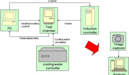
The thermal fatigue test system described in Figure 1 consists of 5 main modules, controller(PC), test chamber, induction heater, cooling water controller and image capturer. A specimen is heated by an induced current from the induction heater. The temperature of the specimen increases to a maximum value, then the specimen in the gripper drops into cooling water. The cooling water’s temperature is kept up at 25 ±2℃ by cooling water controller. This process is repeated for 10 cycles and then the specimen is taken out for the examination of crack initiation and growth by optical microscopy . Cracks on the specimen surface are regularly checked during the test and the test is finished at 400 cycles. The conditions of this test are given in Table 1.
Figure 1 – Thermal fatigue test system
Table 1 - Test conditions
Conditions Value Test temperature Tmax = 600℃
Tmin = 40℃
Tcoolwater = 25 ±2℃
Interval of Observation 0 ~ 250 : every 10 cycles 250~400 : every 30 cycles
Test specimens
The test was performed on a specimen made from brake disk used for the Saemaul and Mugunghwa trains. It has a cylindrical shape to be heated uniformly by induction coil. The dimension and chemical compositions of the specimen are given in Figure 2 and Table 2 respectively.
Analysis
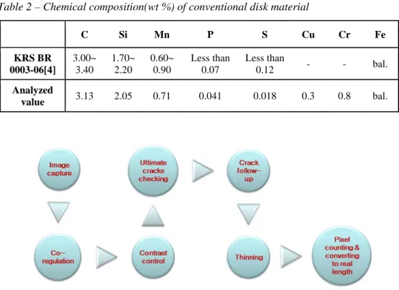
The thermal crack analysis procedure and a program were developed for evaluation of material’s heat resistance. Figure 3 shows the process to analyse the crack length. The analysis program was coded by the C++ and the OpenCV was used as an image process library. We can perform the pre-processing for analysis and estimation of thermal crack length on selected surface area by the developed crack analysis program.
Figure 2 – Dimension of the specimen
Table 2 – Chemical composition(wt %) of conventional disk material
C Si Mn P S Cu Cr Fe KRS BR
0003-06[4]
3.00~
3.40
1.70~
2.20
0.60~
0.90
Less than 0.07
Less than
0.12 - - bal.
Analyzed
value 3.13 2.05 0.71 0.041 0.018 0.3 0.8 bal.
RESULTS
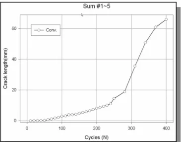
At the end of the test, 30 images were captured from an area and 150 images from 5 areas of the specimen were totally gained. Some observed sample images are shown in Figure 4. Each area #1 ~ #5 is 4.48×3.59 mm2. The real length of thermal crack was calculated from each area and total crack lengths of 5 areas were summed up. In Figure 5, A graph shows accumulated crack length of the specimen as a result of this test.
Figure 5 – Accumulated crack length to 400 cycles (a) 50 cycles
(b) 10 cycles (c) 100 cycles
(d) 200 cycles (e) 310 cycles (f) 400 cycles
Figure 4 – Crack images
CONCLUSIONS
In this study, a procedure to evaluate the heat resistance of brake disk materials was developed. And then we analysed the thermal crack images from a test specimen by the developed analysis program. The following conclusions were deduced from the results of this study.
- We could suggest the test system, the feature of specimen and proper test temperature for this thermal fatigue test.
- The usability of developed crack analysis program and image process was verified by this study.
- It is desirable to develop a full automatic crack analysis procedure to obtain more objective results.
REFERENCES
[1] V. Maillot, A. Fissolo, et al., “Thermal fatigue crack networks parameters and stability: an experimental study”, Int.
J. Solids and Structures, Vol. 42, 759-769 (2005)
[2] Sebatien Amiable, et al., “A comparison of lifetime prediction methods for a thermal fatigue experiment”, Int. J.
Fatigue, Vol. 28, 692-706 (2006)
[3] Andrezej weronski, Tadeusz hejwowski, Thermal Fatigue of Metals.(Marcel Dekker, Inc., New York, 1991) [4] Brake Disk, KRS BR 0003-06 (2006)