Progress in Superconductivity and Cryogenics
Vol.16, No.4, (2014), pp.57~61 http://dx.doi.org/10.9714/psac.2014.16.4.057
```
1. INTRODUCTION
In a wind power farm, the output fluctuation occurs under the influence of weather. In addition, in case of the proportion of wind power is larger than critical percentage of the total power generation sources, it disturbs the stability of the power system and debases the quality of the electric power. According to the 15th article of Electric utility law, grid connection standards for renewable generator, the active power output fluctuation rate per minute is limited to 10% of rated electric capacity.
At the present time, output fluctuation is controlled by limiting output artificially like droop control, and it can be a huge economic loss from the point of business operator’
view because of reduction of plant factor. Currently, there are many researches related to the compensation of the output fluctuation in wind power farm have been dealt in terms of the fluctuation rate in wind power farm output is reduced. It means that energy will be emitted in the section of rising rate and absorb in the section of falling rate, as well. At that time, an electric energy storage (EES) is used, and it will charge and discharge quickly without power loss of large electric capacity.
A superconducting magnetic energy storage (SMES) can quickly charge and discharge high energy density with high efficiency since the SMES charges and discharges energy by the current source. A SMES has a very profitable performance for the compensation of output fluctuation by surpassing charging and discharging characteristics. Nevertheless, the current variation within superconducting magnet that is induced during charging
and discharging period will generate electromagnetic losses. These losses consist of magnetization loss within superconducting wire and eddy current loss in the surrounding metallic components. The heat generated by these two losses can disturb the operation stability of a SMES that has a thermally sensitive [1].
Therefore, in this paper, the wind power output will be effectively improved by applying SMES application instead of conventional EESs. In addition, the electromagnetic losses in SMES were calculated according to current variation where has been analyzed by numerical analysis. Finally, thermal characteristic of SMES was analyzed using 3D finite-element analysis (FEA).
2. CHARACTERISTIC OF THE SMES DURING FLUCTUATION COMPENSATION 2.1. Conceptual Design of the 1 MJ Class SMES
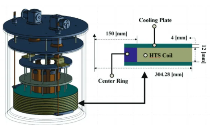
Fig. 1. Basic conceptual design of the 1 MJ SMES system.
Analysis of losses within SMES system for compensating output fluctuation of wind power farm
S. I. Parka, J. H. Kimb, T. D. Leb, D. H. Leea, D. J. Kimb, Y. S. Yoonc, K, Y, Yoond, and H. M. Kim*, b
a Faculty of Wind energy Engineering, Jeju National University, Jeju, S. Korea
b Department of Electrical Engineering, Jeju National University, Jeju, S. Korea
c Department of Electrical Engineering, Shin Ansan University, Ansan, S. Korea
d Department of Electrical and Electronic Engineering, Yonsei University, Seoul, S. Korea (Received 14 November 2014; revised or reviewed 22 December 2014; accepted 23 December 2014)
Abstract
Output fluctuation which is generated in wind power farm can hinder stability of total power system. The electric energy storage (EES) reduces unstable output, and superconducting magnetic energy storage (SMES) of various EESs has the proper performance for output compensation of wind power farm since it charges and discharges large scale power quickly with high efficiency.
However, because of the change of current within SMES, the electromagnetic losses occur in the process of output compensation.
In this paper, the thermal effect of the losses that occur in SMES system while compensating in wind power farm is analyzed. The output analysis of wind power farm is processed by numerical analysis , and the losses of SMES system is analyzed by 3D finite element analysis (FEA) simulation tool.
Keywords: eddy current loss, magnetization loss, superconducting magnetic energy storage, wind power farm
* Corresponding author: [email protected]
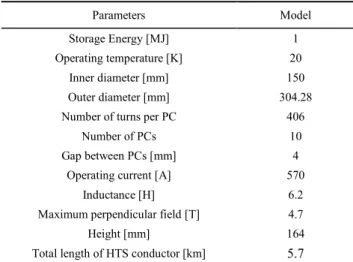
TABLE I
SPECIFICATIONS OF THE 1MJ CLASS SMES.
Parameters Model
Storage Energy [MJ] 1
Operating temperature [K] 20
Inner diameter [mm] 150
Outer diameter [mm] 304.28
Number of turns per PC 406
Number of PCs 10
Gap between PCs [mm] 4
Operating current [A] 570
Inductance [H] 6.2
Maximum perpendicular field [T] 4.7
Height [mm] 164
Total length of HTS conductor [km] 5.7 Fig. 1 and Table I show the basic conceptual design and specification parameters of the 1-MJ-class SMES, respectively. The YBCO coated conductor with 12 mm width and 0.38 mm thickness is used for superconducting coil.
The SMES magnet is a multiple pancake coil shape which is designed by optimizing the superconducting wire length. It consists of 10 single pancake coils which has 4 mm air gap between each coil. The total length of the superconducting wire length is 5.7 km. In consideration of the in-field property of 30 K, maximum operating current and temperature is 570 A, and 20 K, respectively.
Moreover, it has been confirmed that the critical current was not reduced due to the magnetic flux density of the perpendicular direction through 3D FEM Electromagnetic analysis. The superconducting magnet of 1-MJ-class SMES is cooled by the conduction cooling method using two GM cryocoolers. Bobbins of SMES magnet are made of aluminum alloy and serves as the thermal conduction plates for the conduction cooling. They consist of cooling plates and center rings. Then, they connect conduction bar to the 2nd stage of cryocooler [2, 3].
2.2. Numerical Analysis of Compensation Output Fluctuation of Wind Power Farm
In this section, the suitable electric capacity of SMES was calculated, which needed in the course of controlling wind power farm in terms of renewable energy regulation.
Furthermore, the expected effect of output compensation was analyzed when 1-MJ-class SMES is connected to power grid. Actual output data of the Hang-won wind power farm in Jeju island was used for the analysis, and it is based on a data during the day in winter season. The Hang-won wind power farm has 9.795 MW facility and 12 wind power generators which are miscellaneous in manufacturer and operation duration. According to the regulation, the output fluctuation, which either exceeds or not about 0.979 MW, i.e., 10% of electric capacity in wind farm per one minute should be mitigated and compensated, respectively. Therefore, the accumulated fluctuation rate per one minute has been maintained in a range margin between ±10% based on electric capacity in wind farm.
Fig. 2. Schematic diagram of SMES system.
Fig. 3. Required current at each second (a) and current capacity (b) for compensating output fluctuation of wind power farm.
Fig. 4. The compensation effect of output fluctuation (a) and current variation in SMES (b).
S. I. Park, J. H. Kim, T. D. Le, D. H. Lee, D. J. Kim, Y. S. Yoon, K, Y, Yoon, and H. M. Kim
It will be done by counting the total amount of real wind power farm output data. However, if the output fluctuation eclipses the range of ±10%, SMES is connected to power system by charging and discharging the current needed to mitigate and compensate. The schematic diagram of SMES system is shown in Fig. 2.
Fig. 3 (a) and (b) illustrate that the current variation in seconds and current capacity required for improving output fluctuation of wind power farm, respectively. The necessary current capacity for SMES was calculated by integrating amount of current because the current value was calculated as each second unit. The current capacity of the SMES was computed as 150 kA in consideration of usable electric capacity since the charging and discharging amount of stored current in SMES is limited. As a result of the PSCAD simulation, there is a significant improvement effect of fluctuation output as shown in Fig. 4 (a) and the current variation in SMES is followed in Fig. 4 (b) [2].
2.3. AC Losses of SMES
AC loss in superconducting coils of SMES can generate because the charging and discharging current capacity is changed according to required power in wind farm. The magnetization loss will generate within superconducting wire due to penetration effect if AC current flows in coils.
Moreover, eddy current loss can generate in surrounding metallic components by alternating magnet field. These AC losses generate heat loss and reduce the performance of sensitive SMES thermally, so the analysis for AC losses is very important. In order to consider weak operating conditions thermally, the loss analysis was performed with 60 second section which can generate the largest loss, and the maximum heat loss is also used for thermal analysis.
2.3.1. Magnetization Loss
The magnetic flux density of perpendicular direction is much larger than parallel direction because of phenomena of anisotropic characteristic of superconducting wire.
Magnetization loss was calculated based on Brandt strip model as Eq. 1 and 2 below and as finding magnetic flux density value of perpendicular direction by 3D FEM simulation [4, 5].
𝑃⊥= (2𝜋𝑤(𝐵𝑎)2)/(2𝛽𝑑𝜇0)
[(2ln (cos ℎ(𝛽))/𝛽 − tan ℎ(𝛽) )] 𝑉𝑓 (1) 𝐵𝑝⊥= (𝜇0 𝐽𝑐 𝑑𝑐)/𝜋 (2) Where w and d represent the width and the thickness of a wire of composite conductor, respectively. 𝜇0 represents the permeability of vacuum, 𝛽 is defined as Ba/Bp. While Ba is the amplitude of magnetic field, and Bp is the penetration field at zero transport current. Jc and dc
represent the critical current density and the thickness of the core of the superconducting wire, respectively.
Magnetization loss is proportional to the magnitude of magnetic flux density which is proportional to the magnitude of the current. Therefore, magnetization loss reaches the highest average value shown in Fig. 5.
Fig. 5. Analysis section of magnetization loss.
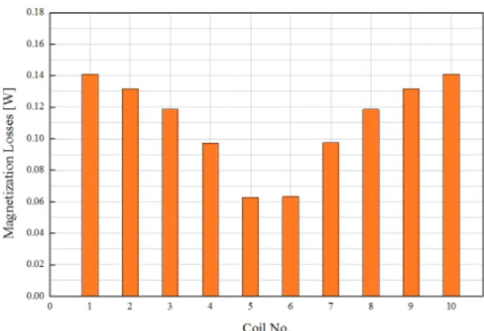
Fig. 6. Maximum magnetization loss of each coil.
Magnetization loss value of each coil was calculated by using the maximum magnetic flux density of perpendicular direction of each coil because magnetic flux density of perpendicular direction is similar in each coil. Fig. 6 shows the magnetization loss values which occur in each coil at 81157.8 second. The maximum magnetization loss is 1.4 W at both of the top and the bottom coil and the minimum loss value is around 0.63 W at the middle coil in the average frequency of 1/60 Hz.
2.3.2. Eddy Current Loss
Eddy current loss which occurs due to alternating magnetic field was analyzed for the adjacent metallic component to coil where it can be generated largely.
Analysis section of eddy current loss and variation of eddy current loss of total adjacent component by current variation per second is shown in Fig. 7. Eddy current analysis section is maximum variation of SMES current for 60 second because eddy current is proportional to variation of the magnetic flux density.
Maximum total eddy current loss is 858.8 mW at 23423.7 second as shown in Fig. 7. Eddy current density distribution of center rings, cooling plates and conduction bars at 23423.7 second is shown in Fig. 8. The highest eddy current flows were confirmed in the cooling plate at middle point.
59
Fig. 7. Analysis section of eddy current loss and total eddy current loss of adjacent parts of coil.
(a)
(b)
(c)
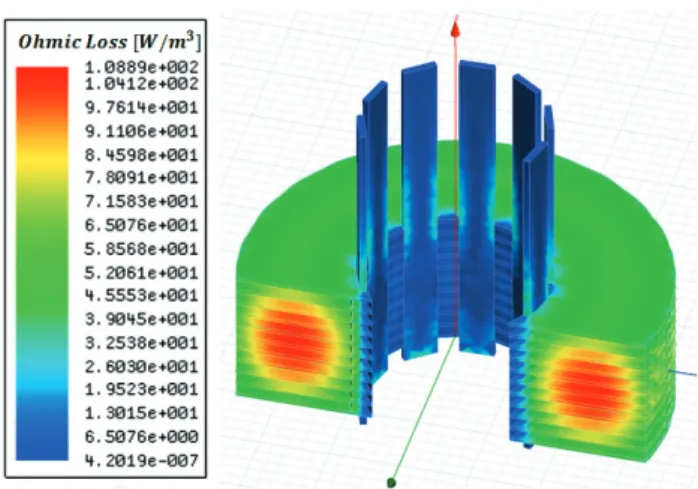
Fig. 8. Eddy current density distribution of center rings (a), cooling plates(b) and conduction bar (c).
Fig. 9. Resistance loss distribution of adjacent parts of coil.
Resistance loss distribution by eddy current at 23423.7 second is shown in Fig. 9. It was confirmed that the resistance loss is generated according to the eddy current distribution. It is easily seen that the high value generating on the contact is proportional to the conduction bar in the center ring, adjacent cooling plate of middle point of the magnet, contact surface with coil of conduction bar.
2.4. Thermal Analysis
In order to analyze the thermal characteristics, the other heat losses except for magnetization and eddy current losses were analyzed as shown in Table II.
TABLE II
LOSSES OF SMES SYSTEM.
Loss Value [W]
Magnetization loss 1.103
Eddy current loss 0.858
Radiation heat loss 0.89
Conduction loss G10 - Rods 0.001
Joint heating loss 0.93
Current lead 0.12
Fig. 10. Temperature distribution of the SMES system.
S. I. Park, J. H. Kim, T. D. Le, D. H. Lee, D. J. Kim, Y. S. Yoon, K, Y, Yoon, and H. M. Kim
Temperature distribution of 1-MJ-class SMES is shown in Fig. 10, and it indicates that about 4.2 K rise on basis of operating temperature 20 K. Moreover, it could be also confirmed that designed SMES is a stable system for improving output power fluctuation because we have considered temperature margin of 10 K in step of initial design [6].
3. CONCLUSION
In this paper, effect of compensating output in wind power farm by applying a SMES system, losses from current variation within SMES and SMES’s thermal stability have been analyzed. The estimation of grid using SMES was analyzed by using numerical analysis.
Moreover, its improvement and current variation are calculated accordingly.
As results of applying the SMES to power system, it confirms that the output fluctuation of real grid is effectively mitigated and compensated.
An analysis of AC losses including magnetization and eddy current losses has been performed by 3D FEM simulation. The maximum magnetization and eddy current losses were calculated to 1.5 W, 0.85 W, respectively. The thermal analysis was carried out by considering to AC losses and the other heat losses. Moreover, it is reliable to stably operate SMES from all losses due to current changes which occur in the course of output improvement.
ACKNOWLEDGMENT
This work was supported by Graduate School of Specialized Wind Energy the Human Resources Development and International Collaborative R&D Program of Energy Technology Evaluation and Planning (KETEP) grant funded by the Korea government Ministry of Trade, Industry and Energy (20094020200020), (20118520020020).
EXAMPLE REFERENCES
[1] Abbas A. Akhil, DOE/EPRI 2013 electricity storage handbook in collaboration with NRECA, sandia national laboratories, 2013.
[2] S. Park, “A Study on the Design and Characteristic Analysis of the 1 MJ Class SMES for Variable Electric Power Compensation of Wind Farm,” Master of science thesis, Faculty of wind energy engineering, jeju national university, Feb. 2015.
[3] S. Lee, “Analysis of eddy current losses and magnetization losses in toroidal magnets for a 2.5 MJ HTS SMES,” IEEE Trans. Applied superconductivity, vol. 21, no. 3, pp. 1354-1357, 2011.
[4] M. J. Lee, “AC Loss and thermal stability of HTS model coils for a 600 kJ SMES,” IEEE Trans. Applied superconductivity, vol. 17, no.
2, pp. 2418-2421, 2007.
[5] Y. Xu, “Distribution of AC loss in a HTS magnet for SMES with different operating conditions,” Physica C Superconductivity, vol 494, no. 15, pp. 213-216, 2013.
[6] T. Le, “Thermal design of cryogenics cooling system for 10 MW class high temperature superconducting rotating machine,” Applied superconductivity conference 2014, June 2014.
61