학 술 논 문
105
손동작 영상획득을 이용한 최소침습수술로봇 무구속 마스터 인터페이스
장익규
구미전자정보기술원 전자의료기술연구본부
Non-restraint Master Interface of Minimally Invasive Surgical Robot Using Hand Motion Capture
Ik-Gyu Jang
Gumi Electronics & Information Technology Research Institute, Electronic medical Technology Research Division, R304 Biomedical IT Convergence Center Main building, 350-27 Gumidaero, Gumi, Gyeongbuk, Korea
(Manuscript received 11 May 2016; revised 22 June 2016; accepted 23 June 2016)
Abstract: Introduction: Surgical robot is the alternative instrument that substitutes the difficult and precise surgical operation; should have intuitiveness operationally to transfer natural motions. There are limitations of hand motion derived from contacting mechanical handle in the surgical robot master interface such as mechanical singularity, isot- ropy, coupling problems. In this paper, we will confirm and verify the feasibility of intuitive Non-restraint master inter- face which tracking the hand motion using infra-red camera and only 3 reflective markers without the hardware handle for the surgical robot master interface. Materials & methods: We configured S/W and H/W system; arranged 6 infra-red cameras and attached 3 reflective markers on hands for measuring 3 dimensional coordinate then we find the 7 motions of grasp, yaw, pitch, roll, px, py, pz. And we connected Virtual-Master to the slave surgical robot(Lap- arobot) and observed the feasibility. To verify the result of motion, we compare the result of Non-restraint master and that of clinometer (and protractor) through measuring 0~180 degree, 10degree interval, 1000 samples and recorded standard deviation stands for error rate of the value. Results: We confirmed that the average angle values of Non-restraint master interface is accurately corresponds to the result of clinometer (and protractor) and have low error rates during motion. Investigation & Conclusion: In this paper, we confirmed the feasibility and accuracy of 3D Non-restraint master interface that can offer the intuitive motion of non-contact hardware handle. As a result, we can expect the high intuitiveness, dexterousness of surgical robot.
Key words: Surgical robot, High-Intuitiveness, Master interface, Non-restraint, Coupling
I. 서 론
상용 수술 로봇은 크게 수술을 수행하는 수술도구(Slave) 부분과 수술자가 손동작을 입력하는 조종간(Master) 부분 으로 나뉜다. 이러한 구조는 조종간(Master)에서 입력하는 손동작의 자유도와 수술도구(Slave) 동작의 자유도사이의
인터페이스를 연결하는 과정에서 상대적으로 크기가 큰 움 직임을 작고 정밀한 수술도구 동작으로 변환해 주고 복잡한 복강경 수술 동작을 기구학적으로 직관적 움직임이 가능하 게 하여 사용시 최소 침습적 수술을 가능하게 하였다[1]. 이 방법은 Da vinci[2]와 같은 기존의 수술로봇에 적용되어 직 관적 수술 수행에 크게 기여 하였지만 복잡한 기계식 핸들 로 구성된 조정간(Master)이 손에 접촉되어 있어 조작시 사 람과 기계간 및 링크간 물리적 간섭[2], 기계적 특이점[3-6], 등방성[7-10] 등의 문제가 발생하여 직관적인 수술동작 수 행에 제약이 있었고 마스터 인터페이스에서 자연스러운 움 Corresponding Author : Ik-Gyu Jang
(39253) Biomedical IT Convergence Center Main building, R304, 350-27 Gumidaero, Gumi, Gyeongbuk
TEL: +82-54-467-8021 / E-mail: [email protected]
106
직임을 구현하기 위한 마스터에 대한 연구들이 여러 분야에 서 이루어 졌다[6,11-14].
이런 다양한 마스터 방법 중에서 모션 측정방법이 있는데, 영상을 이용한 방법, 초흠파를 이용한 방법, 자기식 모션센 서를 이용한 방법등이 있었다. 영상을 이용한 동작 분석방 법[13]은 다양한 환경에 대해서 포인트의 위치가 가변적이 고 연산량이 많으므로 엄격하게 실시간으로 정확한 결과를 얻기 힘들었다. 또한 초음파를 이용한 동작분석[14]은 비교 적 크기가 큰 디바이스를 손에 장착하여야 하므로 사용하는 데 어려움이 있었다. 자기식 모션센서는 공간적 해상도가 낮 아[6] 손에 여러 개의 마커를 근접하여 부착하기 어렵고, 자 이로 센서[12]는 3D 모션의 각도를 알 수 있지만 정확한 병 진 동작을 알기 위해서 추가적으로 센서가 필요하며 상대적 으로 큰 오차를 보였다[15]. 자연스러운 움직임을 구현하기 위해서 적외선 카메라를 이용하여 모션을 분석하는 많은 연 구들이 있었지만[11,16-19] 수술로봇에 적합하게 조작할 수 있도록 마스터 인터페이스를 구현한 사례는 없었다.
이 논문에서는 마스터에서 수술동작에 필요한 손동작을 적 외선 카메라로 위치를 검출, 공간상 동작정보를 계산, 실시간 전달하여 슬레이브 수술도구를 제어하는 무구속 마스터 인터 페이스가 가능함을 확인, 검증 한다. 이를 통해 수술 수행 시 동작이 좀 더 직관적(intuitive)인 움직임을 구현할 수 있다.
II. 재료 및 방법
1. H/W 시스템 구성
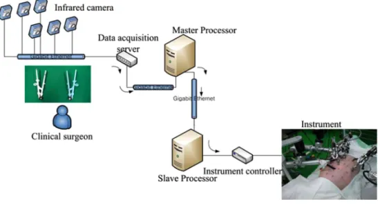
무구속 마스터 인터페이스를 구성하기 위해 적외선 카메 라 6대를 그림 1과 같이 대상이 잘 검출될 수 있도록 배치하 고 마커(10 mm Model; Vicon Motion Systems, Oxford,
UK)는 정해진 마스터 인터페이스 포셉에 3개를 부착한다.
6 대의 카메라(MX3+
TMModel; Vicon Motion Systems, Oxford, UK) 를 사용하여 측정된 적외선 영상 데이터는 그림 2 와 같이 적외선 영상 데이터 획득 서버(MXULTRANET
TM; Vicon Motion Systems, Oxford, UK) 에 연결되어 전달된 다. 서버와 연결된 마스터 프로세서(xw4400 workstation;
Hewlett-Packard, CA, US) (Windows RTX; Interval- Zero; US) 에서 카메라 제어 소프트웨어(Vicon Nexus
TM; Vicon Motion Systems, Oxford, UK) 프로그램과 cali- bration wand (14 mm L-frame 5 marker wand; Vicon Motion Systems, Oxford, UK) 를 사용하여 3차원 좌표 계를 설정한다. 손동작이 촬영되기 시작하면 영상데이터가 적외선 카메라, 데이터 수집서버, 마스터 프로세서, 슬레이브 프로세서를 따라 수술도구 컨트롤러를 통해서 수술도구를 제 어하게 된다. 슬레이브 프로세서(Linux Ubuntu 11.04;
Canonical Ltd.; UK) 는 마스터 프로세서와 UDP연결을
그림 1. 무구속 마스터와 슬레이브 수술도구.Fig. 1. Virtual Master (up) & Slave surgery instrument (down).
그림 2. H/W 시스템 연결 구성.
Fig. 2. H/W System connection configuration.
107 통해 데이터 페킷을 받으며 한 개의 팔을 동작하기 위해 다
섯 개의 모터 컨트롤러(EPOS 24/5; Maxon; Swiss)와 CAN (Control Area Network) (CAN 4xHS; Kvaiser; Sweeden) 로 연결되어 있으며 다섯 개의 모터(M050138; Maxon motor; Swiss), (283840; Maxon motor; Swiss), (309652;
Maxon motor; Swiss), (304909; Maxon motor; Swiss), (343120; Maxon motor; Swiss) 가 각각 모터 컨트롤러에 연결되어 있다.
2. S/W 시스템 구성
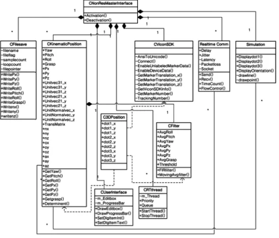
S/W 는 그림 3과 같이 객체지향적 모델 설계 도구 (Unified Modeling Language-UML; Object Modeling technique- OMG, USA) 를 이용하여 설계하였으며 최상위에 한 개의 클래스를 두어 사용자가 activation과 deactivation만 동작 할 수 있도록 사용자 인터페이스를 단순화 하였다. 내부적 으로 최대 240 frame/sec의 실시간 영상을 처리를 지원하 고, 추후 슬레이브로의 송신 작업 우선순위를 부여하여 송 신 작업 스케줄링을 위해서 실시간 운영체제(windows xp RTX MP dedicated; IntervalZero, MA, US) 를 사용하며 Virtual Master 클래스에서는 이러한 기능을 지원하고 반 복적으로 실시간 동작 데이터를 처리하도록 하기 위해서 쓰
레드(Thread)를 사용한다. 이러한 방식은 마스터와 슬레이 브간 실시간 통신을 수행할 때 지연을 최소화 시켜준다.
3. 사용 알고리즘
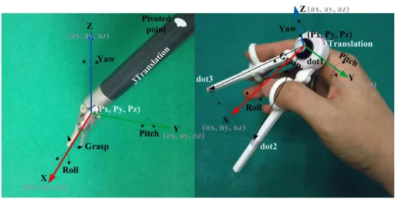
그림 4에서 보는 바와 같이 포셉과 결속한 손의 엄지와 검지 사이를 잇는 점을 dot1, 엄지쪽을 dot2, 검지쪽을 dot3 로 정한다. dot1, dot2, dot3를 이용하여 하나의 이동 좌표 계를 구하고 기구학을 이용하여[20] 슬레이브 수술도구의 3 동작 roll, pitch, yaw을 구하게 된다. 좌표계를 구하는 절 차는 먼저 dot2와 dot3의 이등분점과 dot1을 잇는 단위벡 터를 평면의 움직이는 좌표계의 x축, dot1-dot2 벡터와 dot1-dot3 벡터를 cross product하여 구한 단위 법선 벡터 를 평면의 움직이는 좌표계의 z축 그리고 x, z축에 동시에 수직인 벡터를 y축으로 놓는다. 이 움직이는 좌표계의 단위 벡터 n축(x축)이 전역좌표계와 이루는 x, y, z 벡터성분을 각각 n
x, n
y, n
z라 하고 움직이는 좌표계의 a축(z축)이 전 역좌표계와 이루는 x, y, z 벡터성분을 각각 a
x, a
y, a
z라 하 며 움직이는 좌표계의 o(y축)이 전역좌표계와 이루는 x, y, z 벡터성분을 각각 o
x, o
y, o
z라 한다. 또한 움직이는 좌표 계의 병진운동(Translation)이 dot1의 px, py, pz이라 할 때 12개의 변수를 가진 한 개의 변환행렬이 만들어진다. 여
그림 3. 무구속 마스터 인터페이스의 소프트웨어 구조.
Fig. 3. S/W System Configuration of Virtual Master interface.
108
기서 a축에 관한 회전을 roll 이라고 하며, o축에 관한 회 전을 pitch라고 하며, n축에 관한 회전을 yaw라고 할 때 RPY 방위 변화를 구하는 식은 다음과 같다[20].
Roll : φ
a= φ
a= ATAN2(n
y, n
x) or ATAN2( −n
y, −n
x) (1) Pitch : φ
o= φ
o= ATAN2( −n
z, (n
xCos φ
a+ n
ySin φ
a))
(2)
Yaw : φ
n= ATAN2[( −a
yCos φ
a+ a
xSin φ
a), (o
yCos φ
a− o
xSin φ
a)]
(3)
Where ATAN2(y,x) =
점 3개의 좌표는 손 동작을 취했을 때에도 점의 라벨은 바뀌지 않게 포인트 트레킹을 사용하여 점의 움직임을 추적 한다. 포인트 트레킹(Point tracking)은 Kull-back-Leibler divergence 나 Bhattacharyya coefficient와 같은 대표적 인 방법이 있으나 두 방법 모두 로그(logarithm) 함수를 사 용하여 입력되는 인자사용에 제한이 발생하므로 여기서는
RMSE(Root Mean Square Error) 를 사용하여 동작 이 전 점 세 개와 동작 이후 점 세 개간 포인트의 RMSE 가 가장 적은 위치의 포인트를 자신의 포인트로 인식한다.
4. 검증 및 분석
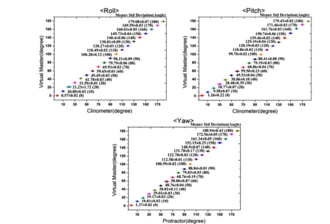
이 논문에서는 무구속 마스터 인터페이스의 성능을 검증 하기 위해서 roll, pitch, yaw 동작을 취할 수 있는 삼각대 (Manfrotto; 161MK2; Italy) 를 이용하여 roll동작만 취했 을 때, pitch 동작만 취했을 때, yaw동작만 취했을 때 세 개 의 동작의 자유도를 동시 측정하여 살펴보았다. Roll, pitch, yaw 동작은 나머지 px, py, pz 좌표와 Grasp을 구하기 위 한 두 개의 벡터를 모두 포함하고 있는 값이므로 이 RPY 동작을 검증하면 된다.
정확성을 검증하기 위해서 Roll, pitch는 수평계(Clino- meter; DL-155V, Japan) 를 이용한 측정 각도와 무구속 마 스터 계산 결과 평균값을 비교하고, Yaw은 삼각대의 각도 기(Manfrotto; 161MK2; Italy)를 이용하여 측정한 결과와 무구속 마스터 결과 평균값을 비교하여 사용 가능성을 살펴 본 후 표준편차를 구하고 신뢰구간, 오차를 분석하였다. 결 과는 각도당 1000개 샘플을 사용하였다.
III. 결 과
자연스러운 동작이 가능한지 여부를 확인하기 위해서 수 술동작시 대표적인 동작인 직선동작, 원동작, 8자 동자를 국 립암센터 전문의가 취하고 각10회를 기록하여 분석하였다.
기계식 마스터와 무구속 마스터를 비교한 세 가지 모션의 병진동작의 궤적을 3차원 좌표로 표현하였다. 기계식 마스 터는 Phantom Premium(Sensable Raleigh, NC, USA) arc y
x --
⎝ ⎠ ⎛ ⎞
tan x 0 >
arc y x --
⎝ ⎠ ⎛ ⎞ π +
tan y 0 ≥ x 0 , <
arc y x --
⎝ ⎠ ⎛ ⎞ π –
tan y 0 < x 0 , <
+π --- y 0 2 > x , = 0
-π 2 --- y 0 < x , = 0 Undefined y 0 x 0 = , =
⎩ ⎪
⎪ ⎪
⎪ ⎪
⎪ ⎪
⎪ ⎨
⎪ ⎪
⎪ ⎪
⎪ ⎪
⎪ ⎪
⎧
그림 4. 슬레이브 수술도구와 손동작의 대응.
Fig. 4. Slave surgical instrument and corresponding of hand motion.
109
를 사용하였고 집게동작을 제외한 6자유도 모션을 취할 수 있다. 무구속 마스터와 기계식 마스터를 스레이브 로봇이 피 봇(Pivot)된 상태에서 동작하였고 궤적을 mm단위로 기록 하였다.
측정후 정확성을 살펴보기 위해 x축-수평계 및 각도기 측 정 값과 y축-무구속 마스터 결과와의 비교값을 표현하였고, 각도당 1000회 sampling 된 값의 평균과 표준편차를 표기 하였다. 각 동작은 10도 간격으로 0도에서180도까지 측정
하였다.
무구속 마스터와 기울기 센서의 값을 비교해 본 결과 그 림 6와 같이 0~180 도까지 표준편차 0.003~0.47도를 보이 므로 정밀하다는 사실을 확인할 수 있다.
IV. 조사 및 결론
그림 5에서 보이는 바와 같이 직선동작 및 원동작, 8자동
그림 5. 무구속 마스터와 기계식 마스터의 궤적.Fig. 5. Translation trajectories of the mechanical-left and non-restraint-right (mm): (a) straight-line motion, (b) circular motion, and (c) eight-shape motions.
110
작에서 기계식 마스터 보다 무구속 마스터의 움직임이 좀더 우수함을 알 수 있다. 이러한 차이는 정밀한 수술동작에서 더욱 차이가 날 것으로 기대한다. 그림 6에서 보이는 바와 같이 오차는 신뢰구간에서 발생하는 측정장비가 가지는 공간 해상도 오차로서 Roll은 ± 0.002~0.47도, Pitch는 ± 0.002~
0.078 도 그리고 Yaw는 ± 0.003~0.087도를 보이고 있다.
이 논문에서 우리는 손동작을 제한하는 하드웨어 핸들을 사 용하지 않고 높은 시공간 해상도(spatio-temporal resolu- tion) 의 적외선 카메라로 포셉과 결속한 손 동작을 분석하 여 결과를 확인함으로써 자연스러운 움직임을 구현할 수 있 었고 측정결과를 통해 사용가능성과 정확성이 확인되었다.
하지만 주변의 원하지 않는 적외선이 검출될 수 있고 가능 한 동작영역을 정하여 벗어나지 않도록 마스터 콘솔을 구성 하는 것이 필요하고 콘솔 제작 시 손동작영역에서 불필요한 빛이 차단되도록 마스터 콘솔을 설계하는 것이 필요하다.
References
[1] Mitsuishi M., “Medical Robot and Master Slave System for Minimally Invasive Surgery,” in Complex Medical Engineer- ing, 2007. IEEE/ICME International Conference on, 2007, pp. 8-13.
[2] Y. Komoguchi, et al., “Redundancy resolution of a 7DOF
haptic interface considering colloision and singularity avoid- ance,” in International Conference on Intelligent Robots and Systems Acropolis Convention Center, Nice, France, 2008, pp. 3513-3518.
[3] GAV Christiansson and E. Fritz, “A novel planar 3-DOF hard-soft haptic teleoperator,” in Sencond Joint EuroHaptics Conference and Symposium on Haptic Interface for Virtual Environment and Teleoperator Systems, 2007, pp. 361-366.
[4] HW Kim, et al., “Singularity-free load distribution algorithms for a 6DOF parallel haptic device,” in Proceedings of the 2004 IEEE International Conference on Robotics & Automa- tion, New Orleans, 2004, pp. 298-304.
[5] K Nagase and S. Katsura, “Bilateral control considering sin- gularity based on observation of torque error,” in The 11th IEEE International Workshop on Advanced Motion Control, Nagaoka, 2010, pp. 744-749.
[6] T. Molet, et al., “A Real Time Anatomical Converter For Human Motion Capture,” in In Eurographics Workshop on Computer Animation and Simulation 1996, pp.79-94.
[7] JH Chung, et al., “Implementation of foldable 3DOF master device to handle a large glass plate,” in International Confer- ence on Intelligent Robot and Systems Louis, 2009, pp. 741- 747.
[8] LJ Socco, et al., “On the use of scaling matrices for task spe- cific robot design,” IEEE transactions on Robotics and Auto- mation, vol. 15, pp. 958-965, 1999.
[9] MJH Lum, et al., “Optimization of a spherical mechanism for a minimally invasive surgical robot: Theoretical and experimental approaches,” IEEE transactions on Biomedical Engineering, vol. 53, pp. 1440-1445, 2006.
그림 6. 무구속 마스터와 수평계 및 각도기와 비교한 값.
Fig. 6. Comparison between virtual master and clinometer (protractor).
111
[10] T Huang, et al., “Optimal kinematic design of 2 DOF parallelmanipulators with well shaped workspace bounded by a specified conditioning index,” IEEE transactions on Robot- ics and Automation, vol. 20, pp. 538-543, 2004.
[11] A.G. Kirk, et al., “Skeletal Parameter Estimation from Opti- cal Motion Capture Data,” in CVPR 2005, 2004, pp. 782- 788.
[12] J. Borenstein and L. Feng, “Gyrodometry: A New Method for Combining Data from Gyros and Odometry in Mobile Robots,” in Proceedings of the 1996 IEEE International Conference on Robotics and Automation, Minneapolis, 1996, pp. 423-428.
[13] J. Deutscher, et al., “Articulated body motion capture by annealed particle filtering,” in Computer Vision and Pattern Recognition, 2000. Proceedings. IEEE Conference on, SC, USA, 2000, pp. 126-133.
[14] Y. Nishida and K. Kitamura, “Quick Realization of Function for Detecting Human Activity Events by Ultrasonic 3D Tag and Stereo Vision,” in IEEE International Conference on Pervasive Computing and Communications, 2004, pp. 43-54.
[15] T.L. Grigorie and D.G. Sandu, “The influences of the gyro
sensors' errors on the attitude calculus,” in 49th International Symposium ELMAR 2007, Zadar, 2007, p. 85.
[16] F. Wang, et al., “Gait analysis and validation using voxel data,” in 31st Annual International Conference of the IEEE EMBS, Minneapolis, Minnesota, 2009, p. 6127.
[17] H.M. Je, et al., “Hand gesture recognition to understand musical conducting action,” in IEEE International Confer- ence on Robot & Human Interactive Communication, Jeju, Korea, 2007, p. 163.
[18] J.E. McNamara, et al., “Motion capture of chest and abdom- inal markers using a flexible multi-camera motion-tracking system for correcting motion-induced artifacts in cardiac SPECT,” in Nuclear science symposium conference record, 2007., Honolulu, HI, 2007, p. 4289.
[19] W. Tian, et al., “Spatio-temporal characteristics of human gaits based on joint angle analysis,” in 3rd IEEE Interna- tional Conference on, Chengdu, 2010, p. 439.
[20] S.B. Niku, “Robot kinematics: position analysis,” in Intro- duction to robotics analysis, systems, applications, ed CA:
Prentice hall, 2002, pp. 68-72.