2015년도 학회상 수상 자료
Yunho Hwang Department of Mechanical Engineering,
University of Maryland, College Park, MD, USA ([email protected]) Rin Yun
Department of Mechanical Engineering, Hanbat National University, Daejeon, Korea ([email protected])
Inflow Condensation Heat Transfer Characteristics of
CO 2 in Microchannel
Introduction
Carbon dioxide refrigeration system has been utilized for water heaters, mobile air condition
ing systems, bending machines, and room air conditioners. Now, the system expands its ap
plications to large capacity systems, such as su
permarkets, industrial low temperature applica
tions, and commercial refrigeration storage. The operation temperature of the CO 2 refrigeration systems for the above applications is normally so low that the condensation process is ac
companied with the heat rejection process. For example, CO 2 /NH 3 cascade system is one of the promising options for commercial or industrial refrigeration systems. In this case, condensation of CO 2 occurs inside the cascade condenser.
As operating conditions of the CO 2 system are widening, the condenser of the CO 2 system is becoming an important component. Therefore, understanding of CO 2 condensation phenomena
with/without oil and development of a proper
ly estimating model for CO 2 conden sation heat transfer and pressure drop are re quired.
Park and Hrnjak 1) tested the CO 2 conden
sation heat transfer and pressure drop with a microchannel having a hydraulic diameter of 0.89 mm. They suggested that the Thome et al.
model 2) and the Mishma and Hibiki model 3) for estimating heat transfer coefficient and predict
ing pressure drop, respectively. In the previous stud ies, the researches on CO 2 condensation pro cess were very limited especially in terms of flow patterns, test tubes with microchannels, and effects of lubricants. Besides, the existing pre
diction models for heat transfer coefficient and pressure drop need to be verified for the CO 2 condensation, and if necessary they should be developed. The objective of the present study is to investigate the flow patterns in narrow chan
nel and the effects of oil on condensation heat transfer coefficient and pressure drop of CO 2
94 대한설비공학회
Inflow Condensation Heat Transfer Characteristics of CO 2 in Microchannel
under relatively low temperature conditions.
We developed the new models for estimating the CO 2 condensation heat transfer coefficient in smooth tube, microchannels, and microfin tubes, and suggested the previous models for estimating CO 2 condensation pressure drop.
Experiments
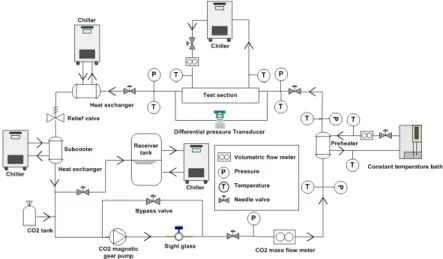
Figure 1 shows a schematic of the experi
mental setup. The test setup was composed of a magnetic gear pump, preheater, test section, sub
cooler, chillers, constant temperature bath, and receiver tank for safety. The working fluid was pure CO 2 , and the secondary fluid for the pre
heater and the test section was an Ethylene Gly
col (EG) and water mixture (brine), with a con
centration of 40% of EG. The CO 2 condensation heat transfer coefficient (hi) was calculated by Eq. (1). The thermal resistance of the microchan
nel wall was neglected in Eq. (1), which was estimated by less than 0.2% compared to that of
fluids. The UA value in Eq. (1) was obtained by using the heat transfer amount from CO 2 to brine, and temperatures of inlets and outlets of CO 2 and brine as shown in Eq. (2). The brineside heat transfer coefficient was determined by utilizing the Wilson Plot method as shown in Eq. (3).
(1)
(1)
(2)
(2)
×
(3)
(3)
Results and discussion Flow visualization
Figure 2 shows the representative images of flow patterns of CO 2 condensation in the narrow channel. The present flow patterns were classi
fied by the following definitions. Bubbly flow : Small bubbles separately flow along channel.
Intermittent flow : Large bubbles from merging small bubbles flow at the center of channel,
[Figure 1] Schematics of experimental setup
설비저널 제 44권 2015년 12월호 95
2015년도 학회상 수상 자료
and liquid-phase CO 2 flows close to wall. The boun daries between bubbles can be found, and boundaries between liquidphase and bubbles are wavy and irregular. Annular flow : Thin liq
uid film is formed at the wall and the shape of liquid film is very steady. Most part of channel is occupied by vaporphase CO 2
Effects of oil on heat transfer coeffici ent and pressure drop
Figure 3 shows the effects of oil concent
ration on CO 2 condensation heat transfer co
effici ent and pressure drop. The heat transfer coefficient significantly decreased with oil con
centration. Decrease of condensation heat trans
fer coefficient with oil addition came from the increased thermal resistance by oil-film at tube wall, which prevents the vapor CO 2 from directly
contacting on tube wall.
Developing new models for conden sa- tion heat transfer coefficient of CO 2
We developed a new model for the conden
sation heat transfer coefficient of CO 2 by al
lowing for the liquid film thickness and smooth interface shape of the liquid film. Eq. (4) shows the present model, and Table 1 shows con
stants in Eq. (4). The nondimensional form of liquid film thickness, the ratio of the Weber number and the Froude number were utilized to
[Figure 2] Flow patterns of CO
2condensation in narrow channel
(a) Bubbly flow (b) Intermittent flow (c) Annular flow
12000
10000 60
K )
Oil concentration Pure CO
20.7 wt.%
1.0 wt.%
1 2 t %
Oil concentration Pure CO
20.7 wt.%
1.0 wt.%
1 2 t % 8000
D
h= 0.68 mm T
cond= 0
OC G = 600 kg/m
2s
ci en t ( W /m
2K 1.2 wt.% 1.2 wt.%
p( kP a)
6000 40
sf er coeff ic essure dro p
4000
Heat tr an Pr e
0.0 0.3 0.6 0.9 1.2
2000
0.0 0.3 0.6 0.9
20
Vapor quality Vapor quality
Vapor quality Vapor quality
[Figure 3] Effects of oil on CO
2condensation heat transfer coefficient and pressure drop
<Table 1> Constants in the present model
Constants Smooth tube Microchannel
a 226.04 19.72
b 0.25 0.43
c 0.75 0.3
d -0.39 -0.31
e -0.3 -0.39
f -0.21 -0.59
10000
Microchannel
ction
-20%
Predic
+20%
1000 10000
1000
20%
E i t
1000