1. 서 론1)
Carbon fiber (CF) is a single, columnar filament with a diameter ranging from 5 to 10 µm, and is composed mostly of carbon atoms
† Corresponding Author: Gyeongsang National University,
Department of Materials Engineering and Convergence Technology, Research Institute for Green Energy Convergence Technology, Jinju 52828, Republic of Korea
Tel: +82-55-772-1657 e-mail: [email protected]
pISSN: 1225-0112eISSN: 2288-4505 @ 2021 The Korean Society of Industrial and Engineering Chemistry. All rights reserved.
[1,2]. In general, CFs are generally employed as reinforcements in structural composites in which CFs are impregnated with polymer matrix. Since the reinforced composites exhibit an unprecedented prop- erty, i.e., lightweight-but-strong characteristics, which can be hardly at- tained from traditional metal parts, they are extensively adopted in var- ious fields of industries, such as aviation, shipbuilding, automobile, civil engineering, and construction, etc[3-6].
Recently, electric vehicles (EVs) are being commercialized, and re- chargeable energy sources such as batteries are used as on-board power sources[7]. In such transportation services, especially, secondary acci-
A Review of Structural Batteries with Carbon Fibers
Dong-Jun Kwon and Sang Yong Nam†
Department of Materials Engineering and Convergence Technology, Research Institute for Green Energy Convergence Technology, Gyeongsang National University, Jinju 52828, Republic of Korea
(Received April 26, 2021; Revised May 24, 2021; Accepted June 4, 2021)
초 록
탄소 섬유 강화플라스틱은 가볍지만 우수한 기계적 강도를 가지는 복합재의 한 종류이다. 가벼우면서 우수한 기계적 강도를 가지는 탄소 섬유 강화플라스틱은 산업 전반에 널리 이용되고 있으며, 최근 활발히 연구되고 있는 전기자동차 및 무인기 등의 무게 감소 핵심 대체 부품으로 연구되고 있다. 배터리를 전원으로 사용하는 운송수단 등은 외부 충격 에 이차 폭발의 위험이 있기 때문에 배터리를 안전하게 보호할 수 있는 덮개가 필수적인 동시에, 무게를 줄여 주행거 리를 늘려야 하는 요구조건을 만족해야 한다. 이러한 요구 조건에 부합하는 재료로 탄소섬유 강화플라스틱이 손꼽히 고 있고, 배터리 보호 덮개 및 다양한 대체품으로의 활용이 연구되고 있다. 한편, 우수한 전기적 특성을 가진 탄소 섬유를 배터리 구성품으로 활용하는 연구가 배터리 분야에서 진행 중이고, 이에 더 나아가 탄소 섬유가 배터리를 보 호하고 배터리 전극 및 집전체 역할까지 동시에 수행하는 구조용 배터리에 대한 연구가 스웨덴과 미국을 중심으로 활발히 연구 중이다. 본 총설에서는 탄소 섬유의 역할에 따른 구조용 배터리의 분류 및 해당 배터리들에서 발생하는 문제점 등을 포괄하는 최근 연구 동향을 요약하고, 구조용 배터리에 대한 전망을 간략히 논의하고자 한다.
Abstract
Carbon fiber reinforced polymer (CFRP) is one of the composite materials, which has a unique property that is lightweight but strong. The CFRPs are widely used in various industries where their unique characteristics are required. In particular, electric and unmanned aerial vehicles critically need lightweight parts and bodies with sufficient mechanical strengths.
Vehicles using the battery as a power source should simultaneously meet two requirements that the battery has to be safely protected. The vehicle should be light of increasing the mileage. The CFRP has considered as the one that satisfies the re- quirements and is widely used as battery housing and other vehicle parts. On the other hand, in the battery area, carbon fibers are intensively tested as battery components such as electrodes and/or current collectors. Furthermore, using carbon fi- bers as both structure reinforcements and battery components to build a structural battery is intensively investigated in Sweden and the USA. This mini-review encompasses recent research trends that cover the classification of structural batteries in terms of functionality of carbon fibers and issues and efforts in the battery and discusses the prospect of structural batteries.
Keywords: Lithium-ion battery, Cathode, Mechanical properties, Carbon fiber, Energy storage, Electrochemical performance
Figure 1. Estimated breakdowns of the vehicle weights for the studied EVs. The components highlighted with bold text corresponds to parts that potentially can be replaced with SBCs. Images from Refs. [15].
dents such as battery explosion due to external impacts should be pre- vented so that heavy-duty protections are being sought to minimize the possibility of the accidents[8,9]. For battery housing, metals are gen- erally used because of their excellent mechanical properties. To secure the high mileage of EVs[10,11], however, metal housings may not be suitable since they have relatively high specific gravities; for example, iron has ~7.86 in specific gravity[12,13]. In contrast, structural compo- sites comprising carbon fibers and plastics have relatively low specific gravities of 1~2, satisfying required mechanical strengths for battery housing[14].
Asp group at Chalmers University of Technology has analyzed how much weight can be reduced by replacing car parts with CF-reinforced composites[16,17]. In their work, two EVs, the Tesla Model S and BMW i3, were selected. Estimated breakdowns of the vehicle weights were listed in the tables of Figure 1[18,19]. From their analysis, in the battery parts vehicle weight reduction can be achieved if metal-based battery pack housing can be replaced with CF-reinforced composite housing[20,21]. Moreover, further vehicle weight reductions of 50% at the most can be attained by making the battery pack integrated with other parts such as battery components, Al space frame, interior, or even exterior[22,23]. This new type of battery is categorized into a structural battery that plays multiple roles as not only a power source but also a structural part in the EVs[24]. Since CF used as reinforce- ment in the car parts consists of > 92% pure carbon and the inter- calation potential of Li into carbon materials is very close to the reduc- tion potential of Li+/Li, CF can serve as a current electrode, battery anode, and even structural bodies of vehicles simultaneously[25]; high carbon content in CF enables to deliver high current density through the structural body and the low-lying potential allows CF to serve as an anode in lithium-ion batteries[26]. Due to this wide range of poten- tial of CF, employing CFs in battery has been drawing great attention, and lots of reports on CFs used as battery components have been made[27,28].
In this mini-review, we would give a brief introduction of structural batteries, including definition, classification, applicability, drawback, and the effort to overcome the shortcomings of structural batteries.
Figure 2. Classification of structural battery: (a) structure-integrated type[29], (b) function-integrated type[30,31].
2. Definition of Structural Battery and Its Classification in Terms of Structure and Functionality
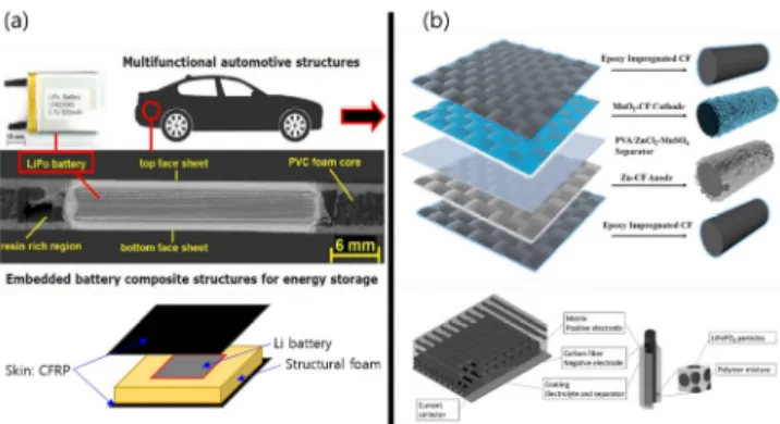
A structural battery is a type of battery that fulfills a load-bearing function[25]. Figure 2 shows structural batteries categorized by struc- ture and functionality; the structure-integrated type contains a full bat- tery (or battery pack) protected by load-bearing composite materials, while the function-integrated type has load-bearing CFs as battery com- ponents working as electrode material, electrode supporter, current col- lector, and battery housing[32].
Pattarakunnan et al. demonstrated a typical structure-integrated type of structural battery, where a pouch cell encapsulated with carbon fi- ber-reinforced polymer (CFRP) composites using a vacuum bag resin infusion (VBRI) process[33,34]. This structure-integrated structural bat- tery consists of CFRP laminate face skins comprising two plies of car- bon fabric (described above) arranged in a [0/90]s pattern, a closed-cell PVC foam (100 kg/m3; Divinycell H100) core with a single rec- tangular-shaped cut-out (40 mm × 30 mm), and a pouch cell placed in the cut-out pocket. With the structural battery, they conducted im- pact tests complying with ASTM D7136. Notably, battery performance was not affected significantly at low impact energies (below 6 J), while higher impact energies over 6 J made the battery malfunction, crushing the internal electrode layers, which caused an internal short circuit [29,33,34]. The results suggest that their structural battery can be de- ployed to vehicles where only a weak impact is tolerated.
The function-integrated type of structural battery embeds multifunc- tional carbon fibers that work as both structural supporters and battery components. Moyer et al. demonstrated a multifunctional battery plat- form where active materials for batteries are combined with CF fabrics to form energy storage composites based on traditional layup methods.
This design utilizes epoxy resin as a battery housing and CFs as both current collector and load-bearing supporter. The schematic illustration of the battery structure is shown in Figure 4[35]. Although battery per- formance is still low compared to that of a conventional pouch cell, mechano-electrochemical performance was greatly improved; for exam- ple, even at 100 MPa of tensile stress full cell capacity and energy density retain a half values of the battery with no stress[36,37].
Figure 4. Carbon fiber battery composite fabrication as shown by SEMs of (a) carbon fiber, (b) graphite, and (c) lithium iron phosphate, (d) a scheme showing the stacking of the individual layers of the composite battery along a picture of these layers cured into a composite material and (e) composite layup process along with a picture of a carbon fiber composite structural battery panel being held[35].
Figure 5. Replacing the interior, external battery pack with structural battery creates free volume within the CubeSat chassis; (a). Electroche- mical performance of 4 composite structural battery panels in series in a 1U prototype CubeSat frame, (b) lighting a LED, and (c) operating a fan[35].
From this approach, space and weight can be significantly saved since the space to store conventional batteries or battery packs can be
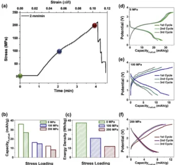
Figure 6. Mechano-electrochemical performance of carbon fiber com- posite battery panels (a) stress-strain curve of tensile testing, (b) charge (outlined bar) and discharge (striped bar) capacity at different stress loadings, (c) energy density at different stress loadings, and galvanostatic charge-discharge curves at stress loadings of (d) 0 MPa, (e) 100 MPa, (f) 200 MPa.
emptied; battery components and other structural parts are integrated into the structural battery architecture (Figure 5).
Importantly, battery performances after load-bearing tests were not recovered (Figure 6), which implies that mechanical stress resulted in permanent deformations and damages on the battery components and interfaces between the components. Those originated from battery stack instability, active material delamination/separation from conducting me- dia or current collectors, impregnation of CFs with electrode materials, etc. In the following sections, issues occurring in the structural bat- teries and the effort to overcome the issues are further discussed[35].
3. Issues and Limits in Structural Batteries and the Effort to Overcome
3.1. Slippage of battery stack in structural battery
In a conventional structure-integrated type of structural battery
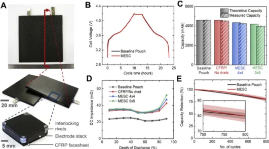
(Figure 7), a pouch cell is simply encapsulated by structural compo- sites without any additional structural supporters, which allows a small mechanical load on the cell to give rise to excessive deformation at a certain point of impact and also leads to slippage between constituent battery layers in a pouch cell. Without the interlayer shear resistance of the battery core, the thin battery layers tend to bend around their own individual neutral axis. The contribution to the structural rigidity of the face sheets will be minimized. Ladpli et al. suggested an ad- vanced structure-integrated type of structural battery (Figure 8). The advanced architecture contains interlocking polymer rivets to stabilize the battery electrode stack mechanically. The interlocking rivets inhibit interlaminar slips between electrode layers, thus facilitating the effec- tive transfer of the shear stress through the battery stack to the CFRP face sheets [Figure 8(c)]. This is analogous to the use of stud shear connectors in civil construction, which can enhance shear interaction and load transfer between concrete and steel parts[39-41]. Thus, these rivets serve as load transfer media between battery layers, allowing constituent battery layers to store electrical energy while also con- tributing to the structural load-bearing performance without any mod- ifications to the battery chemistry. They finally demonstrated versatility and scalability of their advanced design of structural battery by apply- ing the battery architecture to various shapes of structures; Three-cell MESC module in the form of a structural I-beam (5 Wh; 30 cm long, 2.5 cm high) three-cell MESC I-beam module (40 Wh; 38 cm long, 4 cm height), 12-cell MESC triple-webbed I-beam module (240 Wh, 50 cm long, 13 cm height), and 10-cell electric skateboard with
Figure 8. Scaled-up MESC prototypes demonstrating the material's versatility and scalability. A) Three-cell, 5 Wh MESC module in the form of a structural I-beam (30 cm long, 2.5 cm high); B) three-cell, 40 Wh MESC I-beam module (38 cm long, 4 cm high); C) 12-cell, 240 Wh MESC triple-webbed I-beam module (50 cm long, 13 cm high); D) 10-cell, 200 Wh electric skateboard with MESC-integrated deck[38].
MESC-integ- rated deck (200 Wh) (Figure 8). Therefore, the advanced architecture presented an advancement in battery architecture to with- stand external impact, showing significant improvements in mechanical performance over traditional pouch cells in terms of mechanical bend- ing rigidity [Figure 8(b)] and capacity retention upon mechanical fa- tigue cycles [Figure 8(c)]. In the comparison of figures of merit (Figure 8), however, it is found that there are limits of the advanced architecture that has considerably reduced gravimetric and volumetric energy densities compared to a conventional pouch cell, which has to be improved in the future[42].
Figure 7. A) As-fabricated MESC coupon. The cross-sectional view shows the MESC's internal components: the perforated battery core, rivets, CFRP facesheets, and edge-filling frame. The building-block unit cell, with the CFRP replaced by translucent glass-fiber composites, shows the battery stack being constrained by rivets at each corner. B~E) Electrochemical results. B) Charge-discharge voltage curves, where the MESC cells show the unaltered and inherent graphite/NMC chemistry characteristics similar to those of a Baseline Pouch cell; C) apparent capacity, where the MESC's apparent capacity is reduced only very slightly because of its construction as compared with its theoretical capacity; D) DC impedance, where a considerable increase in DC impedance suggests that further development is required on the cell design and fabrication process; E) capacity retention, where the MESC shows excellent capacity retention (80% retention at 800 cycles) similar to that of Baseline Pouch cells. The error bars and shaded areas in C~E) represent the standard deviations of five replicated samples[38].
CFs, CFs are coated with another active material. Although this ap- proach prevented battery failures from the lithiation/delithiation of CFs, other issues occurred; active materials coated on CFs were detached from the surface of the CFs during battery charge and discharge, and the detachment of active materials gave rise to battery failures[50].
To enhance the surface adhesions, Huang et al. treated pristine CFs by heating them in air to remove the sizing agent, turning the pristine CFs into oxidized CFs (OCFs) where oxides from on the surface of CFs. Upon the oxidation process, CF surface gets rich in C=O group, and the surface oxidation may enable better electrochemical deposition of active materials on the OCF scaffolds. Specifically, they employed CFs (T300, 3K) combined with 1 M polysulfide catholyte as a cathode.
During the charge/discharge process, sulfur and Li2S2/Li2S are con- formally electrodeposited onto the OCFs, and robust contacts between active materials and OCFs are achieved (Figure 10). On the anode side, molten lithium is infiltrated into OCF matrix. Although the un- avoidable Li intercalation reduces the mechanical properties of carbon fibers, the excessive lithium metal can act as a glue to bind litigated OCFs together, thereby enhancing the mechanical strength of the
Figure 9. The design principle of electrode-position-like electrodes for structural energy storage. (a) An illustration of the intrinsically low mechanical strength of particle-based planar electrodes, suffering from the delamination of active materials or crack of current (Al or Cu foil) during cycling under collectors deformation. (b) An illustration of the delamination of active materials from carbon fibers during cycling under deformation due to the weak solid-solid interactions. (c) An illustration of the enhanced strength via electrodeposition-like reaction on structural skeleton[50].
anode. Figure 10(f) infers that enhanced adhesions between active materials and the OCF scaffolds resulted in batter battery performance;
the Li/Li symmetric cell with Li/OCF electrodes exhibits a stable voltage profile and a small overpotential of 20 mV over 800 h at the current density of 1.0 mA cm-2. Moreover, even under 20 MPa, the structural battery based on OCF matrices showed little degradation in
Figure 10. (a) The surface morphology of OCF after depositing of Li 2 S. (b) Digital image of a piece of OCF after infiltrating the molten lithium.
(c) The UTS and (d) Young’s modulus of carbon-fiber-rein- forced electrodes in comparison to conventional particle-based elec- trodes. (e) The cycling performance of the polysulfide cathode with pristine CF (black curve) and OCF 500 ℃ 2 h (red curve). (f) The cycling stability of Li/Li symmetric cells with conventional Li foil (black) and Li/OCF composite in b. The current and the deposited capacity are 1.0 mA cm-2 and 1.0 mAh cm-2, respectively. The inset shows the voltage profile at the 150th and 350th cycle[50].
Figure 11. The electrochemical performance of the two cells at various compressive stresses[50].
the battery performance (Figure 11).
Sanchez et al. also demonstrated a stable coating of battery materials on CFs. In their study, they adopted an electrophoretic deposition (EPD). The EPD allows the production of a homogenous coating on large areas of conductive materials in a one-step process [51,52] and can be employed to coat composite materials as well. They used the EPD to assemble a cathodic composite material directly on the surface of CFs. Their study adopted 2-dimensional nanosheets of electrochemically exfoliated graphene oxide (EGO) to connect 3-dimensional LiFePO4 and carbon black (CB) particles. The EGO sheets[53,54], which resemble the role of the oxidation, improve the electrical connectivity and adhesion of the active composite to underlying CFs and provide sufficient surface areas to accommodate the active material (LiFePO4
> 90 wt% loading), which consequently leads to low degradation upon battery cycling and low charge transfer resistance in the structural battery.
To further enhance the structural stability of the structural battery, the matrix mixture needs to be solid or semi-solid[56]. Xu et al. stud- ied adhesion properties of semi-solid matrix mixtures comprising solid polymer phase and liquid electrolyte phase to the surface of CFs[57].
The solid polymer phase provides mechanical robustness of the battery since the polymer phase tightly grabs CFs while liquid electrolytes that are an ion-conducting medium negligibly adhere to CFs. The matrix mixture is schematically depicted in Figure 13. The study used two dif- ferent mixing formulations for matrix mixtures and two different car- bon fiber types (T800H-6k-40 B and T800S-12 k-50C) using different sizing[58,59]. Microbond testing was adopted to investigate adhesive forces between fibers and matrix mixtures. In Figure 13, fiber sizing appears to have little influence on the interfacial adhesion, but a sig- nificant difference in interfacial adhesion was found depending on dif- ferent liquid electrolytes, which could be related to the different mono- mers in the electrolytes. The results suggested that further mechanical robustness of structural batteries can be pursued by employing curable epoxy resins or polymers that tightly adhere to the CFs[60-62].
3.3. Impregnation of CFs with active material matrix
Impregnation of CFs with active materials determines specific ca- pacity and energy density especially when CFs are major current-con- ducting pathways in battery electrodes; where active materials contact
Figure 12. (a) Structural Battery Concept (b) Schematic illustration of EPD synthesis of the LiFePO4/EGO electrode composite (c) Cross Section SEM Images of the LiFePO4/EGO 5 min electrode composite sample deposited on Carbon Fibers (d) The inset of panel shows a zoom-in of the fibers’ surface (e) Specific capacities (normalized over the total electrode mass) of the three samples at various C-rates, exp.
error for each point is +/- 2 mAh.g-1 (f) Cycling stability of the three samples cycled at 1C[55].
Figure 13. Schematic of carbon fibers in a structural battery electrolyte.
Within a structural battery, the carbon fibers are included in a structural battery electrolyte. This matrix material both transfer load between the reinforcing fibers using a percolating network of solid polymer and conduct lithium ions through a network of liquid electrolyte[57].
Figure 14. Average interfacial shear strength values measured for the different fibers and SBE systems, including control samples made with vinyl ester (VE) Error bars represent measurement standard deviations with at least three samples per system[57].
the surfaces of CFs is the actual active areas for current collection.
This approach can greatly enhance specific surface areas of current collectors if a high degree of impregnation can be achieved. Park et al. studied impregnation of woven carbon fabrics (current collector) with electrode slurry, which is composed of LiFePO4, carbon black, PVDF, and NMP[65]. In this study, they used woven carbon fabric as the current collector, and Si rubber and an autoclave were used to im- pregnate woven carbon fabrics with the electrode slurry. Using speci- mens with different thicknesses of electrode slurry, degree of im- pregnation and battery performance was assessed. Although the thick- ness of electrode slurry increases, the degree of impregnation of woven carbon fabrics looks more or less the same; electrode slurry forms a layer with a thickness of 30~80 µm on the woven carbon fabrics for both cases. The poor impregnation may limit the battery capacity de- spite the different thickness of electrode materials. The study about the impregnation of the woven carbon fabrics with the electrode slurry is still in the initial research stage. There is a lot of room to improve the battery performance by controlling types of weaves, the viscosity of electrode slurry, and so forth.
Figure 15. SEM micrographs of the structural batteries’ cross-sections, as indicated by the inscribed box in the schematic. Structural battery cross-sections with (a) Whatman GF/A separator and b) GF plain weave separator. Average thicknesses in the regions depicted in the micrographs: a) CF electrode, 65 µm; Whatman GF/A separator, 185 µm; and positive (LFP) electrode, 50 µm; (b) CF electrode, 125 µm;
GF separator, 70 µm; and positive (LFP) electrode, 50 µm[63], (c) Configuration of vacuum bag for electrode manufacturing and function of the Si rubber[64].
4. Concluding Remarks
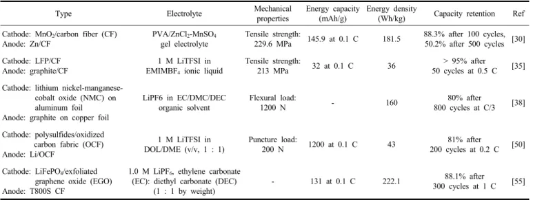
The structural battery is at the intersection of research areas of com- posite material and battery. So far, most works have been done by a few leading groups with research capabilities on both composite mate- rial and battery. As aforementioned, there are various obstacles to overcome for the commercially viable structural battery. Table 1 sum-
Type Electrolyte Mechanical
properties
Energy capacity (mAh/g)
Energy density
(Wh/kg) Capacity retention Ref Cathode: MnO2/carbon fiber (CF)
Anode: Zn/CF
PVA/ZnCl2-MnSO4
gel electrolyte
Tensile strength:
229.6 MPa 145.9 at 0.1 C 181.5 88.3% after 100 cycles, 50.2% after 500 cycles [30]
Cathode: LFP/CF Anode: graphite/CF
1 M LiTFSI in EMIMBF4 ionic liquid
Tensile strength:
213 MPa 32 at 0.1 C 36 > 95% after
50 cycles at 0.5 C [35]
Cathode: lithium nickel-manganese- cobalt oxide (NMC) on aluminum foil
Anode: graphite on copper foil
LiPF6 in EC/DMC/DEC organic solvent
Flexural load:
1200 N - 160 80% after
800 cycles at C/3 [38]
Cathode: polysulfides/oxidized carbon fabric (OCF) Anode: Li/OCF
1 M LiTFSI in DOL/DME (v/v, 1 : 1)
Puncture load:
200 N 1200 at 0.1 C 43 81% after
200 cycles at 0.2 C [50]
Cathode: LiFePO4/exfoliated graphene oxide (EGO) Anode: T800S CF
1.0 M LiPF6, ethylene carbonate (EC): diethyl carbonate (DEC)
(1 : 1 by weight)
- 131 at 0.1 C 222.1 88.1% after
300 cycles at 1 C [55]
Table 1. Mechanical and Electrochemical Performances of Structural Batteries
marizes mechanical and electrochemical performances of structural batteries. Although adding mechanical properties into batteries may re- duce the battery performances, extensive attempts have been tried with various combinations of cathodes, anodes, electrolytes, and structural reinforcements. The issues occurring at either side of research areas and/or at the intersection need to be more openly addressed and tack- led to put together forces to figure out the problems. Moreover, simu- lation works can direct the researchers who conduct their research ex- perimentally to the right solutions and help verify their experimental facts. We hope this review would be a bridge for researchers on both sides or even other research areas to join forces for the commercializa- tion of structural batteries.
Acknowledgment
This research was supported by Basic Science Research Program through the National Research Foundation of Korea (NRF) funded by the Ministry of Education (2020R1A6A1A03038697).
References
1. B. A. Newcomb, Processing, structure, and properties of carbon fi- bers, Compos. Part A Appl. Sci. Manuf., 91, 262-282 (2016).
2. A. A. Jaber, A. A. Obaid, S. G. Advani, and J. W. Gillespie, Pre- diction of equilibrium spacing between charged polymer particles in contact with a carbon fiber, J. Electrostat., 111, 103577 (2021).
3. D. J. Kwon, N. S. R. Kim, Y. J. Jang, H. H. Choi, K. Kim, G.
Kim, J. Kong, S. Y. Nam, Impacts of thermoplastics content on mechanical properties of continuous fiber-reinforced thermoplastic composites, Compos. B Eng., 216, 108859 (2021).
4. D. J. Kwon, J. H. Kim, K. L. DeVries, and J. M. Park, Optimized epoxy foam interface of CFRP/epoxy foam/CFRP sandwich com- posites for improving compressive and impact properties, J. Mater.
Res. Technol., 11, 62-71 (2021).
5. J. H. Kim, P. S. Shin, D. J. Kwon, and J. M. Park, 2D electrical resistance (ER) mapping to detect damage for carbon fiber reinforced polyamide composites under tensile and flexure loading, Compos.
Sci. Technol., 201, 108480 (2021).
6. D. J. Kwon, N. S. R. Kim, Y. J. Jang, S. B. Yang, J. H. Yeum, J. H. Jung, S. Y. Nam, Y. B. Park, and W. Ji, Investigation of im- pact resistance performance of carbon fiber reinforced polypropylene composites with different lamination to applicate fender parts, Compos. B Eng., 215, 108767 (2021).
7. J. Yuan, L. D. Gomba, A. D. Callegaro, J. Reimers, and A. Emadi, A review of bidirectional on-board chargers for electric vehicles, IEEE Access, 9, 51501-51518 (2021).
8. Y. Balai and S. Stegen, Review of energy storage systems for ve- hicles based on technology, environmental impacts, and costs, Renew. Sustain. Energy Rev., 135, 110185 (2021).
9. H. A. Gabbar, A. M. Othman, and M. R. Abdussami, Review of battery management systems (BMS) development and industrial standards, Technol., 9(2), 1-23 (2021).
10. A. Taniguchi, N. Fujioka, M. Ikoma, and A. Ohta, Development of nickel/metal-hydride batteries for EVs and HEVs, J. Power Sources, 100, 117-124 (2001).
11. X. Zeng, M. Li, D. A. E. Hady, W. Alshitari, A. S. A. Bogami, J.
Lu, and K. Amine, Commercialization of lithium battery technologies for electric vehicles, Adv. Energy Mater., 9, 1900161 (2019).
12. S. Kawkita, M. Teranishi, Y. Ishizaka, and K. Fushinobu, Compa- rison between the theoretical, experimental and numerical thermal conductivity of composite thermal interface materials using copper metal foam, 2020 19th IEEE Intersociety Conference on Thermal and Thermomechanical Phenomena in Electronic Systems (ITherm), July 21-23, Orlando, Florida, USA (2020).
13. G. Schuh, G. Bergweiler, F. Fiedler, and M. Koltermann, Flexible production concept of a low-cost battery pack housing for electric vehicles, Procedia CIRP, 93, 137-142 (2020).
14. Z. Wang, H. Zhang, and X. Xia, Experimental investigation on the thermal behavior of cylindrical battery with composite paraffin and fin structure, Int. J. Heat Mass Transf., 109, 958-970 (2017).
15. D. Carlstedt and L. E. Asp, Performance analysis framework for structural battery composites in electric vehicles, Compos. B Eng., 186, 107822 (2020)
16. D. Carlstedt, W. Johannisson, D. Zenkert, P. Linde, and L. Asp.
Conceptual design framework for laminated structural battery com- posites, In: Proc. 18th Eur. Conf. Compos. Mater., Athens, Greece (2018).
17. https://www.chalmers.se/en/staff/pages/leifas.aspx.
18. Tesla model S owner’s manual. Version 2018.48.12. Available on- line: https://www.tesla.com/sites/default/files/model_s_owners_manu- al_north_america_en_us.pdf (2019).
19. BMW. http://www.bmw.com (2019).
20. N. Ihrner, W. Johannisson, F. Sieland, D. Zenkert, and M. Johansson, Structural lithium ion battery electrolytes: Via reaction induced phase-separation, J. Mater. Chem. A, 5, 25652-25659 (2017).
21. Z. Wang, M. Kaferbock, H. Zhao, and H. Chen, First Body-in-white made from composites for a chinese electric car, ATZ Worldwide, 123, 16-21 (2021).
22. J. Duan, X. Tang, H. Dai, Y. Yang, W. Wu, X, Wei, X. Wei, and Y. Huang, Building safe lithium-ion batteries for electric vehicles:
A review, Electrochem. Energy Rev., 3, 1-42 (2020).
23. Y. Miao, P. Hynan, A.V. Jouanne, and A. Yokochi, Current li-ion battery technologies in electric vehicles and opportunities for ad- vancements, Energies, 12, 1074 (2019).
24. Y. Chen, Y. Kang, Y. Zhao, L. Wang, J. Liu, Y. Li, Z. Liang, X.
He, Xing, Li, N. Tavajohi, and B. Li, A review of lithium-ion bat- tery safety concerns: The issues, strategies, and testing standards, J. Energy Chem., 59, 83-99 (2021).
25. L. Asp, M. Johansson, G. Lindbergh, J. Xu, and D. Zenkert, Structural battery composites: A review, Funct. Compos Struct., 1, 042001 (2019).
26. Y. Yang, W. Yuan, X. Zhang, Y. Ke, Z. Qiu, J. Luo, Y. Tang, C. Wang, Y. Yuan, and Y. Huang, A review on structuralized cur- rent collectors for high-performance lithiumion battery anodes, Appl. Energy, 276, 115464 (2020).
27. Y. Wang, X. Wang, M. Xue, Q. Li, Y. Zhang, D. Liu, J. Liu, and W. Rao, All-in-One ENERGISER design: Smart liquid metal-air battery, Chem. Eng. J., 409, 128160 (2021).
28. D. A. Shockey, S. C. Ventura, S. C. Narang, J. W. Simons, B. C.
Bourne, and B. D. Peterson, Power composites: Structural materi- als that generate and store electrical energy, Final Report, DTIC (2005).
29. J. Galos, A. S. Best, and A. P. Mouritz, Multifunctional sandwich
8, 91-95 (2004).
33. K. Pattarakunnan, J. Galos, R. Das, and A. P. Mouritz, Impact dam- age tolerance of energy storage composite structures containing lithium-ion polymer batteries, Compos. Struct., 267, 113845 (2021).
34. J. Galos, A. A. Khatibi, and A. P. Mouritz, Vibration and acoustic properties of composites with embedded lithium-ion polymer bat- teries, Compos. Struct., 220, 677-686 (2019).
35. K. Moyer, C. Meng, B. Marshall, O. Assal, J. Eaves, D. Perez, R.
Karkkainen, L. Roberson, and C. L. Pint, Carbon fiber reinforced structural lithium-ion battery composite: Multifunctional power in- tegration for CubeSats, Energy Storage Mater., 24, 676-681 (2020).
36. S. Arepalli and P. Moloney, Engineered nanomaterials in aerospace, MRS Bull., 40, 804-811 (2015).
37. J. A. Samareh and E. J. Siochi, Systems analysis of carbon nano- tubes: Opportunities and challenges for space applications, Nano- technol., 28, 372001 (2017).
38. P. Ladpli, R. Nardari, F. Kopsftopoulos, and F. K. Chang, Multi- functional energy storage composite structures with embedded lith- ium-ion batteries, J. Power Sources, 414, 517-529 (2019).
39. R. Johnson and I. May, Partial-interaction design of composite beams, Struct. Eng., 53(8), 305-311 (1975).
40. I. M. Viest, Investigation of stud shear connectors for composite concrete and steel T beams, J. Proc., 52, 875-892 (1956).
41. Y. Wang, Deflection of steel-concrete composite beams with parti- al shear interaction, J. Struct. Eng., 124(10), 1159-1165 (1998).
42. E. Jacques, M. He. Kjell, D. Zenkert, G. Lindberghb, and M. Behm, Expansion of carbon fibres induced by lithium intercalation for structural electrode applications, Carbon, 59, 246-254 (2013).
43. L. E. Asp and E. S. Greenhalgh, Structural power composites, Compos. Sci. Technol., 101, 41-61 (2014).
44. J. F. Snyder, R. H. Carter, and E. D. Wetzel, Electrochemical and mechanical behavior in mechanically robust solid polymer electro- lytes for use in multifunctional structural batteries, Chem. Mater., 19, 3793-3801 (2007).
45. T. Carlson, D. Ordeus, M. Wysocki, and L. E. Asp, Structural ca- pacitor materials made from carbon fibre epoxy composites, Compos. Sci. Technol., 70(7), 1135-1140 (2010).
46. N. Muralidharan, E. Teblum, A. S. Westover, D. Schauben, A.
Itzhak, M. Muallem, G. D. Nessim, and C. L. Pint, Carbon nanotube reinforced structural composite supercapacitor, Scientific. Reports, 8, 17662 (2018).
47. W. Johannisson, N. Ihrner, D. Zenkert, M. Johansson, D. Carlstedt, L. E. Asp, and F. Sieland, Multifunctional performance of a carbon fiber UD lamina electrode for structural batteries, Compos. Sci.
Technol., 168, 81-87 (2018).
48. C. Meng, N. Muralidharan, E. Teblum, K. E. Moyer, G. D. Nessim, and C. L. Pint, Mechanically-robust structural lithium-sulfur bat-
and H. M. Cheng, Field emission of single-layer graphene films prepared by electrophoretic deposition, Adv. Mater., 21, 1756-1760 (2009).
52. M. Diba, A. G. Gallastegui, R. N. Klupp Taylor, F. Pishbin, M.
P. Ryan, M. S. P. Shaffer, and A. R. Boccaccini, Quantitative eval- uation of electrophoretic deposition kinetics of graphene oxide, Carbon, 67, 656-661 (2014).
53. Z. Y. Xia, D. Wei, E. Anitowska, V. Bellani, L. Ortolani, V.
Morandi, M. Gazzano, A. Zanelli, S. Borini, and V. Palermo, Elec- trochemically exfoliated graphene oxide/iron oxide composite foams for lithium storage, produced by simultaneous graphene reduction and Fe(OH)3 condensation, Carbon, 84, 254-262 (2015).
54. Z. Y. Xia, M. Christian, C. Arbizzani, V. Morandi, M. Gazzano, V. Quintano, A. Kovtun, V. Palermo, and A robust, modular ap- proach to produce graphene-MO X multilayer foams as electrodes for li-ion batteries, Nanoscale, 11, 5265-5273 (2019).
55. J. S. Sanchez, J. Zu, Z. Xia, J. Sun, L. E. Asp, and V. Palermo, Electrophoretic coating of LiFePO4/graphene oxide on carbon fi- bers as cathode electrodes for structural lithium ion batteries, Compos. Sci. Technol., 208, 108768 (2021).
56. Y. Yu, B. Zhang, M. Feng, G. Qi, F. Tian, Q. Feng, J. Yang, and S. Wang, Multifunctional structural lithium ion batteries based on carbon fiber reinforced plastic composites, Compos. Sci. Technol., 147, 62-70 (2017).
57. J. Xu, W. Johannisson, M. Johansen, F. Liu, D. Zenkert, G.
Lindbergh, and L. E. Asp, Characterization of the adhesive proper- ties between structural battery electrolytes and carbon fibers, Compos.
Sci. Technol., 188, 107962 (2020).
58. Toray Carbon Fibres America Inc., T800H Data Sheet (2019).
59. Toray Carbon Fibres America Inc., T800S Data Sheet (2019).
60. N. Ihrner, W. Johannisson, F. Sieland, D. Zenkert, and M. Johansson, Structural lithium ion battery electrolytes: Via reaction induced phase-separation, J. Mater. Chem. A, 5, 25652-25659 (2017).
61. W. Johannisson, N. Ihrner, D. Zenkert, M. Johansson, D. Carlstedt, L. E. Asp, and F. Sieland, Multifunctional performance of a carbon fiber UD lamina electrode for structural batteries, Compos. Sci.
Technol., 168, 81-87 (2018).
62. L. M. Schneider, N. Ihrner, D. Zenkert, and M. Johansson, Bicon- tinuous electrolytes via thermally initiated polymerization for struc- tural lithium ion batteries, ACS Appl. Energy Mater., 2, 4362-4369 (2019).
63. L. E. Asp, K. Bouton, D. Carlstedt, S. Duan, R. Harnden, W.
Johannisson, M. Johansen, M. K. G. Johansson, G. Lindbergh, F.
Liu, K. Peuvot, L. M. Schneider, J. Xu, and D. Zenkert, A struc- tural battery and its multifunctional performance, Adv. Energy Sustain. Res., 2, 2000093 (2021).
64. H. W. Park, M. S. Jang, J. S. Choi, J. Pyo, and C. G. Kim, Cha-
racteristics of woven carbon fabric current collector electrodes for structural battery, Compos. Struct., 256, 112999 (2021).
65. H. Cha, J. Kim, Y. Lee, J. Cho, and M. Park, Issues and chal- lenges facing flexible lithiumion batteries for practical application, Small, 14(43), 1-18 (2018).
66. H. J. Peng, J. Q. Huang, X. B. Cheng, and Q. Zhang, Review on high-loading and high‐energy lithium-sulfur batteries, Adv. Energy Mater., 7(24), 1700260 (2017).
Authors
Dong-Jun Kwon; Ph.D., Research Assitant Professor, Department of Materials Engineering and Convergence Technology, Research Institute for Green Energy Convergence Technology, Gyeongsang National University, Jinju 52828, Republic of Korea; rorrir@empas.
com, [email protected]
Sang Yong Nam; Ph.D., Professor, Department of Materials Engineering and Convergence Technology, Research Institute for Green Energy Convergence Technology, Gyeongsang National University, Jinju 52828, Republic of Korea; [email protected]

![Figure 11. The electrochemical performance of the two cells at various compressive stresses[50].](https://thumb-ap.123doks.com/thumbv2/123dokinfo/5023435.308735/6.892.479.812.129.652/figure-electrochemical-performance-cells-various-compressive-stresses.webp)