• 검색 결과가 없습니다.

A Convergence Study on the Effects of NH<sub>3</sub>/NOx Ratio and Catalyst Type on the NOx Reduction by Urea-SCR System of Diesel Engine

N/A
N/A
Protected

Academic year: 2021

Share "A Convergence Study on the Effects of NH<sub>3</sub>/NOx Ratio and Catalyst Type on the NOx Reduction by Urea-SCR System of Diesel Engine"

Copied!
8
0
0

로드 중.... (전체 텍스트 보기)

전체 글

(1)

1. Introduction

High thermodynamic efficiency and high fuel economy of diesel engines compared to its gasoline

counterpart have proliferated worldwide research as means to reduce Carbon Dioxide(CO

2

) emissions.

However, direct fuel injection to achieve auto ignition which achieve the high thermal efficiency result in

A Convergence Study on the Effects of NH 3 /NOx Ratio and Catalyst Type on the NOx Reduction by Urea-SCR System of Diesel Engine

Heung-Soo Yoon 1 , Yeon-Seung Ryu 2*

1

Ph.D. Student, Dept. of Security and Management Engineering, Graduate School, Myongji University

2

Professor, Dept. of Security and Management Engineering, Graduate School, Myongji University

디젤엔진의 Urea-SCR 시스템에 의한 NH 3 /NOx 비율 및 촉매 방식이 NOx 저감에 미치는 영향에 관한 융합연구

윤흥수

1

, 류연승

2*

1명지대학교 대학원 보안경영공학과 박사과정, 2명지대학교 대학원 보안경영공학과 교수

Abstract Diesel engines have important advantages over its gasoline counterpart including high thermal efficiency, high fuel economy and low emissions of CO, HC and CO

2

. However, NOx reducing is more difficult on diesel engines because of the high O

2

concentration in the exhaust, marking general three way catalytic converter ineffective.

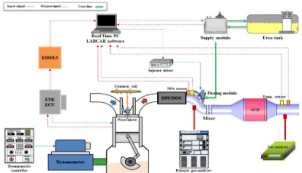
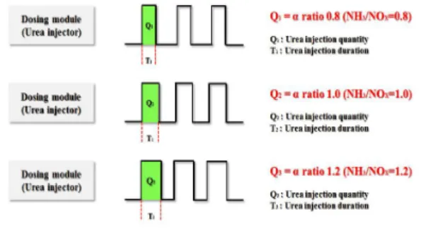
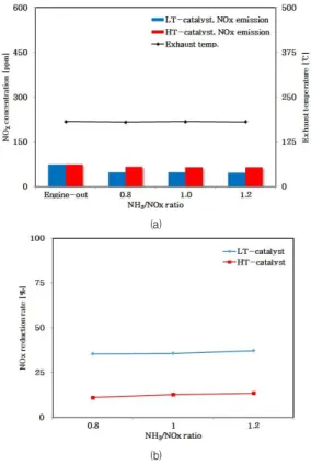
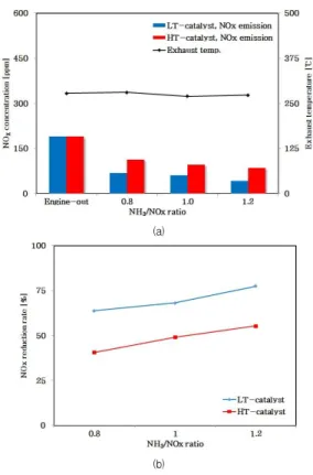
Two method available technologies for continuous NOx reduction onboard diesel engines are Urea-SCR and LNT. The implementation of the Urea-SCR systems in design engines have made it possible for 2.5l and over engines to meet the tightened NOx emission standard of Euro-6. In this study, we investigate the characteristics of NOx reduction with respect to engine speed, load, types of catalyst and the NH

3

/NOx ratio and present the conditions which maximize NOx reduction. Also we provide detailed experimental data on Urea-SCR which can be used for the preparation for standards beyond Euro-6.

Key Words : Selective Catalytic Reduction(SCR), Ammonia(NH

3

), Cu-CHA catalysts, Cu-ZSM-5 catalysts, Euro-6

요 약 디젤엔진은 열효율이 높고 연비가 좋으며 CO, HC 및 CO

2

의 배출량이 낮은 등 가솔린 엔진보다 상당한 장점이 있다. 그러나 디젤엔진은 배기가스 중에 O

2

농도가 높기 때문에 NOx 저감이 어렵고, 삼원촉매를 적용하기 어렵다. Urea-SCR과 LNT는 디젤엔 진에서 NOx를 연속적으로 저감하는데 활용 가능한 두 기술이다. 디자인 엔진에 Urea-SCR 시스템을 구현함으로써 2.5l 이상 엔진 에서 Euro-6의 강화된 NOx 기준을 충족시킬 수 있게 되었다. 본 연구에서는 엔진 회전속도, 부하, 촉매 방식 및 NH

3

/NOx 비율에 따른 NOx 저감 특성을 연구하여 NOx 저감을 극대화하는 조건을 제시하고자 한다. 또한 Euro-6 이상의 규제에 대응할 수 있도록 Urea-SCR에 대한 정밀한 실험 데이터를 제공하고자 한다.

주제어 :선택적 환원 촉매(SCR), 암모니아(NH

3

), Cu-CHA 촉매, Cu-ZSM-5 촉매, 유로-6

*This paper is written based on the master's thesis of the first author.

*Corresponding Author : Yeon-Seung Ryu([email protected]) Received January 9, 2019

Accepted April 20, 2019

Revised February 21, 2019 Published April 28, 2019

(2)

non-uniform distribution of air-fuel ratio, namely higher air-fuel ratio near the injector while lower air-fuel ratio elsewhere. Such non-uniform distribution of air-fuel ratio result in adverse consequences since fuel rich combustion result in the generation of Particulate Matter(PM) while fuel lean combustion result in the generation of Nitric Acids(NOx)[1,2].

Therefore, to alleviate these problems after treatment devices such as Diesel Oxidation Catalyst(DOC), Diesel Particulate Filter(DPF), Selective Catalytic Reduction(SCR), Lean NOx Trap(LNT) etc. have been implemented. Despite tightened Euro-6 emission regulations, the use of conventional in-cylinder control method and Catalyzed Diesel Particulate Filter(CDPF) meet the PM regulation since the allowed total PM weight have not changed and the acceptable PM concentration is only up to 6×10

11

#/km. Unfortunately, the NOx emissions regulation have tightened by 58% to 0.08g/km compared to the Euro-5 standards which makes it necessary for virtually all diesel vehicles to implement some form of an after treatment system such as Urea-SCR or LNT[3-6].

SCR system can be divided into two groups depending on the reducing agents used: HC-SCR use Hydro Carbon(HC) and Urea-SCR use Ammonia(NH

3

), respectively. HC-SCR systems are simple and cost effective since it uses HCs which is already in the exhaust gas itself to reduce NOx emissions without any additives. However, due to relatively low content of the reducing agent and short catalytic reaction interval NOx reduction efficiency is low and is only used in smaller displacement volumes. Unlike HC-SCR, Urea-SCR use urea aqueous solution, namely ‘AdBlue’

during the in-cylinder control process to selectively convert urea(CO

2

(NH

2

)

2

) to NH

3

and reduce NOx emissions in the process. Relatively high NOx reduction efficiency compared to HC-SCR systems resulted in wide use for commercial vehicles such as buses and trucks but the need to equip a storage tank for the urea and a dose control unit increase the complexity and the cost of the system[7,8]. For both

systems mentioned above, it was found that the SCR reduction rate is a function of temperature of the exhaust, space velocity, NH

3

/NOx ratio, NO

2

/NO ratio and such conditions should be controlled for optimal performance[9-11]. According to previous research, EGR+Urea-SCR system achieved NOx reduction efficiency of 73% through the NEDC mode and Cu-CHA SCR catalysts had high NOx reduction at low temperatures are in the range of 423.15 to 573.15K[12].

In this study, the NOx reduction performance was compared for the low and high temperature responsive catalyst to select appropriate catalyst in the low temperature range of emission gas because the conventional Cu-ZSM-5 catalyst has high NOx reduction rate in high temperature, but has an issue of emitting NOx in low temperature while the technology of combustion in low temperature had been adopted recently to reduce the thermal NO. Therefore, both catalysts were compared by establishing Urea-SCR on 2.2l diesel engine adopted low and high pressure Exhaust Gas Recirculation(EGR) type. The test was made under the engine speed and load conditions in driving range mostly used in NEDC-2000 base. The amount of the reductant was set in 0.8 and 1.2 for less and more injection amount respectively on the basis of NH

3

/NOx=1:1.

2. Experimental Setup

The engine adopted here satisfied the emission

regulations of Euro-5a in 2.2l turbo charger common

rail direct injection system mounted on the passenger

car. The Dual-Loop EGR type adopted both of the high

pressure EGR emitting from the front part of the turbo

charger and low pressure EGR extracting the filtered

emission gas passed through CDPF. The diesel engine

used here is a 2.2l Common Rail Direct Injection

engine(CRDI) and the detail image and the specification

is shown in Table 1.

(3)

Item Specification

Type 4 stroke DOHC, CRDI

Number of cylinders 4

Bore 85.0mm

Stroke 96.0mm

Displacement volume 2199cc

Compression ratio 16:1

Firing order 1-3-4-2

Table 1. Specification of the 2.2l Common Rail Direct Injection(CRDI) engine

Only CDPF was mounted originally on the after treatment system of the engine, but the Urea-SCR system designed based on the precedent studies was established additionally. As seen from the exhaust layout installation in engine test bench in Fig. 1.

Fig. 1. The photograph of the exhaust layout installation in engine test bench

The sensors for the emission gas temperature and NOx were installed at the front and back of the catalyst. The emission gas temperature sensor provided the signal for injecting the reductant when the measured temperature was higher than 473.15K. The NOx sensor detected the NOx emitting amount from the emitted gas before and after the catalyst reaction, and decided the NH

3

/NOx ratio from the data feedback.

In addition, the supply module was installed to inject the urea water into the exhausting manifold and to supply the urea aqueous solution from the tank with dosing module. The injection pressure of the dosing module was kept in 9bar consistently. The ETK-ECU was used to control the parameters required for Urea-SCR system controlling. The parameters inside

ETK-ECU were into the PC in real time in use of ES910.3. ES910.3 was linked in connector type between ECU and real time PC. The control parameters inside the ETK-ECU was delivered to real time PC in real time. The real time PC was controlled with LABCAR for real time checking and its operation was observed.

The real time PC controlled the urea aqueous solution injector by integrating the parameters of ETK-ECU and signals from the emission gas temperature sensor and NOx sensor. The controlling algorithm was made by using Matlab/Simulink. The output data was designed from the signal controlling the urea aqueous solution injector by inputting the formula calculating the NH

3

/NOx ratio from the input data of fuel injection amount, emission gas volume, NOx emission amount and emission gas temperature required for controlling.

As seen from the schematic in Fig. 2.

Fig. 2. Schematic diagram of Urea-SCR system in engine bench test

Zeolite series, Cu-ZSM-5 and Cu-CHA catalysts

were used for the experiment. The total capacity of

both catalyst was 2.47l by connecting two filters in size

of diameter 5.66inch×depth 3inch with cell density of

400Cell Per Square Inch(CPSI). The carrier capacity in

consideration of porosity 81% was 2.0l. The catalysts

were made by mounting inside the metal housing. The

catalysts equipped in this study is a zeolite based

which incorporates both Cu-ZSM-5 and Cu-CHA and

the detailed photographs are shown in Fig. 3 and Table

2, respectively.

(4)

Fig. 3. The photograph of the canning zeolite based Cu-ZSM-5 catalysts and Cu-CHA catalysts

Item Specification

Type Cu-ZSM-5 Cu-CHA

Light-off temperature50 459.15K 488.15K

Diameter 5.66inch

Cell density 400cpsi

Dry gain 100-120g/l

Table 2. Specification of catalysts

The engine speed and the load condition was made by using the eddy current dynamometer which generated the torque from the eddy current electromagnetic field. It was operated for 3minutes per experiment by stabilizing for 30seconds after engine start and collecting the data for 2minutes and 30minutes. An engine dynamometer is used to vary the load on the engine and the detailed photograph and the specifications are shown in Table 3.

Item Specification

Absorption power 250kW

Absorption torque 45kg×m

Maximum revolution 9,000rpm

Table 3. Specifications of the eddy current dynamometer

3. Experimental Procedure

The engine speed and the load in terms of Brake Mean Effective Pressure(BMEP) are listed in Table 4 along with the types of catalyst and the NH

3

/NOx

ratios used in this study. The engine speed and the load are selected to reflect the most frequent driving conditions used based on NEDC-2000 driving condition which is the standard for most emission tests. The EGR device used in this study is a Dual-Loop EGR which incorporate both low pressure route EGR and high pressure route EGR conforming to the Euro-5a emissions standard. Zeolite based high temperature Cu-ZSM-5(HT) and low temperature Cu-CHA(LT) catalysts were used. The NH

3

/NOx ratio is defined as the ratio between NH

3

and NOx in this study and it was varied from 0.8 to 1.2 based on previous experimental studies available at the time[13-15]. The experiment was repeated for 5times and its average was shown for the result.

Engine speed (rpm)

Load (bmep)

Catalyst type

NH

3

/NOx ratio

EGR system

Coolant temp.

(°C)

1,500 4

Cu-ZSM-5 Cu-CHA

0.8 1.0

1.2 Dual-Loop

EGR 85±2

8

2,000 4 0.8

1.0 8 1.2

Table 4. The experimental condition

The urea used in this study satisfies AUS 32.5 and the specification is shown in Table 5.

Item Specification

Contents(wt. %) 31.8∼33.2

Density(kg/m

3

) 1,087.0∼1,093.0 Water insoluble matter

(wt. ppm) ≤20

Alkalinity(wt. ppm) ≤2,000

Biuret(wt. %) ≤0.3

Aldehyde(wt. ppm) ≤5

Phosphate(wt. ppm) ≤0.5

Ca(wt. ppm) ≤0.5

Zn(wt. ppm) ≤0.2

Cr(wt. ppm) ≤0.2

Cu(wt. ppm) ≤0.2

Fe(wt. ppm) ≤0.5

K(wt. ppm) ≤0.5

Mg(wt. ppm) ≤0.5

Na(wt. ppm) ≤0.5

Ni(wt. ppm) ≤0.2

Al(wt. ppm) ≤0.5

Table 5. Specifications of the urea aqueous solution

(5)

The NH

3

/NOx ratio here is the ratio between NH

3

and NOx which is normally 1.0 for standard operation but can be controlled to be higher or lower. Higher NH

3

/NOx ratio means that there is more NH

3

for the reduction process but the excess can cause environmental and health problems. Lower NH

3

/NOx ratio means the opposite thus less NOx reduction efficiency is expected. The NH

3

/NOx ratio was varied by modulating the duration of injection of the dosing module as shown in the schematic in Fig. 4. However, the injection frequency was kept constant to 1Hz and the injection pressure was kept constant at 9bars.

Fig. 4. The schematic diagram showing how the NH

3

/NOx ratio is controlled by modulating the urea injection duration

The quantity of injection used for a particular NH

3

/NOx ratio was predetermined using a series of experiments which measured the amount of injection as a function of injection duration which is then curve fitted for calculation of the NH

3

/NOx ratio. A sample experimental result and the curve fit is shown in Fig. 5.

Fig. 5. The sample experiment and curve fit used to determine the NH

3

/NOx ratio with respect to injection duration which is used to predetermine the injection quantity

4. Results and Discussion

The NOx concentration and the NOx reduction rate for different types of catalyst under varies operating conditions is shown in Fig. 6–9. For each of the operating condition the figures show that the NOx concentration reduction is more prominent for the Urea-SCR system with LT-catalyst and produce less overall NOx emission. At engine speed of 1,500rpm and bmep of 4 bars the temperature of the exhaust is approximately 451.15 K and the NOx reduction rate is found to be up to 35% for LT-catalyst but it drops to 23% for the HT-catalyst. From this result it can be concluded that the temperature of the exhaust does not reach the activation temperature of the HT-catalyst therefore shows lower performance compared to its low temperature counterpart.

(a)

(b)

Fig. 6. Variation of (a) NOx concentration and (b)

NOx reduction rate for LT-catalyst and HT-

catalyst for the Urea-SCR system in

Dual-Loop EGR CRDI engine. The operating

conditions were as follows: engine speed

was 1,500rpm, bmep was 4bars, and the

coolant temperature was 85±2°C

(6)

However, when bmep is increased to 8bars keeping the engine speed the same, the exhaust temperature shows an increase of nearly 373.15K compared to that of 4bars. Although the NOx reduction rate is approximately 6% below the LT-catalyst, At such conditions, the results show that the NOx reduction rate of HT-catalyst jumps to 59% indicating that the activation temperature of HT-catalyst have been reached.

(a)

(b)

Fig. 7. Variation of (a) NOx concentration and (b) NOx reduction rate for LT-catalyst and HT- catalyst for the Urea-SCR system in Dual-Loop EGR CRDI engine. The operating conditions were as follows: engine speed was 1,500rpm, bmep was 8bars, and the coolant temperature was 85±2°C

When the engine speed is increased to 2,000rpm the effect of bmep change from 4 to 8bars is identical to the previously mentioned engine speed of 1,500rpm for which increase in the NOx reduction rate is observed for HT-catalyst due to increase in the exhaust

temperature. However, the results indicated that at the same operating conditions, the NOx reduction rate for HT-catalyst at engine speed of 2,000rpm is approximately 11% lower than that of 1,500rpm. This is due to the fact that as the engine speed increases, the flow rate of the exhaust gas increases which in turn increases the space velocity.

(a)

(b)

Fig. 8. Variation of (a) NOx concentration and (b) NOx reduction rate for LT-catalyst and HT- catalyst for the Urea-SCR system in Dual-Loop EGR CRDI engine. The operating conditions were as follows: engine speed was 2,000rpm, bmep was 4 bars, and the coolant temperature was 85±2°C

When the space velocity increases, it reduces the transit time within the catalyst reaction chamber resulting in lower NOx reduction rate. On the contrary, for the LT-catalyst, the NOx reduction rate is relatively unaffected by the variation of engine speed.

Such result shows that the NOx reduction rate of the

LT-catalyst is less sensitive to space velocity

(7)

compared to that of the HT-catalyst.

It was efficient to set the NH

3

/NOx ratio for 0.8 because the NOx reduction rate was not changed as the ratio changed from 0.8 to 1.2 under the engine load in 4 bar in both of the catalysts. It was efficient to set it for 1.2 as the NOx reduction rate was increased from 0.8 to 1.2 under the engine load in 8bar.

(a)

(b)

Fig. 9. Variation of (a) NOx concentration and (b) NOx reduction rate for LT-catalyst and HT- catalyst for the Urea-SCR system in Dual-Loop EGR CRDI engine. The operating conditions were as follows: engine speed was 2,000rpm, bmep was 8bars, and the coolant temperature was 85±2°C

5. Conclusion

1) At the temperature of the exhaust is approximately 451.15K, the NOx reduction rate is found to be up to 35% for LT-catalyst but it drops to 23% for the HT-catalyst.

2) When bmep is increased to 8bars keeping the

engine velocity the same, the NOx reduction rate of HT-catalyst jumps to 59%.

3) The NOx reduction rate for HT-catalyst at engine speed of 2,000rpm is approximately 11%

lower than that of 1,500rpm.

4) The NOx reduction rate of the LT-catalyst is less sensitive to space velocity compared to that of the HT-catalyst.

5) It was efficient to set it for 0.8 as the NOx reduction rate was increased from 0.8 to 1.2 under the engine load in 4bar.

6) It was efficient to set it for 1.2 as the NOx reduction rate was increased from 0.8 to 1.2 under the engine load in 8bar.

REFERENCES

[1] John. B. Heywood. (1998). Internal Combustion Engine Fundamentals, 491-566. McGraw-Hill.

[2] Kraftfahrt-Bundesamt(KBA). (2008). Fuel consumption in MNEDC, at least EU4 certification.

[3] S. Jung & W. Yoon. (2008). Modeling of NH

3

-SCR Diesel NOx Reduction and Effects of NO

2

/NOx, NH

3

/NO Ratio on the DeNOx Efficiency. Transactions of KSAE, 16,(3), 179-187.

[4] D. Chatterjee, T. Burkhardt, T. Rappe, A.Guthenke & M.

Weibel. (2008). Numerical Simulation of DOC+DPF+SCR Systems: DOC Influence on SCR Performance. SAE 2008-01-0867.

[5] G. Madia, M. Manfred, M. Elsener & A. Wokaun. (2002).

The Effect on an Oxidation Precatalyst on the NOx Reduction by Ammonia SCR. Ind. Eng. Chem. Res.

41(15), 3512-3517.

[6] B. Yun, C. Kim, M. Kim, G. Cho, H. Kim & Y. Jeong.

(2010). Numerical Modeling of Vanadia-based Commercial Urea-SCR plus DOC Systems for Heavy-duty Diesel Exhaust Aftertreatment Systems.

Transactions of KSAE, 18(2), 24-30.

[7] Dieter H. E. Seher, Michael Reichelt & Stefan Wickert.

(2003). Control Strategy for NOx - Emission Reduction with SCR. SAE 2003-01-3362.

[8] L. Sharifian, Y. M. Wright & K. Boulouchos. (2011).

Transient simulation of NOx reduction over a

Fe-Zeolite catalyst in an NH

3

-SCR system and study of

the performance under different operating conditions.

(8)

SAE 2011-01-2084.

[9] G. R. Chandler, B. JCooper, J. P. Harris, J. E. Thoss, A. Uusimäki, A. P. Walker & J. P. Warren. (2000). An Integrated SCR and Continuously Regenerating Trap System to Meet Future NOx and PM Legislation. SAE 2000-01-0188.

[10] A. Herman, M. C. Wu, D. Cabush & M. Shost. (2009). Model Based Control of SCR Dosing and OBD Strategies with Feedback from NH

3

Sensors. SAE 2009-01-0911.

[11] J. Hu, Y. Zhao, Y. l. Zhang, S. Shuai, J. X. Wang, T.

Chen & Z. Chen. (2011). Development of Closed-loop Control Strategy for Urea-SCR Based on NOx Sensors.

SAE 2011-01-1324.

[12] J. S. Lee & N. Y. Kim. (2008). Characterization of SCR System for NOx Reduction of Diesel Engine (Ⅱ).

Transactions of KSPE, 25(11), 83-89.

[13] Y. J. Cha. (2013). An Experimental Study on NOx Reduction Characteristics using Zeolite Based Catalyst. Kookmin Univ..

[14] M. J. Song. (2013). A Numerical Analysis on NH

3

Flow Uniformity  Depending on the Changes In shape a Diffuser and Mixer. Kookmin Univ.

[15] H. J. Kim. (2014). An Experimental Study on Charateristics of NOx Reduction with Urea-SCR System depending on EGR Type and α ratio in Passenger Diesel Engine. Kookmin Univ.

윤 흥 수(Yoon, Heung Soo) [정회원]

․2015년 8월 : 국민대학교 자동차산 업대학원 자동차공학과 (석사)

․2018년 3월 ∼ 현재 : 명지대학교 보안경영공학과 (박사과정)

․관심분야 : 무기체계 보안, 방산기 술 보호, 내연기관

․E-Mail : [email protected]

류 연 승(Ryu, Yeon Seung) [정회원]

․1990년 2월 : 서울대학교 계산통계 학과 (학사)

․1992년 2월 : 서울대학교 전산과학 과 (석사)

․1996년 8월 : 서울대학교 전산과학 과 (박사)

․2003년 3월 ∼ 현재 : 명지대학교 컴퓨터공학과 교수

․관심분야 : 시스템 보안, 무기체계 보안, 방산기술 보호

․E-Mail : [email protected]

수치

Fig.  2.  Schematic  diagram  of  Urea-SCR  system  in  engine  bench  test
Fig.  3.  The  photograph  of  the  canning  zeolite  based  Cu-ZSM-5  catalysts  and  Cu-CHA  catalysts
Fig.  4.  The  schematic  diagram  showing  how  the  NH 3 /NOx  ratio  is  controlled  by  modulating  the  urea  injection  duration
Fig.  7.  Variation  of  (a)  NOx  concentration  and  (b)  NOx  reduction rate  for  LT-catalyst and HT-  catalyst  for  the  Urea-SCR  system  in  Dual-Loop  EGR  CRDI  engine
+2

참조

관련 문서

Also, based on the measured NO 2 /NO x ratio data, a mathematical model was proposed to predict the NO 2 /NO x ratio at SCR catalyst, and the suitability of the model

binder was added, the worse the NOx reduction performance was, which was considered to be that the number of active sites of the prepared catalyst surface was occupied by