Smart Device Based Localization for Ship Block Logistics
Kwon-Soo Song
†, Sangdon Lee
††, Doo-Yeoun Cho
†††ABSTRACT
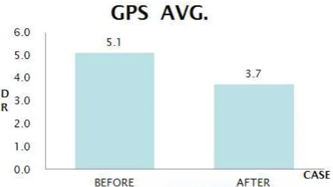
In a ship block logistics application, acquisition of locations is required in order to identify location of the ship blocks. A Smart device equipped with a GPS sensor can be used as a mobile client for a ship block logistics application. However the precision of GPS components on a commercial smart device is not high enough. Therefore, using the GPS for localization may produce significant positioning errors in a ship block logistics system. This paper proposes a method to reduce errors in measuring locations using a smart device. Based on the knowledge of how the location information is used in a ship block logistics application, and the predictability of the client’s moving line based on geographical layout of a shipyard area, our proposed technique enables a better prediction of the ship blocks location.
Performance evaluation shows that the proposed technique can significantly reduce the positional error.
Key words: Shipbuilding, Ship Block Logistics, GPS, Smart Device, Localization
※ Corresponding Author : Doo-Yeoun Cho, Address : (534-729) 61 Dorim-Ri, Chunggye-Myeon, Muan-Gun, Jeonnam, 534-729, TEL : +82-61-450-2769, FAX : +82- 61-452-7774, E-mail : [email protected]
Receipt date : Oct 12, 2012, Revision date : Oct. 24, 2012 Approval date : Oct. 26, 2012
†††
Dept. of Multimedia Engineering, Mokpo National University, Korea
(E-mail: [email protected])
†††
Dept. of Multimedia Engineering, Mokpo National University, Korea
(E-mail: [email protected])
†††
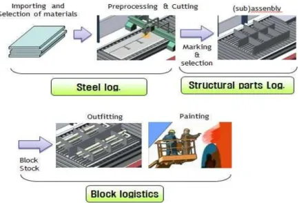
![Fig. 2. A ship block logistics systemblock [3].](https://thumb-ap.123doks.com/thumbv2/123dokinfo/4776096.518535/3.892.146.757.851.1099/fig-a-ship-block-logistics-systemblock.webp)