Vol. 19, No. 9 pp. 13-19, 2018
Effects of MWCNT type and flow type on the electrical conductivity of polycarbonate/MWCNT nanocomposites
Duc Nhat Bui, Younggon Son
*Division of Advanced Materials Science and Engineering, College of Engineering, Kongju National University
MWCNT종류와 유동 형태가 폴리카보네이트/MWCNT 나노복합체의 전기전도도에 미치는 영향
부이 둑낫, 손영곤*
공주대학교 신소재 공학부
Abstract Effects of multiwall carbon nanotube (MWCNT) type and flow type (shear and elongational flow) on the electrical conductivity of polycarbonate (PC)/ MWCNT nanocomposites were investigated. Two different MWCNTs produced a huge difference in electrical conductivity in an injection molded PC/MWCNT nanocomposite. It was observed that MWCNTs having a higher aspect ratio provide much lower electrical conductivity in injection molded PC/MWCNT nanocomposites while the conductivities of compression molded samples from two different MWCNTs were the same. We found that this is due to a difference in the deformability of the two MWCNTs. As the aspect ratio of the MWCNT increases, the orientation of MWCNT by the external force becomes easier and the conductive path diminishes. Consequently the conductivity of the nanocomposites decreases. Nanocomposite samples prepared at a higher extensional rate and shear rate showed lower electrical conductivity. This is also attributed to the flow induced orientation and reduced conductive path of the MWCNTs. The experimental results were discussed in relation to variation in the tube-tube contact due to the change of the MWCNT orientation.
요 약 MWCNT (다중벽 탄소 나노튜브)의 종류와 유동 형태가 폴리카보네이트 (PC)/MWCNT 나노 복합체의 전기 전도도에 미치는 영향을 관찰하였다. MWCNT의 종류가 바뀌면 사출 성형으로 제조된 PC/MWCNT의 전기 전도도가 크게 변하는 것을 관찰하였다. MWCNT 의 종횡비가 클수록 사출 성형품의 전기 전도도는 낮았고 압축 성형으로 제조한 시료의 전기 전도도는 MWCNT의 종류에 상관없이 비슷하였다. 이 결과는 MWCNT의 변형과 크게 상관있는 것으로 조사되었다. 종횡비가 클수록 외부 응력이 작용할 때 MWCNT의 배향도가 올라가고 MWCNT들의 접촉에 의한 전도성 길 (path)가 끊어져서 전기전도도가 낮아지는 것으로 생각된다. 연신력과 전단 속도가 큰 조건에서 제조된 시료의 전기 전도도가 크게 낮아지는 것을 관찰하였다.
이는 높은 전단력과 연신력에서 MWCNT의 배향이 높아지고 그 결과 MWCNT 들의 접촉이 단절되면서 전기 전도도가 낮아 지는 것임을 다양한 실험으로 부터 알 수 있었다. 여러 실험 결과 들을 MWCNT의 배향과 전도길 변화와의 연관성의 관점으 로 토의하였다.
Keywords : carbon nanotube, polycarbonate, injection molding, spinning, nanocomposites
*Corresponding Author : Younggon Son(Kongju National Univ.) Tel: +82-41-521-9396 email: [email protected]
Received March 27, 2018 Revised (1st August 28, 2018, 2nd September 4, 2018) Accepted September 7, 2018 Published September 30, 2018
1. Introduction
Carbon nanotubes (CNTs) have attracted great
interest as a reinforcing material for polymer based nanocomposites due to their unique mechanical, electrical, and thermal properties. For the past two
decades, a large number of studies have been conducted on various aspects of th polymer/CNT nanocomposites including their electrical, rheological, and mechanical properties [1-4]. Although pristine CNTs have outstanding mechanical properties, the incorporation of CNTs into a polymer provides only a tenuous increase in the mechanical properties due to several reasons. One of those reasons is that CNTs are not easily dispersed in the polymer matrix but exist as agglomerates, leading to insufficient mechanical bonding across the CNT/polymer interface.
On the other hand, the electrical conductivity of a polymer can be remarkably increased by the incorporation of CNTs in small quantities due to the high aspect ratio of the CNT structure [1].
Accordingly, industrial interest in CNT is focused on the electrical conductivity of the polymer/CNT nanocomposites rather than their mechanical properties.
Conductive composites can be applied to antistatic, electrostatic dissipative (ESD), and electromagnetic interference (EMI) shielding applications [5].
It is well understood that the percolation threshold, where the conductivity shows a dramatic increase upon a small increment of the conductive filler loading, is influenced by the aspect ratio of the conductive fillers [6]. Since the filler network or interconnecting structure is established at relatively low concentration for a filler with a high aspect ratio, the percolation threshold point decreases with the aspect ratio.
Therefore, CNTs, which often have an aspect ratio over 500, show a much lower percolation threshold point (<
volume fraction of 0.004) than other conductive fillers such as carbon black (> 0.1) and carbon fiber (0.05 ~ 0.1).
It was not believed until recently that the electrical percolation threshold point of the polymer/CNT nanocomposite is affected by the polymer processing [7-10]. Recently, Abbasi et al investigated the effect of processing methods including compression molding, injection-compression molding, and injection molding on CNT alignment and on the electrical properties of
polycarbonate/CNTs nanocomposites [9]. They observed that the degree of CNT alignment is greatly affected by the processing methods and CNTs are preferentially aligned to the flow direction. By estimating effective shear rates in each processing method, it was shown that the CNT alignment increased with the effective shear rate. When the CNTs are aligned, the probability of tube-tube contact decreases [8], and consequently a high degree of alignment results in a significant increase in the electrical percolation threshold.
Polycarbonate (PC) is an important commercial engineering plastic for various electronic goods such as mobile phones, high definition televisions, etc. PC manufacturers are very interested in PC/CNT nanocomposites to expand the usage of PC to ESD and EMI shielding applications. Since the injection molding method is the only choice in those applications due to the demands of mass production, clear understanding of the relationship between injection molding conditions and the electrical conductivity of the PC/CNT nanocomposite is an important research topic.
However, this is not fully understood yet.
In this study, we investigated various factors affecting the conductivity of PC/multiwall carbon nanotube (MWCNT) nanocomposites, including the type of MWCNTs, shear rate, and extensional rate, which have not yet been studied in detail. We believe that such knowledge will be helpful to reduce the amount of CNT loading in the nanocomposite while maintaining the same level of conductivity. Since high electrical conductivity with a small amount of CNT loading is desirable from an economical perspective, this study is valuable.
2. Experimental
Materials: Two different MWCNTs were used in this study. One (trade name: Ctube-100, diameter; 20 mm, length; 1~25 mm, carbon purity > 95%) was
purchased from CNT Co. Ltd. and the other (trade name: NC7000, diameter; 9.5 mm, length; 1.5 mm, carbon purity > 90%) from Nanocyl. Both were produced by thermal chemical vapor deposition and directly used without further treatment. PC (trade name: L-1250L, Mw; 25,000,) was obtained from Cheil Industries Inc.
Preparation of the nanocomposites: PC/MWCNT nanocomposites were prepared in a twin screw extruder (model name: TEX44 II, L/D=45.5, Japan Steel Works, Ltd, Japan) at 280 oC and 300 rpm. The extruder has three mixing zones to increase the degree of dispersion and distribution of MWCNTs.
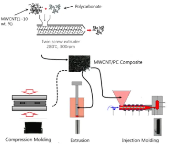
Fig. 1. Schematic diagram of the whole process including the preparation of the multi-walled carbon nanotube (MWCNT)/polycarbonate (PC) composite, compression molding, extrusion, and injection molding.
Sample preparation and characterizations: A schematic diagram for the whole process, including the preparation of the MWCNT/PC composite, compression molding, extrusion, and injection molding is shown in Fig. 1. PC/MWCNT nanocomposites were dried in an air circulating oven at 110 °C for 24 h.
Dried samples were then injection-molded into rectangular plates (152 mm x 152 mm x 3.2 mm) in a Gold-Star injection molding machine. Injection flow rate, injection melt temperature, and mold temperature were 123 cm3/s, 280 °C, and 80°C, respectively.
The melt extruding experiments were carried out in a melt flow indexer (C-505902, Toyoseiki Co. Ltd, Japan) to investigate the effects of shear rate on the electrical conductivity of PC/MWCNT nanocomposites.
The PC/MWCNT nanocomposite was filled into a sample reservoir and then the melt indexer was heated at 280°C for 5 minutes to obtain a molten state. The melt was extruded through a capillary die (diameter;
2.0 mm, length; 8 mm) with load varying from 1.2 Kgf to 6.7 Kgf.
The surface resistivities of the samples were measured by using a resistivity meter (SRM-110, Wolfgang warmbier, Ltd, Germany). Because the surface resistivity is very sensitive to temperature and humidity, all measurements were conducted at 23°C, 50% RH according to ASTM D257. Each sample was cleaned with ethanol prior to measurements.
3. Results and Discussions
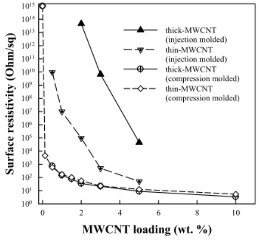
Fig. 2 shows the surface resistivity of the PC/MWCNT nanocomposite as a function of MWCNT weight fraction. Two different MWCNTs were used in this study. The average diameter of one MWCNT (referred as thick-MWCNT) is reported as ~ 20 nm while that of the other MWCNT (referred as thin-MWCNT) is about ~ 10 nm according to the manufacturers. The surface resistivity of compression molded pristine PC (~1015 Ohm/sq) is drastically decreased below 104 Ohm/sq by incorporation of only 0.125 wt. % of MWCNTs. For the compression molded samples, the two different MWCNTs do not provide a significant difference in the surface resistivity, and the percolation threshold is found to be below 0.125 wt.
%. This value is somewhat lower than reported values [1], likely due to the excellent mixing efficiency of the extruder used in the present study. On the other hand, it was observed that the surface resistivities (and thus the percolation threshold points) of the injection molded samples are much higher than those of the compression molded samples and the type of MWCNT
affects the surface resistivity of the injection molded nanocomposite to a great extent.
Through several works on the effects of high speed polymer processing (including injection molding and fiber spinning) on the orientation of MWCNTs and the electrical conductivity of the MWCNT/polymer nanocomposites, the relationships between them are now well understood [7-10]. The high speed polymer processing induces orientation of the MWCNTs. When the MWCNTs orient in the flow field, the number of tube-tube contacts decreases and the conductive MWCNT paths diminished. As a consequence, the conductivity of the polymer/MWCNT nanocomposites is decreased by high speed processing [7-10].
MWCNT loading (wt. %)
0 2 4 6 8 10
Surface resistivity (Ohm/sq)
100 101 102 103 104 105 106 107 108 109 1010 1011 1012 1013 1014 1015
thick-MWCNT (injection molded) thin-MWCNT (injection molded) thick-MWCNT (compression molded) thin-MWCNT (compression molded)
Fig. 2. Surface resistivity of PC/MWCNT nanocomposite as a function of MWCNT weight fraction.
Surface resistivity of the injection molded PC/MWCNT nanocomposite was influenced by the location of the sample. Data were measured at the middle of the injection molded sample.
It was observed that the nanocomposite containing the thin-MWCNTs shows much lower surface resistivity than its counterpart, as shown in Fig. 2. The difference in the surface resistivity is more than 7 decades at 3 wt. % of MWCNTs and 3 decades at 5 wt. %. This huge difference by the MWCNT type was not reported before and is believed to originate from the difference of the MWCNTs investigated. According to the MWCNT manufacturers, the average
length-to-diameter (aspect) ratio of the thin-MWCNTs is about 160 whereas the aspect ratio of the thick-MWCNT ranges from 50 to 1200. Statistical information about the distribution of the thick-MWCNT’s lengths is not provided for the thick-MWCNTs, but it is inferred that the thick-MWCNTs haves a higher average aspect ratio than the thin-MWCNTs (50 ~ 1200 over 160) due to the following reasons. TEM images shown in reference [11] (where identical MWCNTs were used with the thin-MWCNT) reveal that the length of thin-MWCNTs is significantly shorter than those of thick-MWCNT, as also shown in reference [12]. Furthermore, the length of the MWCNTs in MWCNT/polymer composites is known to be significantly reduced by high shear force after melt processing [11, 13-14]. Since the thin-MWCNTs are weaker (because it is thinner) than the thick-MWCNTs, the aspect ratio of the thin-MWCNTs becomes even lower than that of its counterpart after melt processing.
When the MWCNTs are subjected to an external flow field in polymer melts, they orient to the flow directions. According to the slender body theory [15], when the aspect ratio of the rigid body is greater than 5, the orientation is not sensitive to the aspect ratio.
The slender body theory assumes that the particles are rigid and not deformable. However, the MWCNTs can bend, be coiled, and be stretched by an external force, as shown in many studies [7-13]. Their shapes are regarded as somewhere between a rigid slender body and polymer molecule. Therefore, it is assumed that MWCNTs with lower aspect ratio orient to a lesser extent than MWCNTs with higher aspect ratio. This is analogous to the observation that higher molecule weigh polymers can orient more easily during processing than lower molecular weight polymers.
shear rate (1/s)
0 50 100 150 200
Surface resistivity (Ohm/sq)
102 103 104 105 106 107 108 109 1010 1011
2 wt.%
3 wt.%
5 wt.%
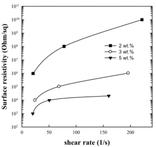
Fig. 3. Surface resistivity as a function of shear rate for PC/thick-MWNT nanocomposite extruded in a melt flow indexer. Numbers shown in the legend indicate the weight % of thick-MWCNTs incorporated in the nanocomposite.
Fig. 3 shows the surface resistivity of the PC/MWCNT nanocomposite extruded in a melt flow indexer as a function of shear rate. Flow rate (and thus shear rate) can be controlled by applying different weights, which press the molten polymer with different forces. It is seen that the conductivity (inverse of the resistivity) decreased with the shear rate. This is attributed to the flow induced orientation of the MWCNTs. Since higher shear rate increases the orientation of the MWCNTs, the number of tube-tube contacts decreases and the conductive paths are diminished, as explained previously. Therefore, it is inferred that the conductivity of the injection molded PC/MWCNT nanocomposite is also affected by the injection molding conditions. Reference [10] showed through experiments that higher injection speed and lower melting (and mold) temperature reduce the conductivity of the composite, because these conditions produce a higher shear rate during the filling stage of an injection molding process.
diameter of extradates (mm)
0.0 0.5 1.0 1.5 2.0
Surface resistivity (Ohm/sq)
102 103 104 105 106 107 108 109 1010 1011
2 wt.%
3 wt.%
4 wt.%
Fig. 4. Surface resistivity of the PC/thick-MWNT nanocomposite extruded in a twin screw extruder as a function of extrudate diameter.
Fig. 4 shows the surface resistivity of PC/thick-MWNT nanocomposites extruded in a twin screw extruder as a function of the extrudate diameter.
All composites were prepared at the same extrusion rate. Thus, the shear rate in the extrusion die is the same (approximately ~ 30 1/s), but the pulling speed of the pelletizer was varied, which produces various diameters of extrudates. Thinner extrudates were formed at a higher extensional rate and vice versa. It was found that the conductivity increased with the extensional rate. This is also attributed to the flow induced orientation of the MWCNTs. It appears that the variation of the conductivity by change of the extensional rate is greater than that by the shear rate.
For the nanocomposite with 3 wt. % thick-MWCNTs, the variation is about two decades by change of the shear rate, 25 to 200 1/s, in the shear flow (as shown in Fig. 3), whereas the variation is about 5 decades by change of the extrudate diameter, 2 mm to 0.2 mm, in the extensional flow. It has frequently been reported that the extensional flow is more dominant than the shear flow in orientation of the polymer chains and drop deformation of immiscible polymer blends. It is inferred that the orientation of the MWCNTs is also dominated by the extensional flow.
Fig. 5. SEM images of MWCNT powder at two magnifications. Left three photos: thick-MWCNT;
Right three photos: thin-MWCNT.
In Fig. 5, SEM images of the characteristic features of the two MWCNTs were shown. The SEM micrographs of as-received nanotube powders illustrate more loosely packed for thin-MWCNT, whereas thick-MWCNT shows denser. Furthermore, at higher magnification, the nanotubes of thin-MWCNT are more aligned. Therefore, it is proved that the thin-MWCNT is easily oriented by the external flow filed. All experimental observation shown earier is well understood by this characteristic features of the two MWCNTs.
In this study, we found that type of MWCNT affects the conductivity of the PC/MWCNT nanocomposite to a great extent. This finding has never been reported before. It is noteworthy that the difference in the conductivity between the nanocomposites from two different MWCNTs was very huge. Another factor other than flow induced orientation of the MWCNTs may contribute to the huge difference in conductivity.
It is possible that the flow induced migration of the MWCNTs from the surface of the injection molded part toward the center and also induced aggregation of the MWCNTs. This issue will be clarified in future work.
4. Conclusion
In this study, we investigated various factors affecting the conductivity of a multiwall carbon nanotube (MWCNT)/PC nanocomposites, including the type of MWCNT, shear rate, and extensional rate. It was found that MWCNTs having a higher aspect ratio provide lower electrical conductivity in injection molded PC/MWCNT nanocomposites while the conductivities of compression molded samples from two different MWCNTs are the same. The nanocomposite samples prepared under a higher extensional rate and shear rate showed lower electrical conductivity.
References
[1] W. Bauhofer, J. Z. Kovacs, “A Review and Analysis of Electrical Percolation in Carbon Nanotube Polymer Composites,” Comp. Sci. Tech. Vol. 69, No. 10, pp.
1486–1498, 2009.
[2] P. Po¨tschke, M. Abdel-Goada, I.A.S. Dudkinb, D.
Lellingerb, “Rheological and dielectrical characterization of melt mixed polycarbonate-multiwalled carbon nanotube composites,” Polymer, Vol. 45, No. 26, pp.
8863–8870, 2004.
[3] S. Subramoney, “Novel nanocarbons—structure, properties, and potential applications,” Adv. Mater., Vol.
10, No. 15, pp. 1157–1171, 1998.
[4] J. P. Salvetat, G. A. D. Briggs, J. M. Bonard, R.
R.Bacsa, A. J. Kulik, T. Stockli, N.A. Burnham, L.
Forro, “Elastic and shear moduli of single-walled carbon nanotube ropes,” Phys. Rev. Lett., Vol. 82, No. 5, pp.
944–947, 1999.
[5] S. Geetha, K. K. S. Kumar, C. R. K. Rao, M. Vijayan, D. C. Trivedi, "EMI shielding: Methods and materials - A review," J. Appl. Polym. Sci., Vol. 112, No. 4, pp.
2073–2086, 2009.
[6] M. Taya, “Electronic Composites: Modeling, Characterization, Processing, and MEMS Applications.
Cambridge University Press; Ch. 6 Percolation model pp. 173-191, 2005.
[7] S. Abbasi, P. J. Carreau, A. Derdouri, “Flow induced orientation of multiwalled carbon nanotubes in polycarbonate nanocomposites: Rheology, conductivity and mechanical properties,“ Polymer, Vol. 51, No. 4, pp.
922–935, 2010.
[8] S. B. Kharchenko, J. F. Douglas, J. Obrzut, E. A.
Grulke, K. B. Migler, “Flow-induced properties of nanotube-filled polymer materials,” Nature Materials, Vol. 3, pp. 564 –568, 2004.
[9] P. Po¨tschke, H. Bru¨nig, A. Janke, D. Fischer, D.
Jehnichen, “Orientation of multiwalled carbon nanotubes in composites with polycarbonate by melt spinning,”
Polymer, Vol. 46, No. 23, pp. 10355–10363, 2005.
[10] T. Villmow, S. Pegel, P. Po¨tschke, U. Wagenknecht,
“Influence of injection molding parameters on the electrical resistivity of polycarbonate filled with multi-walled carbon nanotubes,” Comp. Sci. Tech., Vol.
68, pp. 777–789, 2008.
[11] B. Krause, T. Villmow, R. Boldt, M. Mende, G. Petzold, P. Pötschke, “Influence of dry grinding in a ball mill on the length of multiwalled carbon nanotubes and their dispersion and percolation behaviour in melt mixed polycarbonate composites,” Comp. Sci. Tech., Vol. 71, No. 8, pp. 1145–1153, 2011.
[12] G. Lim, K. Min, G. Kim, “Effect of cooling rate on the surface resistivity of polymer/multi‐walled carbon nanotube nanocomposites.” Polym. Eng. Sci., Vol. 50, No. 2, pp. 290–294, 2010.
[13] B. Krause. R. Boldt. P. Pötschke. “A method for determination of length distributions of multiwalled carbon nanotubes before and after melt processing,”
Carbon, Vol. 49, No. 4, pp. 1243-1247, 2011.
[14] B. Krause, M. Mende, P. Pötschke, G. Petzold.
“Dispersability and particle size distribution of CNTs in an aqueous surfactant dispersion as a function of ultrasonic treatment time,” Carbon, Vol. 48, No. 10, pp.
2746-2754, 2010.
[15] L. Jianzhong, Z. Weifeng, Y. Zhaosheng, “Numerical research on the orientation distribution of fibers immersed in laminar and turbulent pipe flows,” J.
Aerosol Science, Vol. 35, No. 1, pp. 63–82, 2004.
손 영 곤(Younggon Son) [정회원]
•1988년 2월 : 서울대학교 화학공학 과 (공학사)
•1990년 2월 : 한국과학기술원 화학 공학과 (공학석사)
•1998년 2월 : 서울대학교 화학공학 과(공학박사)
•2002년 9월 ~ 현재 : 공주대학교 신소재공학부 교수
<관심분야>
고분자가공, 고분자 블렌드
부이 둑낫(Duc Nhat Bui) [정회원]
•2017년 3월 : 베트남 호치민 대학 화학공학과 졸업
•2017년 3월 ~ 2018년 2월 : ㈜ 효 성 호치민 공장 근무
•2018년 3월 ~ 현재 : 공주대학교 신소재 공학부 석사과정
<관심분야>
고분자 복합재료