Journal of Internet Computing and Services(JICS) 2018. Apr.: 19(2): 9-15 9
Energy Efficient Adaptive Relay Station ON/OFF Scheme for Cellular Relay Networks
김 세 진1*
Se-Jin Kim ABSTRACT
This paper proposes an energy efficient adaptive relay station ON/OFF scheme with different frequency reuse factors (FRFs) to enhance the system throughput and reduce the transmission energy consumption for the transparent mode of 2-hop cellular relay networks (CRNs) based on orthogonal frequency division multiple access and time division duplex. In the proposed scheme, the base station turns on or off the relay stations (RSs) when they are overutilized and undertuilized based on the traffic density of the cell coverage, respectively. Through the simulation results, we show that the proposed scheme outperforms the conventional CRN in terms of the energy consumption with the same system throughput. Further, in order to increase the system throughput with low energy consumption, the best way is FRF 1 when the number of operating RSs is up to 4 and FRF 2 otherwise.
☞ keyword : Cellular relay network, OFDMA, Adaptive, Relay station, Energy saving
1. Introduction
Recently, cellular relay networks (CRNs) have been proposed as an attractive solution for the next generation mobile communication, i.e., LTE-A and 5G, [1-3] since they can enhance the system performance. However, the energy consumption of the CRN increases by adding relay stations (RSs) and the RSs waste their energy when the traffic density is low. Thus, an adaptive power control scheme is necessary to reduce the energy consumption of the RSs.
In [4], authors proposed a path selection algorithm for two-hop CRNs to enhance the downlink (DL) throughput and energy consumption. The proposed scheme determines either a single-hop or two-hop path with six RSs using different frequency reuse factors but the RSs always operates, i.e., the RSs are not turned off. In [5], an optimal energy saving scheme has been presented for the conventional cellular network. It allows some cells to be switched off and other cells to remain active, and this extends the service coverage during low traffic periods. The energy consumption models are analyzed by simply using the traffic load in a base station
1Department of Computer Science and Statistics, Chosun University, Gwangju 61452, Korea.
* Corresponding author ([email protected])
[Received 24 July 2017, Reviewed 25 July 2017(R2 16 November 2017), Accepted 10 January 2018]
(BS) coverage over a day and showed superior performance in terms of the energy consumption. In [6], authors proposed an energy efficient RS operation scheme to reduce the energy consumption of the transmission power for the DL of the non-transparent mode of 2-hop CRNs when the system is underutilized such as during night periods. That is, some BSs change their service modes into the single-hop mode using the same transmission power of RSs to reduce the energy consumption while others simultaneously change their service modes into the 3-hop mode using the new RSs from neighbor cells for their second tier RSs.
This paper proposes an energy efficient adaptive relay station ON/OFF scheme with different frequency reuse factors (FRFs) to enhance the system throughput and reduce the transmission energy consumption for the transparent mode of 2-hop CRNs based on orthogonal frequency division multiple access and time division duplex (OFDMA-TDD). In the proposed scheme, the BS turns on or off the RSs when they are overutilized and undertuilized based on the traffic density of the cell coverage, respectively. Through the simulation results, we show that the proposed scheme outperforms the conventional CRN in terms of the energy consumption with the same system throughput. Further, in order to increase the system throughput with low energy consumption, the best way is FRF 1 when the number of operating RSs is up to 4 and FRF 2 otherwise.
ISSN 1598-0170 (Print) / ISSN 2287-1136 (Online) http://www.jics.or.kr
Copyright ⓒ 2018 KSII
FRF Frequency reuse patterns 1
2 3 6
G1(RS 1, 2, 3, 4, 5, 6) G1(RS 1, 3, 5), G2(RS 2, 4, 6) G1(RS 1, 4), G2(RS 2, 5), G3(RS 3, 6) Each RS uses different subchannel groups (G1~G6)
(Table 1) Frequency reuse patterns for 6 RSs in RZ
(Figure 1) System models for 2-hop CRNs
The remainder of this paper is organized as follows.
Section 2 introduces various system models while Section 3 proposes an energy efficient adaptive RS ON/OFF scheme.
Section 4 evaluates the performance results and finally section 5 concludes this paper with future research direction.
2. System Model
2.1 System Topology and Frame Structure Fig. 1 describes system models for the transparent mode of 2-hop CRNs. Fig. 1-(a) shows the system topology that consists of hexagonal cells of radius R and the cell coverage (C) which is obtained via ∙. A BS is located at the center of each cell and surrounded by 6 fixed RSs that are placed at a distance of DRS from the BS. Then, the given total area is covered by a target cell and 19 cells in two-tiers, i.e., 6 and 12 cells are placed in the first and second tiers, respectively and the center cell is observed. Fig.
1-(b) shows an OFDMA-TDD frame structure for the
transparent mode. The BS divides the timeline into contiguous frames each of which includes the DL and uplink (UL) subframes. Then, the DL and UL subframes are further divided into two zones, i.e., access zone (AZ) and relay zone (RZ). For example, during the DL subframe, the BS transmits data to both mobile stations (MSs) and RSs in AZ, i.e., BS-RS/MS communication, and then the RSs subsequently relay the received data to their serving MSs but the BS is in silent mode in RZ, i.e., RS-MS communication.
Further, the technique of frequency reuse is considered to improve the overall network capacity and spectral efficiency.
We assume that the FRF is always 1 for AZ because the BS only transmits data to RSs and MSs within the BS region, whereas the RSs use different FRFs for RZ. Table 1 shows the frequency reuse patterns for 6 RSs in RZ. For instance, all RSs are in group 1, G1, for FRF 1 and they use the same subchannels while each RS is in different RS groups from G1
to G6 for FRF 6 and they use different subchannels. The number of subchannels for each group is obtained by (the number of total subchannels / the number of RS groups).
2.2 Channel Models
We use two wireless links, i.e., BS to RSs and BS/RS to MSs, for CRNs. For the wireless link between the BS and RSs, the line-of-sight can be practically realized by placing RSs at carefully selected locations such as on the roof of buildings. Thus, we use the IEEE 802.16 type D model that is used for the free-space path loss condition as below [7].
′
∆ ∆
′
where, d is the distance between the transmitter and receiver and d0= 100m. A = 20 ‧ log10(4d’0/) and is the wavelength
in meter. d’0 = d0‧10-((∆PLf+∆PLht)/10‧) and = a - b‧
hb+ c/hb where hb is the height of the receiving RS and MS antennas. ∆PLf is the correction factor for carrier frequency and ∆PLht is the height of the receiving antenna. ∆PLf and
∆PLht can be expressed as (2) and (3), respectively.
∆
∆
where, f is the carrier frequency in MHz and ht is the height of the transmitting BS (and RS) antennas. Further, a = 3.6, b = 0.005, and c = 20.
For the wireless link between the BS/RSs and MSs, we use the IEEE 802.16 type B model that is used for the intermediate path-loss condition as below [8].
∆ ∆ where, the parameters are the same height as type D path loss model but ∆PLht = -10.8‧log10(h/2). Further, a = 0.0075, b = 0.0065, and c = 0.005.
2.3 SINR Models for CRNs
We revise an SINR model in [6] to use for the performance evaluation of CRNs. In the SINR model, the interference mainly comes from two sources: intra-cell interference () and inter-cell interference ().
is caused by BS and/or RSs using the same channel within a cell while is caused by signals from BSs and/or RSs from other cells. We assume that L BSs are placed in a given area and each BS is surrounded by M RSs.
Then, the SINR of the MS or RS serviced by the BS can be expressed as (5).
where,
is the received signal power from a BS in the i-th cell (1≤i≤L) and PN is the white noise power. BSs are
in silent mode in RZ but and in AZ can be written as (6).
≠
On the other hand, the SINR of the MSs served by a RS from the j-th surrounding RSs (1≤j≤M) in the i-th cell can be expressed as (7).
The RSs are in the receive-mode in AZ but and
in RZ can be written as (8).
≠
≠
2.4 Resource Allocation and System Throughput To determine the path and analyze the system throughput of the i-th cell (Ti) which is in bps, we introduce a method for calculating the required number of symbols per second for the i-th cell () under the given traffic density () in Mbps/km2. The number of symbols for AZ () can be obtained by (9).
where, and are the numbers of symbols for the BS and all RSs and they can be written as (10).
∙
∙
where, N is the modulation and coding scheme (MCS) levels.
and
are the areas of the n-th MCS level for the BS and the m-th RS in the i-th cell, respectively. and are the transmission rates (modulation efficiency)
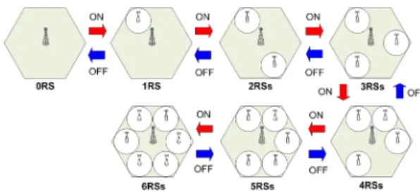
(Figure 2) An example of the proposed adaptive RS ON/OFF scheme to operate RSs between 0 and 6
per symbol of the n-th MCS level for BS-MS and BS-RS communications in AZ, respectively.
The numbers of symbols for the RSs () in RZ is obtained by (11).
∙
where, and is the value of FRFs.
Therefore, can be represented as (12).
≤
where is the number of total symbols available for the DL of the BS and RSs and is assigned by the number of symbols per subcarrier per frame per second.
Consequently, maximum Ti can be written as (13).
∙
where, is maximum according to (12)
3. Proposed Energy Efficient Adaptive RS ON/OFF Scheme
Fig. 2 describes an example of the proposed adaptive RS ON/OFF scheme to operate RSs between 0 and 6 RSs. In the proposed scheme, the BS periodically receives information, e.g., traffic density, from the operating RSs and decides the RSs to turn on or off. For example, the BS turns on the RS when the BS and operating RSs are overutilized, i.e., they can not serve the amount of total data traffic in the cell coverage (Tcell) witch is obtained by while the BS turns off the RS when the BS and operating RSs are underutilized, i.e., they can serve Tcell after the BS reduces 1 RS from the number of currently operating RSs.
Fig. 3 describes the proposed adaptive RS ON/OFF scheme to turn on the RSs. Fig. 3-(a) shows the procedure of the proposed scheme to turn on the RSs. First, the BS periodically observes Ti and Tcell and decides to turn on the RSs when Tcell increases over Ti. Then, the BS exchanges messages, i.e., RS_WAKEUP_REQ and RS_WAKEUP_RSP,
with the RSs that are in sleep mode and the RSs wake up to listen to the MSs’ uplink signals for a while. After a few moments, the RSs send the MSs’ information, e.g., the link quality between the RSs and MSs and the amount of data traffic in the RS coverage, to the BS. Finally, the BS decides the target RS to turn on the power and then exchanges messages, i.e., RS_ON_REQ and RS_ON_RSP, with the targe RS. Finally, after the target RS turns on the power, it relays the data traffic between the BS and MSs while other RSs go into the sleep mode again. Fig. 3-(b) shows the logic flow for the BS decision to turn on the RSs according to Ti
and Tcell. First, the BS calculates Ti and decides to turn on the RS if Ti < Tcell. Then, the BS turns on the RS one by one until all RSs are turned on, i.e., j and M are the same.
Fig. 4 describes the proposed adaptive RS ON/OFF scheme to turn off the RSs. Fig. 4-(a) shows the procedure of the proposed scheme to turn off the RSs. First, the BS periodically observes Ti and Tcell and decides an operating RS as a target RS to turn off when Tcell decreases to lower than Ti. Then, the BS exchanges messages, i.e., RS_OFF_REQ and RS_OFF_RSP, with the targe RS to trun off. Finally, the BS communicates with the MSs served by the target RS after the target RS turns off their power and goes into the sleep mode. Fig. 4-(b) shows the logic flow of the BS decision to turn off the RS according to Ti and Tcell. That is, the BS calculates Ti and decides to turn off the RS if . Here, Ti is obtained by the BS with j-1 RSs when the number of operating RSs is j. Then, the BS turns off the RS one by one until all RSs are turned off, i.e., j < 0.
(Figure 3) Proposed energy efficient adaptive RS ON/OFF scheme to turn on the RSs
(Figure 4) Proposed energy efficient adaptive RS ON/OFF scheme to turn off the RSs
4. Performance Evaluation
We evaluate the DL performance of the proposed adaptive RS ON/OFF scheme and compare it to that of the conventional CRN (CCRN) which always turns on the power of all RSs in terms of the system throughput and energy consumption using a Monte Carlo simulation. The transmit
powers of the BS and RS are 20W and 5W, respectively.
The energy consumption of one RS is 10% of that of the BS.
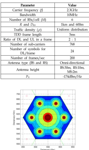
As shown in Table 1, we evaluate the system performance with different values of FRFs. Log-normal shadow fading is only considered for the access links with zero mean and a standard deviation of 8.0 dB. Table 2 describes the key system parameters while the MCS option with a bit error rate
Parameter Value Carrier frequency (f) 2.3GHz
Bandwidth 10MHz
Number of RSs/cell (M) 6 R and DRS 1km and 600m Traffic density () Uniform distribution
TDD frame length 5ms
Ratio of DL and UL in a frame 2 : 1 Number of sub-carriers 768 Number of symbols for
DL/frame 24
Number of frames/sec 200 Antenna type (BS and RS) Omni-directional
Antenna height BS:30m, RS:10m, MS:2m
PN -174dBm/Hz
(Table 2) System parameters
(Figure 5) An example of the SINR distribution of the cell coverage with 6 RSs in the CRN
0 1 2 3 4 5 6
2 2.5 3 3.5 4
The number of operating RSs
Throughput (Mbps/cell)
FRF 1 FRF 2 FRF 3 FRF 6
(Figure 6) System throughput with different FRFs
0.6 0.7 0.8 0.9 1 1.1 1.2 1.3 1.4 1.5 1.6
0.6 0.65 0.7 0.75 0.8 0.85 0.9 0.95 1
Traffic density (Mbps/km2)
Total energy consumption(%)
Fixed FRF 2 FRF 1 FRF 2 FRF 3 FRF 6
(Figure 7) Total transmission energy consumption
less than 10-6 is in [6] and the unit of modulation efficiency is bit/symbol/subcarrier [8]. Fig. 5 presents an example of the SINR distribution of the coverage of the center cell with 6 RSs in the CRN.
Fig. 6 shows the system throughput with different FRFs when the number of operating RSs is from 0 to 6 RSs. FRF 1 achieves the highest Ti from 2 to 3 RSs because the RSs have a small amount of interference with each other but the interference from the RSs is highly increased over 4 RSs and thus Ti of FRF 1 is less than that of FRF 2. Further, FRF 6 always achieves the lowest throughput because the RSs use different subchannel groups even though every RS has no interference from neighbor RSs. The results with 6 RSs are
the same as the performance of the CCRN since the CCRN always operates all RSs. Therefore, in the CCRN, FRF 2 and 6 have the highest and lowest throughputs, respectively.
Fig. 7 shows the total transmission energy consumption of the proposed scheme compared to the CCRN based on . As shown in Fig. 6, the CCRN has the highest throughput using 6 RSs with FRF 2, i.e., fixed FRF 2, and the energy consumption is always 1. On the other hand, in the proposed scheme, all FRFs have the same energy consumption when
< 0.95 Mbps/km2. However, FRF 1 and 3 have the lowest energy consumptions when is lower than 1.2 and 1.48 Mbps/km2, respectively. Therefore, it is shown that the proposed scheme can reduce from 37% to 6% compared to the CCRN with FRF 2 when is from 0.83 to 1.48 Mbps/km2, respectively.
◐ 저 자 소 개 ◑
김 세 진(Se-Jin Kim) 2004년 조선대학교 전산학과(이학사) 2006년 고려대학교 대학원 전산학과(이학석사) 2010년 고려대학교 대학원 전산학과(이학박사) 2015년~현재 조선대학교 컴퓨터통계학과 교수
관심분야 : 정보통신, 이동통신, 사물인터넷, Software Defined Network etc.
E-mail : [email protected]
5. Conclusion
In this paper, we proposed an energy efficient adaptive RS ON/OFF scheme for the transparent mode of 2-hop CRNs based on OFDMA-TDD to reduce the DL energy consumption. In the proposed scheme, the BS turns on or off the RSs when the BS and operating RSs are overutilized or undertuilized based on , respectively. Through the simulation results, it is shown that the proposed scheme outperforms the CCRN in terms of the energy consumption with the same system throughput. Further, in order to increase the system throughput with low energy consumption, the best way is FRF 1 when the number of operating RSs is up to 4 and FRF 2 otherwise. For the future work, we are planning to study a dynamic subchannel assignment with the proposed RS ON/OFF scheme to evaluate the system throughput, energy consumption, delay and fairness.
Reference
[1] N. Mastronarde, V. Patel, J. Xu, L. Liu, and M. V.
D. Schaar, “To Relay or Not to Relay: Learning Device-to-Device Relaying Strategies in Cellular Networks,” IEEE Transactions on Mobile Computing, Vol. 15, No. 6, pp.1569-1585, 2016.
https://doi.org/10.1109/TMC.2015.2465379
[2] W. Guo, T. O'Farrell, "Relay Deployment in Cellular Networks: Planning and Optimization,"IEEE Journal on Selected Areas in Communications, Vol.31, No.8,
pp.1597-1606, 2013.
https://doi.org/10.1109/JSAC.2013.130821
[3] IEEE Std 802.16j-2009, “IEEE Standard for Local and metropolitan area networks Part 16: Air Interface for Broadband Wireless Access Systems Amendment 1: Multihop Relay Specification,” 2009 https://doi.org/10.1109/IEEESTD.2009.5167148 [4] S.-H. Kim, S.-J. Kim, J.-Y. Lee, B.-C. Kim, "Energy
efficient path selection scheme for OFDMA-based two-hop cellular systems," Journal of Systems Architecture, Vol.59, No.10, pp.947-952, 2013.
https://doi.org/10.1016/j.sysarc.2013.06.005
[5] M. Ajmone Marsan, L. Chiaraviglio, D. Ciullo, M.
Meo, “Optimal Energy Savings in Cellular Access Networks,” GreenComm 2009, Dresden, Germany, 2009. https://doi.org/10.1109/ICCW.2009.5208045 [6] S.-J. Kim, B.-B. Lee, Y.-C. Ko, S. Ryu, H.-W. Lee,
and C.-H. Cho, “An Adaptive Power Saving Scheme in OFDMA-TDD based Cellular Relay Networks,”
IEICE Trans. Communications Letters, Vol.E93-B, No.06, pp.1657-1660, 2010.
http://doi.org/10.1587/transcom.E93.B.1657
[7] IEEE 802.16j-06/013r3, Multi-hop Relay System Evaluation Methodology (Channel Model and Performance Metric), 2007.
http://ieee802.org/16/relay/docs/80216j-06_013r3.pdf [8] D. Yoon, K. Cho, J. Lee, “Bit Error Probability of
M-ary Quadrature Amplitude Modulation,” IEEE VTC-Fall, Vol.5, pp.2422-27, Sept. 2000.
https://doi.org/10.1109/VETECF.2000.883298