FBG Sensor Probes with Silver Epoxy for Tracing the Maximum Strain of Structures
Jooeun Im*, Mihyun Kim*, Ki-Sun Choi**, Tae-Kyung Hwang*** and Il-Bum Kwon*✝
Abstract Structures can be evaluated their health status by allowable loading criteria. These criteria can be determined by the maximum strain. Therefore, in order to detect this maximum strain of structures, fiber optic Bragg grating(FBG) sensor probes are newly designed and fabricated to perform the memorizing detection even if the sensor system is on-and-off. The probe is constructed with an FBG optical fiber embedded in silver epoxy.
When the load is applied and removed on the structure, the residual strain remains in the silver epoxy to memorize the maximum strain effect. In this study, a commercial Al-foil bonded FBG sensor probe was tested to investigate the detection feasibility at first. FBG sensor probes with silver epoxy were fabricated as three different sizes. The detection feasibility of maximum strain was studied by doing the tensile tests of CFRP specimens bonded with these FBG sensor probes. It was investigated the sensitivity coefficient defined as the maximum strain divided by the residual strain. The highest sensitivity was 0.078 of the thin probe having the thickness of 2 mm.
Keywords: Sensor Probe, FBG Sensor, Composite, Residual Strain
[Received: September 10, 2013, Revised: October 22, 2013, Accepted: October 23, 2013] *Korea Research Institute of Standards and Science, Daejeon 305-340, Korea, **FINISA Korea Co. Ltd., Gwangju 500-460, Korea, ***Agency for Defence Development, Daejeon 305-152, Korea, ✝Corresponding Author: [email protected]
ⓒ 2013, Korean Society for Nondestructive Testing
1. Introduction
Structures can be evaluated their health status with allowable loading criteria. These criteria can be determined by the maximum strain. Therefore, in order to detect this maximum strain of structures, FBG sensor probes are newly designed and fabricated to perform the detection without any measurement uncertainty even if the sensor system is on-and-off. The maximum strain of structural materials can be traced by measuring the residual strain in the probe. FBG sensors have been developed for applying the field of structural health monitoring, such as, strain measurements, failure diagnostics, thermal measurements, pressure monitoring. FBGs have many advantages, for example, electro-magnetic resistance, small size, resistance to corrosion, multiplexing of sensors along a single fiber.
Moreover, FBGs can be used for the measure-
ment of parameters manifesting as the changes of strain or temperature [1-4].
Carbon fiber reinforced plastics (CFRP) are used for almost modern commercial aircrafts as a primary structural component. For structural health monitoring, the surface mounted or embedded FBG sensors have been replaced strain gauges [7]. In order to monitor the health status of composite materials, the maximum strain detection is very important because we can determine the structural safety criteria from this information. However, CFRP is fully recovered their strain after removing the loading.
Therefore, the maximum strain of CFRP is not easy to detect without continuous measurement.
However, if an FBG probe is coated or bonded
with some plastic materials, this probe will have
some amount of the residual strain after
experiencing maximum strain. Therefore, if we
know the relation between residual strain and
maximum strain, the maximum strain can be
glass optical fibers from moisture attack, metallic coatings are applied on optical fibers, such as, aluminum, indium, tin, antimony, zinc, lead, copper, nickel, and gold [5]. Some of these fibers exhibit higher resistance to moisture attack and significantly higher strength than polymer- coated fibers, and some of these fibers can withstand relatively higher temperature.
On the one hand, optical fibers are coated to improve mechanical properties, such as, Young’s modulus, thermal expansion coefficient and Poisson’s ratio, enhance reliability and protect against harsh environment applications [6].
Although these coating techniques of optical fibers have been improved the properties of optical fibers, there were no studies on the maximum strain detection of structures using the residual strain of coating materials.
Therefore, we designed and fabricated new FBG sensor probes embedded in silver epoxy molding that can trace the maximum strain of structural materials by the residual strain. The feasibility was studied using Al-foil bonded FBG probes. The detection sensitivity was investigated by doing tensile tests of CFRP specimens with the FBG probes with silver epoxy.
2. Detection Principle of an FBG Probe with Silver Epoxy
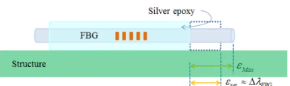
A new sensing probe based on the principle of FBG sensors is proposed for detecting the maximum tensile strain of structures. This probe is designed with an FBG fiber embedded in silver epoxy shown in Fig. 1. This figure also shows how the probe is operated when the maximum strain is induced on the structure.
Fig. 1 Schematics of an FBG probe with silver epoxy
This probe should be attached on the surface of the structure to detect the maximum strain also shown in Fig. 1. When the load is applied on the host structural material, the silver epoxy and the FBG fiber are extended to the maximum strain, ε
MAX. Also, when the load is removed, then the silver epoxy with an FBG fiber will have some residual strain, ε
res, according to the force equilibrium between the host structural material and the silver epoxy. Therefore, this residual strain can be detected by the FBG fiber in the silver epoxy shown in Fig. 1. In order to use this sensing technique, the sensitivity coefficient, the ratio between the relation between the residual and maximum strain, is defined as:
(1)
Where ε
MAXis the maximum strain, ε
resis the residual strain of the sensor probe. If the residual strain is proportionally remained with the maximum strain in the probe, then the max- imum strain can be determined by using Eq. 1.
The physical dimension of the probe can influence the sensitivity coefficient because the residual strain is determined by the force equilibrium between the probe and the host structural material.
3. Feasibility Study Using an Al-Foil Bonded FBG Probe
The probe should be able to sense the
residual strain in order to detect the structural
maximum strain. Therefore, the sensitivity
Fig. 2 An aluminum bonded FBG probe
Fig. 3 Schematic diagram of an Al-foil bonded FBG sensor probe on a CFRP specimen.
Fig. 4 A CFRP specimen with an Al-foil bonded FBG sensor in universal testing machine
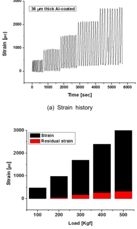
(a) Strain history
(b) Maximum and residual strain
Fig. 5 Strain history and maximum/residual strain of the Al-foil bonded FBG probe
coefficient should be studied for the probe with plastic materials. An Al-foil bonded FBG sensor probe is designed as one film shape of an FBG inserting between two Al-foils, the thickness of each foil is 36 μm, shown in Fig. 2. There is an FBG sensor probe, which is fully bonded on the surface of structures shown in the upper part of Fig. 2. Also, the probe is fabricated with commercially available aluminum foil of the thickness, 18 µm, bonded on an FBG using instant adhesive (CC-33A, cyano-acrylate base, Kyowa). To study the feasibility of these probes, CFRP specimen, [0
16]
T, was prepared as 2 mm thickness, 25 mm width and 150 mm length shown in Fig. 3. Al-foil bonded FBG sensor probe was bonded on the upper surface, and the 5 mm length of electric strain gauge was also bonded on the bottom surface of the specimen.
Fig. 4 shows the specimen with a fully bonded
FBG sensor. Universal testing machine (UTM)
was used to induce the strain on the specimens,
this machine was controlled as the condition of
constant displacement speed, 1 mm/min, and the
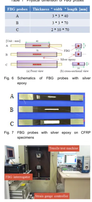
Fig. 6 Schematics of FBG probes with silver epoxy
Fig. 7 FBG probes with silver epoxy on CFRP specimens
Fig. 8 Experimental setup for tensile test
controlled computer, an FBG interrogator and specimen. The FBG sensor data is acquired by the FBG interrogator (CyTroniq) and the electric strain gauge data is also gathered through an A/D converter from the strain gage conditioner.
The maximum and residual strains are acquired from this Al-bonded FBG probe and shown in Fig. 5. The strain was remained at second loading step. It means that the residual strain can be generated at lower strain of 1000 micro-strain. When the maximum strain is increased, the residual strain is also increased.
The sensitivity coefficient between the maximum and residual strain is calculated as 0.15.
4. Detection Sensitivity of FBG Probes Embedded in Silver Epoxy
The FBG probe with silver epoxy is designed referring from the reference [8] as shown in Table 1. These probes are designed to investigate the effect of FBG location and the width of the probes on the sensitivity coefficient as shown in Fig. 6.
Silver epoxy is prepared to be fabricated with an FBG optical fiber because this silver epoxy of about 10 GPa elastic modulus, can be plastically deformed when the host material of about 72 GPa elastic modulus experiences the maximum strain. This silver epoxy is a popu- larly commercialized product as a conductive and thermal polymer and it can be cured in room-temperature. The probes are fabricated as the following procedural steps. At first, silver epoxy is poured into a silicon mold. Secondly, an FBG fiber is positioned at the center or the bottom of the mold to the thickness direction.
At third step, These are cured in the oven at
100°C during almost 1 hour for fast hardening.
These probes are finally attached on the surfaces of each CFRP specimen for tensile test.
The fabricated FBG probes are attached on the surfaces of CFRP specimens shown in Fig.
7. The thickness, width and length of probe A
is 3 mm, 3 mm, 40 mm and the FBG position
is at the center of the probe. The size of probe
0 300 600 900 1200 1500 0
2000 4000 6000
Wavelength shift[pm]
Time[sec]
4 cm - length Ag epoxy
0 1000 2000 3000
0 2000 4000 6000 8000
Wavelength shift [pm]
Time [sec]
7 cm - Ag_center
0 1000 2000 3000
0 2000 4000 6000 8000
wavelength shift [pm]
Time [sec]
7 cm - Ag_wide
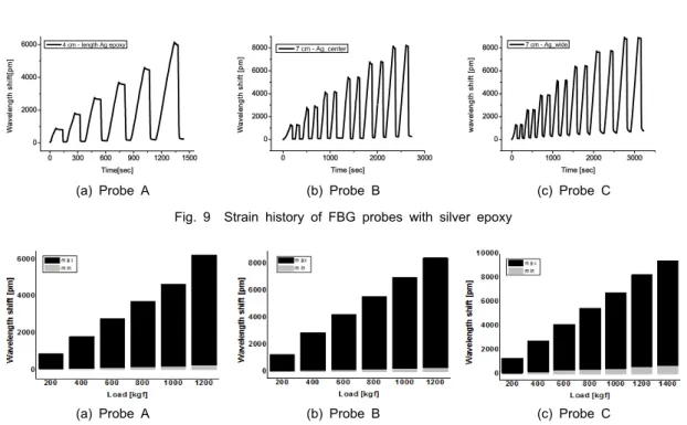
(a) Probe A (b) Probe B (c) Probe C
Fig. 9 Strain history of FBG probes with silver epoxy
(a) Probe A (b) Probe B (c) Probe C
Fig. 10 Residual strain change of each load step