Transverse Wave Propagation in [ab0] Direction of Silicon Single Crystal
Sangjin Yun*,**, Hye-Jeong Kim*,***, Seho Kwon*,*** and Young H. Kim*✝
Abstract The speed and oscillation directions of elastic waves propagating in the [ab0] direction of a silicon single crystal were obtained by solving Christoffel’s equation. It was found that the quasi waves propagate in the off-principal axis, and hence, the directions of the phase and group velocities are not the same. The maximum deviation of the two directions was 7.2°. Two modes of the pure transverse waves propagate in the [110] direction with different speeds, and hence, two peaks were observed in the pulse echo signal. The amplitude ratio of the two peaks was dependent on the initial oscillating direction of the incident wave. The pure and quasi-transverse waves propagate in the [210] direction, and the oscillation directions of these waves are perpendicular to each other. The skewing angle of the quasi wave was calculated as 7.14°, and it was measured as 9.76°. The amplitude decomposition in the [210] direction was similar to that in the [110] direction, since the oscillation directions of these waves are perpendicular to each other. These results offer useful information in measuring the crystal orientation of the silicon single crystal.
Keywords: Silicon Single Crystal, Transverse Wave, Polarization, Skewing
[Received: June 2, 2015, Revised: August 30, 2015 / October 7, 2015, Accepted: October 12, 2015] *Applied Acoustics Lab, Korea Science Academy of KAIST, Busan 47162, Korea, **Korea Advanced Institute of Science and Technology, Daejeon 34141, Korea, ***Seoul National University, Seoul 08826, Korea ✝Corresponding Author:
ⓒ 2015, Korean Society for Nondestructive Testing
1. Introduction
The propagation speed and the oscillating direction of the wave propagating through a solid can be calculated by Christoffel’s equation.
The propagating direction and the oscillating direction are parallel for the longitudinal wave and perpendicular for the transverse wave in isotropic medium. Wave velocity in anisotropic solids depends on propagation direction as well as on the direction of particle displacement.
Three modes of waves, one (quasi-) longitudinal and two (quasi-) transverse modes, can propagate in a bulk anisotropic medium. The quasi wave whose propagating direction and oscillating direction are neither parallel nor perpendicular can propagate in anisotropic medium. The direction of group velocity differs from that of phase velocity, and this phenomenon is called beam skewing [1].
The acoustical birefringence is a decomposi- tion of bulk transverse wave into two or more waves in the solid medium. Most of previous researches focused on the relationship between the acoustical birefringence and directions of the stress in the solid medium.
Properties of the acoustical birefringence observed in distorted solid and its similarity to optical birefringence shown in photoelastic materials was discussed [2]. Also, methods to analyze characteristics of solid materials based on ultrasonic birefringence have been proposed [3-7].
Quasi waves are categorized into quasi transverse wave and quasi longitudinal wave by their skewing angle. Quasi longitudinal wave has skewing angle closer to 0° and quasi transverse wave has skewing angle closer to 90°. Waves propagating in the direction between [210] and [310] has maximum skewing angle of 7.3°.
surface is one of the great concerns in non- destructive testing of highly anisotropic materials such as fiber-reinforced composites and austenitic steels. In order to assess these problems, numerical modeling such as modular multi- Gaussian beam(MMGB) was applied to study the effect of material anisotropy on ultrasonic beam profile [8,9].
In the present work, wave speeds and oscillating directions in [ab0] direction of silicon single crystal were obtained by solving Christoffel’s equation, and these propagation properties for [110] direction and [210] direction were confirmed by experiments. Especially, decompositions of transverse waves were mainly considered.
2. Christoffel’s Equation
Christoffel’s equation is expressed as below [10].
= 0 (1) Where is the density of a medium, is elasticity constant tensor, is wave number, is angular frequency, is particle displacement, and is unit tensor.
The following matrix equation should be satisfied if the equation (1) has a nontrivial solution.
= 0
= 0
Silicon crystal has cubic crystal structure and values of are given simply as following [11].
165.64 GPa
63.94 GPa
79.51 GPa
= 2.329 × 10³ kg/m3
3. Theoretical Analysis of Transverse Waves Propagation in [ab0] Direction of Silicon Crystal
[ab0] direction transverse waves propagate on xy-plane. Propagation directions of these waves are denoted by [cos sin ], where is the angle between the propagation direction and the x-axis. Speeds and oscillating directions of waves propagating in the silicon crystal were determined by putting [cos sin ] as the propagation direction vector in Christoffel’s equation.
Depending on the propagation direction of the wave, Christoffel’s equation gives two transverse waves and one longitudinal wave as a solution. For some propagating direction, the
Fig. 1 Speeds of transverse waves on xy-plane
Fig. 2 Speed of longitudinal wave on xy-plane
Fig. 3 Skewing angle in [ab0] direction
Table 1 Solution of Christoffel’s equation for incident wave on xy-plane
Wave Oscillating
direction Speed
Transverse [001] 5842.9 m/s
(Quasi-) transverse [ α0] Dependent (Quasi-) longitudinal [α0] Dependent
solution of Christoffel’s equation included waves whose propagation direction and the oscillating direction are neither perfectly parallel nor perfectly perpendicular. These waves are called either quasi-transverse wave or quasi-longitudinal wave, depending on the angle between the propagating direction and the oscillating direction.
In this case, the directions of phase and group velocities are not parallel and beam skewing appears. The solutions of Christoffel’s equation are shown in Figs. 1, 2 and 3. Fig. 1 and Fig.
2 show speeds of transverse waves and longitu- dinal wave in [ab0] direction, respectively. Fig.
3 shows the skewing angle, angle between phase and group velocities, of quasi waves in [ab0]
direction. Skewing angle of quasi-transverse
wave and that of quasi-longitudinal wave are equal. Waves propagating in [ab0] direction are summarized in Table 1.
When elastic wave propagates in principal axes such as [100]. [110] and [010], only pure waves exist. When is 19~20º or 70~71º from x-axis, skewing angle becomes maximum which is about 7.2º. Waves propagating in [110] direc- tion and [210] direction, which make skewing angle of 7.13º, were main concern of present work.
4. Ultrasound Propagation in [110] Direction 4.1. Birefringence in [110] Direction
Silicon plates of [110] direction orientation were employed for the study of propagation in [110] direction. Detailed specifications and coordinates of plates [12] are as follows:
Transverse [] 5842.9 m/s Transverse [] 4672.6 m/s Longitudinal [] 9133.8 m/s
Transducer of 20 MHz (Panametrics V220BA- RM, 6 mm element size with delay line of 13 mm diameter) that has 7 μs delay line produced the transverse wave. Shear wave couplant (Panametrics SWC) was used as a contact medium. For elaborate control of angle of incident transverse waves, optical rotating stage was used. Using pulse/echo method, bulk transverse waves reflected at the opposite end of the silicon wafer were detected by the transducer, which was used to generate waves.
The oscillation directions of transverse waves that travel in [110] direction through silicon single crystal are [001] and [], which means that no quasi-transverse wave is formed. Table 2 is the solution of Christoffel’s equation for [110] direction.
4.2. Amplitude Analysis
Amplitudes of these transverse waves were recorded as the incident angle varied from 5º to 90º with 3º interval. Figs from 4 to 10 show recorded data for typical angles. As shown in Figs from 4 to 10, two peaks appeared after the delay line (7 μs). As the angle of the oscillation direction of the incident wave with respect to
90º were different. The peak voltage of 0°
(20.9 mV) was larger that of 90° (11.8 mV).
This is due to change of contact condition during each data acquisition. Since this deviation affects the propagation of both component waves, ratio of amplitudes for all cases was analyzed.
Incident bulk transverse wave is decomposed into two transverse waves, which are the solutions of Christoffel’s equation for [110]
direction in silicon crystal. The first peak following the delay line is transverse wave of speed 5842.9 m/s and the second peak is wave of speed 4672.6 m/s. Table 3 compares measured and theoretically predicted speeds of two transverse waves. In Table 3, measured speeds are bigger than predicted ones. The time might have estimated smaller in both cases, leading to error of the same trend.
Fig. 4 0º with respect to [001] direction
Fig. 5 15º with respect to [001] direction Fig. 8 60º with respect to [001] direction
Fig. 6 30º with respect to [001] direction Fig. 9 75º with respect to [001] direction
Fig. 7 45º with respect to [001] direction Fig. 10 90º with respect to [001] direction
Table 3 Measured speeds and predicted speeds in [110] direction
Oscillation direction Predicted Speed Measured speed Difference
[001] 5842.9 m/s 6041.4 m/s 3.40 %
[] 4672.6 m/s 4797.3 m/s 2.67 %
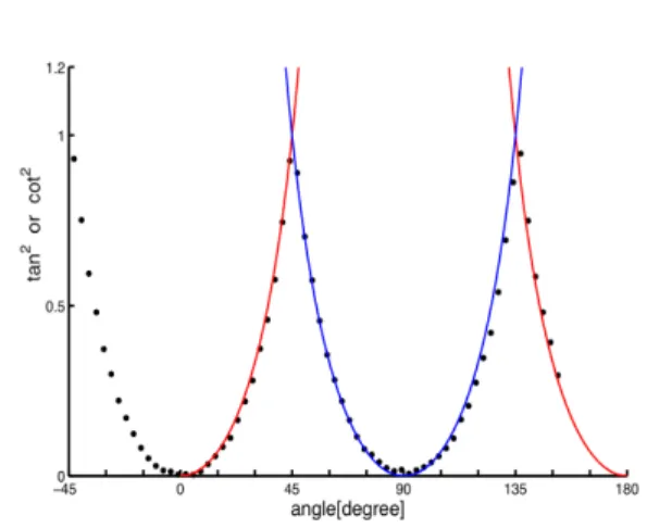
Fig. 11 Regression of ratio of two amplitudes with square of the trigonometric functions
Fig. 12 Schematic diagram of obtaining specimen for propagation direction of [210]
incident waves. At each case, ratio of amplitude of [001] and [110] wave was calculated and plotted. When the ratio between two amplitudes was bigger than 1, the inverse of the ratio was plotted. Fig. 11 is the regression of the plot with cot and tan.
The plotted experimental values have period of π [rad], and the maximum value of ratio is 1 at the same positions where the squares of cotangent and tangent intersect. As one amplitude increased, the other decreased, and each com- ponent had its maximum when the incident bulk transverse wave was parallel to its oscillation direction. The two amplitudes becomes the same when the incident transverse wave is 45˚ from [001] axes, and 45˚ from [110] axes.
5. Ultrasound Propagation in [210] Direction 5.1. Silicon Crystal Specimen
The [210] specimen is obtained from the [100] specimen of 20 mm thickness and 50 mm diameter as shown in Fig. 12. Cutting direction was determined by considering the skew angle as well as the crystal orientation [12]. The oscillation direction of quasi-transverse wave is parallel to the surface contacting with transducer, and the direction of propagation is in [210]
direction. Therefore the specimen is cut along the line which makes an angle of 7.13˚ with the line normal to the [210] direction. Thickness of
obtained specimen, distance between line 1 and 2, was 1.55 cm.
5.2. Direction of the Quasi-Transverse Wave Reflection Point of the Quasi-Transverse Wave in [210] Direction
The solution of Christoffel’s equation for [210] direction is summarized in Table 4. Since angle between the oscillation direction and the propagating direction of the quasi-transverse wave is 97.13°, the propagating direction of the quasi-transverse wave was predicted to be deviated by 7.13° from the normal to the surface of medium.
Two transverse wave probes of 10 MHz (Ultran SWC25-10, 6 mm element size) were used in this experiment. Signals were detected
Fig. 14 Signals of the transverse wave (left) and the quasi-transverse wave (right)
Table 4 Solution of Christoffel’s equation for [210]
direction
Wave Oscillating
direction Speed
Transverse [001] 5842.9 m/s
Quasi-transverse [1,-1.55,0] 5060.6 m/s Quasi-longitudinal [1.55,1,0] 8924.7 m/s
Fig. 13 Amplitude according to the angle from the transmitter probe
by pitch-catch method. The transmission probe was attached to the center of one side and the receiver probes moved along the other side.
Since the wave spreads out from the propagation direction as the center, maximum signal amplitude is recorded at the propagation direction. The signal amplitude of the quasi- transverse wave was measured using the receiver probe that traveled along the other side in the interval of 2 mm in order to determine the arrival point of the quasi-transverse wave, and result is shown in Fig. 13. The maximum peak of the signal appeared around 9.76°. This value is different by 2.63° from the predicted one.
5.3. Birefringence in [210] Direction
In this research, we focused on the propa- gation of two transverese waves. The incident transverse wave, propagating in [210] direction and oscillating in arbitrary direction, was generated by 10 MHz shear wave probe. Then, their time durations and amplitudes were measured by the same probe using pulse/echo method. Since
speeds of the quasi-transverse wave and the transverse wave were 5060 m/s and 5843 m/s respectively, those waves were expected to be detected around 6.2 μs and 5.3 μs. The trans- mission probe rotated total of 90° in 10° step.
Fig. 14 shows typical pulse-echo signal obtained from the specimen. The quasi-transverse wave and the transverse wave are indicated with arrows in Fig. 14. Time of flights of the quasi-transverse wave and the transverse wave were 6.1 μs and 5.2 μs, respectively. They were both different by 0.1 μs from predicted values.
In order to analyze the amplitude decom- position in [210] direction, the ratio of two peaks shown in Fig. 14 was measured as similar to [110] direction. The results was similar to that in [110] direction as shown in Fig. 11, since oscillation directions of them are perpen- dicular to each other.
6. Conclusion
Speeds and oscillation directions of elastic waves propagating in [ab0] direction of silicon single crystal were obtained by solving Christoffel’s equation. One longitudinal wave and two transverse waves can propagate with different wave speeds. It was found that quasi waves propagate in off-principal axis, so that directions of phase and group velocities are not the same. Maximum deviation of two directions
[210] direction was similar to that in [110]
direction, since oscillation directions of them are perpendicular to each other.
These results offer useful information in measuring the crystal orientation of single crystal silicon. In general, the determination of [001] silicon orientation was determined using complex methods [13,14]. However, this result gives may be applied to determine the axes of single crystals such as silicon.
Acknowledgments
This work was supported by the Korea Science Academy of KAIST with funds from the Ministry of Science, ICT and Future Planning.
References
[1] Joseph L. Rose, "Ultrasonic Waves in Solid Media," Cambridge University Press, New York, pp. 225-226 (2004)
[2] N. N. Hsu, "Acoustical birefringence and the use of ultrasonic waves for experimental stress analysis," Experimental Mechanics, Vol. 14, pp. 169-176 (1973)
[3] A. Arora, "Effect of texture and stress on acoustic birefringence," Scripta Metallurgica, Vol. 18, pp. 763-766 (1984)
[4] K. Goebbels and S. Hirsekorn, "A new ultrasonic method for stress determination in textured materials," NDT International,
izations," Optics and Lasers in Engineering, Vol. 22, pp. 305-323 (1995)
[8] H. -J. Jeong, and L. W. Schmerr, Jr.
"Effects of material anisotropy on ultrasonic beam propagation: diffraction and beam skew," Journal of the Korean Society for Nondestructive Testing, Vol. 26, No. 3, pp. 198-205 (2006)
[9] H. -J. Jeong and L. W. Schmerr, Jr.
"Ultrasonic beam propagation in highly anisotropic materials simulated by multi- gaussian beams," Journal of Mechanical Science and Technology, Vol. 21, No. 8, pp. 1184-1190 (2007)
[10] H. F. Pollard, "Sound Waves in Solids,"
Pion, London, pp. 11-20, (1977)
[11] M. A. Hopcroft, W. D. Nix and T. W.
Kenny, "What is the Young’s modulus of silicon?," Journal of Microelectromechanical Systems, Vol. 19, pp. 229-238 (2010) [12] N. Maluf and K. Williams, "An Intro-
duction to Microelectromechanical Systems Engineering, 2nd Ed." Artech House, Boston, pp. 13-17 (2004)
[13] G. Ensell, "Alignment of mask patterns to crystal orientation," Sensors Actuators A, Vol. 53, pp. 345–348 (1996)
[14] F. Tseng and K. Chang, "Precise [100]
crystal orientation determination on 110- oriented silicon wafers," Journal of Micromechanics and Microengineering., Vol. 13, No. 1, pp. 47-52 (2003)
![Fig. 3 Skewing angle in [ab0] direction](https://thumb-ap.123doks.com/thumbv2/123dokinfo/4744249.514348/3.808.102.372.410.639/fig-skewing-angle-in-ab-direction.webp)
![Fig. 5 15º with respect to [001] direction Fig. 8 60º with respect to [001] direction](https://thumb-ap.123doks.com/thumbv2/123dokinfo/4744249.514348/5.808.91.719.75.938/fig-º-respect-direction-fig-º-respect-direction.webp)
![Table 4 Solution of Christoffel’s equation for [210]](https://thumb-ap.123doks.com/thumbv2/123dokinfo/4744249.514348/7.808.91.386.148.452/table-solution-christoffel-s-equation.webp)
